US1853904A - Refrigerating apparatus - Google Patents
Refrigerating apparatus Download PDFInfo
- Publication number
- US1853904A US1853904A US467808A US46780830A US1853904A US 1853904 A US1853904 A US 1853904A US 467808 A US467808 A US 467808A US 46780830 A US46780830 A US 46780830A US 1853904 A US1853904 A US 1853904A
- Authority
- US
- United States
- Prior art keywords
- dome
- evaporator
- vertical
- pipes
- loops
- Prior art date
- Legal status (The legal status is an assumption and is not a legal conclusion. Google has not performed a legal analysis and makes no representation as to the accuracy of the status listed.)
- Expired - Lifetime
Links
- 239000002184 metal Substances 0.000 description 7
- 230000008014 freezing Effects 0.000 description 5
- 238000007710 freezing Methods 0.000 description 5
- 239000007788 liquid Substances 0.000 description 3
- 239000003507 refrigerant Substances 0.000 description 2
- 239000011324 bead Substances 0.000 description 1
- 238000009434 installation Methods 0.000 description 1
- 238000004519 manufacturing process Methods 0.000 description 1
- 238000007789 sealing Methods 0.000 description 1
- 229910000679 solder Inorganic materials 0.000 description 1
Images
Classifications
-
- F—MECHANICAL ENGINEERING; LIGHTING; HEATING; WEAPONS; BLASTING
- F25—REFRIGERATION OR COOLING; COMBINED HEATING AND REFRIGERATION SYSTEMS; HEAT PUMP SYSTEMS; MANUFACTURE OR STORAGE OF ICE; LIQUEFACTION SOLIDIFICATION OF GASES
- F25B—REFRIGERATION MACHINES, PLANTS OR SYSTEMS; COMBINED HEATING AND REFRIGERATION SYSTEMS; HEAT PUMP SYSTEMS
- F25B39/00—Evaporators; Condensers
- F25B39/02—Evaporators
Definitions
- This invention relates to refrigerating apparatus and more particularly to evaporators.
- the evaporator In refrigerating installations such as are used for household purposes the evaporator must withstand pressures of the order of 200 pounds to the square inch, while at the same time be cheap to manufacture. Because of these requirements it is desirable that the evaporator consist of as few elements asposwv .15
- An object of this invention is to devise an evaporator which may be made of a plurality p of pipes and sheet metal stampings, and comprising a minimum of such elements.
- A- further object is to devise an evaporator in which 20 thin sheet metal may be used and which, because of its circular configuration, will withstand the pressure. l
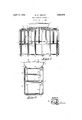
- v Figure 1 a side view of the evaporator
- Figure 2 is a sectional front view.
- the evaporator comprises a dome 1,in which is adapted to'be maintained a predetermined p refrigerant.
- -Dom'e 1 conopen dish-shaped 'pan 2, whose side 'slopesmwardly at 3, and-an outwardly dished bottom 4.
- Member 2 may be made of a single piece of sheet metal stamped and drawn to the desired size and shape. The top of thezdome is sealed by a dished cover plate 6, whose periphery is disposed within the folded over edge 7 of member 2.
- each pipe comprises a generally horizontal top portion 10 extending from the gas dome outwardly to'verticalplanes disposed at equal distances on opposite sides of the gas quantity of liquid "dome. The pipes are then bent downwardly to form vertical portions 11 and 15.
- Every other pipe has vertical portion 15 which extends only part way down the evap: orator and is then cross-connected by a horizontal portion 16.
- Vertical portions 11 and 15 on each side of dome 1 are preferably in longitudinal alignment with each other.
- Horizontal portions 12 and 16 are also aligned.
- Supportedwithin the two series of loops are metal sleeves and 26 in intimate thermal contact with the vertical sides of the pipes.
- Sleeve 26 is divided by a shelf 27 and has ice trays 28 and 29 disposed therein.
- a bottom tray 29 in sleeve 25 may be used for the storage of food if desired.
- Cover 6 may be assembled easily and may have the pipes soldered to the head from the inside. Obviously, when cover 6 is in place the junctions of the pipe and the gas dome will be easily accessiblee Cover 6 may be sealed in lace by the simple expedient of, running molten solder around bead 7 and sealing the head tightly. Inlet and outlet pipesfor liquid and gasified refrigerant may be disposed at 32 and 33 or any other place. Suitable mechanism for controlling the liquid level in dome, 1 may be incorporated if desired.
- An evaporator comprising a dome of two sheet metal members,--said members consistin of an open circular pan and cover there or, a plurality of duct loops depending from said dome, said loops extending radlally in a. enerally horizontal direction from said dome,'then extending vertically forming two series of aligned pipes and havmg horizontal portions joining said vertical portions v 2;
- An evaporator comprising a dome of.
- said members consistin of an open circular pan and cover there or, a plurality of duct loops depending from-said dome,'each-.1oop being connected to the dome at points symmetrically disposed with respect to the longitudinal axis of the evaporator, said ducts extending radially from said dome in a generally horizontal d1- rection then downward to form vertical portions, the vertical portions of said ducts lying in vertical planes on each side of the dome, certain of said vertical Eortions extending a eater distance down t an others, and horizontal portions joining the various vertical portions to define a plurality of freezing compartments within said loops.
- An evaporator comprising a dome of two sheet metal members, said members ingan open circular pan and cover therefor,
- duct loops depending from said dome and being so shaped as toform 'a freezing area within the loops, of a substantially rectan lar cross section, all of said ducts exten mg radially from said dome in a generally horizontal direction, and having aligned vertical ortions, the bottoms of which are joined y horizontal portions, alternate ducts extending downwardly to the 25 bottom of the freezing area, while remaining ducts only extend a portion of the way down the freezing area.
Description
April 12, 1932. M. w. KENNEY REFRTGERATING APPARATUS Filed July 14, 1950 INVENTOR MM/(E/v ATTO NEY 80 sists of a circular,
Patented A r. 12, 1932 UNITED. STATES PA NT O KAHLON w. KENNEY, oF'ELmHUBs'r, ILLINOIS, AssIGNoR, BY MEsnE ASSIGNMENTS.
' ro GBIGSBY-GBUNOW COMPANY, A coRroRA'rIoN or ILLINOIS mnreanarme arrmrus Application filed July 14,
' This invention relates to refrigerating apparatus and more particularly to evaporators. In refrigerating installations such as are used for household purposes the evaporator must withstand pressures of the order of 200 pounds to the square inch, while at the same time be cheap to manufacture. Because of these requirements it is desirable that the evaporator consist of as few elements asposwv .15 An object of this invention is to devise an evaporator which may be made of a plurality p of pipes and sheet metal stampings, and comprising a minimum of such elements. A- further object is to devise an evaporator in which 20 thin sheet metal may be used and which, because of its circular configuration, will withstand the pressure. l
' Referringtothe drawings:
v Figure 1 a side view of the evaporator;
. and
Figure 2 is a sectional front view. I
The evaporator comprises a dome 1,in which is adapted to'be maintained a predetermined p refrigerant. -Dom'e 1 conopen dish-shaped 'pan 2, whose side 'slopesmwardly at 3, and-an outwardly dished bottom 4. Member 2 may be made of a single piece of sheet metal stamped and drawn to the desired size and shape. The top of thezdome is sealed bya dished cover plate 6, whose periphery is disposed within the folded over edge 7 of member 2. 1 1
Radially disposed from portion. 3 of the dome are a p lurality of'pi'pes orducts. The corresponding ends of every pipe are connected at pointsalong portion 3 symmetrically disposed withrespect to a vertical bisectin'g plane. Each pipe comprises a generally horizontal top portion 10 extending from the gas dome outwardly to'verticalplanes disposed at equal distances on opposite sides of the gas quantity of liquid "dome. The pipes are then bent downwardly to form vertical portions 11 and 15. The
' '50 vertical portions 11 of certain pipes are con- 1930.. Serial No. 467,808.
nected by horizontal portions 12 and form loops defining a freezing area within.
Every other pipe has vertical portion 15 which extends only part way down the evap: orator and is then cross-connected by a horizontal portion 16. Vertical portions 11 and 15 on each side of dome 1 are preferably in longitudinal alignment with each other. Horizontal portions 12 and 16 are also aligned. Supportedwithin the two series of loops are metal sleeves and 26 in intimate thermal contact with the vertical sides of the pipes. Sleeve 26 is divided by a shelf 27 and has ice trays 28 and 29 disposed therein. A bottom tray 29 in sleeve 25 may be used for the storage of food if desired. I
Obviously, the relative positions and numbers of vertical portions 11 and 15 may be varied as desired. .In fact, all the pipes may be extended down the full depth of the evaporator if desired.
' type may be assembled easily and may have the pipes soldered to the head from the inside. Obviously, when cover 6 is in place the junctions of the pipe and the gas dome will be easily accessiblee Cover 6 may be sealed in lace by the simple expedient of, running molten solder around bead 7 and sealing the head tightly. Inlet and outlet pipesfor liquid and gasified refrigerant may be disposed at 32 and 33 or any other place. Suitable mechanism for controlling the liquid level in dome, 1 may be incorporated if desired.
I claim: 3 1. An evaporator comprising a dome of two sheet metal members,--said members consistin of an open circular pan and cover there or, a plurality of duct loops depending from said dome, said loops extending radlally in a. enerally horizontal direction from said dome,'then extending vertically forming two series of aligned pipes and havmg horizontal portions joining said vertical portions v 2; An evaporator comprising a dome of. two sheet metal members, said members consistin of an open circular pan and cover there or, a plurality of duct loops depending from-said dome,'each-.1oop being connected to the dome at points symmetrically disposed with respect to the longitudinal axis of the evaporator, said ducts extending radially from said dome in a generally horizontal d1- rection then downward to form vertical portions, the vertical portions of said ducts lying in vertical planes on each side of the dome, certain of said vertical Eortions extending a eater distance down t an others, and horizontal portions joining the various vertical portions to define a plurality of freezing compartments within said loops.
y 3'. An evaporator comprising a dome of two sheet metal members, said members ingan open circular pan and cover therefor,
a plurality of duct loops depending from said dome and being so shaped as toform 'a freezing area within the loops, of a substantially rectan lar cross section, all of said ducts exten mg radially from said dome in a generally horizontal direction, and having aligned vertical ortions, the bottoms of which are joined y horizontal portions, alternate ducts extending downwardly to the 25 bottom of the freezing area, while remaining ducts only extend a portion of the way down the freezing area. f tmh testimony whereof he aflixes his signa- 3 MAHLON W. KENNEY.
Priority Applications (1)
| Application Number | Priority Date | Filing Date | Title |
|---|---|---|---|
| US467808A US1853904A (en) | 1930-07-14 | 1930-07-14 | Refrigerating apparatus |
Applications Claiming Priority (1)
| Application Number | Priority Date | Filing Date | Title |
|---|---|---|---|
| US467808A US1853904A (en) | 1930-07-14 | 1930-07-14 | Refrigerating apparatus |
Publications (1)
| Publication Number | Publication Date |
|---|---|
| US1853904A true US1853904A (en) | 1932-04-12 |
Family
ID=23857266
Family Applications (1)
| Application Number | Title | Priority Date | Filing Date |
|---|---|---|---|
| US467808A Expired - Lifetime US1853904A (en) | 1930-07-14 | 1930-07-14 | Refrigerating apparatus |
Country Status (1)
| Country | Link |
|---|---|
| US (1) | US1853904A (en) |
-
1930
- 1930-07-14 US US467808A patent/US1853904A/en not_active Expired - Lifetime
Similar Documents
| Publication | Publication Date | Title |
|---|---|---|
| US1853904A (en) | Refrigerating apparatus | |
| US1952148A (en) | Refrigerating apparatus | |
| US2104845A (en) | Refrigerator | |
| US1897997A (en) | Absorber for refrigerating systems | |
| US2332349A (en) | Refrigerating unit | |
| US2546737A (en) | Sheet metal evaporator | |
| US1906296A (en) | Evaporator | |
| US1887933A (en) | Refrigerating apparatus | |
| US1845640A (en) | Cooler | |
| US2143169A (en) | Refrigeration apparatus | |
| US2135402A (en) | Refrigerator | |
| US2414952A (en) | Evaporator unit | |
| US1929938A (en) | Evaporator and shelf | |
| US1888331A (en) | Refrigerating apparatus | |
| US1728827A (en) | Refrigerating apparatus | |
| US2323186A (en) | Refrigeration | |
| US2551465A (en) | Refrigerant evaporator | |
| US2057408A (en) | Cooling element for refrigerating systems | |
| US2466541A (en) | Gas and liquid contact apparatus | |
| USRE21830E (en) | Refrigerating apparatus | |
| US1854468A (en) | Refrigerating cabinet | |
| US1992379A (en) | Refrigeration apparatus | |
| US1973127A (en) | Cooling element for refrigerating systems | |
| US1829407A (en) | Refrigerating apparatus | |
| US2114204A (en) | Brine tank |