US1853880A - Capped pin - Google Patents
Capped pin Download PDFInfo
- Publication number
- US1853880A US1853880A US426457A US42645730A US1853880A US 1853880 A US1853880 A US 1853880A US 426457 A US426457 A US 426457A US 42645730 A US42645730 A US 42645730A US 1853880 A US1853880 A US 1853880A
- Authority
- US
- United States
- Prior art keywords
- pin
- cap
- prong
- flange
- head
- Prior art date
- Legal status (The legal status is an assumption and is not a legal conclusion. Google has not performed a legal analysis and makes no representation as to the accuracy of the status listed.)
- Expired - Lifetime
Links
Images
Classifications
-
- A—HUMAN NECESSITIES
- A47—FURNITURE; DOMESTIC ARTICLES OR APPLIANCES; COFFEE MILLS; SPICE MILLS; SUCTION CLEANERS IN GENERAL
- A47C—CHAIRS; SOFAS; BEDS
- A47C31/00—Details or accessories for chairs, beds, or the like, not provided for in other groups of this subclass, e.g. upholstery fasteners, mattress protectors, stretching devices for mattress nets
- A47C31/02—Upholstery attaching means
- A47C31/026—Upholstery attaching means passing through the upholstery, e.g. upholstery nails or buttons
-
- Y—GENERAL TAGGING OF NEW TECHNOLOGICAL DEVELOPMENTS; GENERAL TAGGING OF CROSS-SECTIONAL TECHNOLOGIES SPANNING OVER SEVERAL SECTIONS OF THE IPC; TECHNICAL SUBJECTS COVERED BY FORMER USPC CROSS-REFERENCE ART COLLECTIONS [XRACs] AND DIGESTS
- Y10—TECHNICAL SUBJECTS COVERED BY FORMER USPC
- Y10T—TECHNICAL SUBJECTS COVERED BY FORMER US CLASSIFICATION
- Y10T24/00—Buckles, buttons, clasps, etc.
- Y10T24/46—Pin or separate essential cooperating device therefor
- Y10T24/468—Pin or separate essential cooperating device therefor having interconnected distinct penetrating portions
- Y10T24/4688—Pin or separate essential cooperating device therefor having interconnected distinct penetrating portions formed from common wire
Definitions
- My the wire,and'-to.formimain pin 11 at one invention contemplates theprovision of apin end .o'f'the "length of vwire and a secondary "fastener ha ving simple and eflicient means pin or prongfilfz at the other end of the forpreventi'ngwithdrawal of the pin after lengthof Wire. i 1 it has-once heen inserted into place.
- Said-head '10 is preferably continuous and which issoconstructedthat the cap assumes unbroken throughout its entire length and is a fiat' position and lies flat-on the fabric after adapted to have a suitable ca'p as 13 secured it liasbeeninserted into place. 7 thereto, and whileishown asrarcuate or part- 7-0
- FigQ isaside view' of; he pin with the cap
- the cap '13' is preferably'made of sheet ma V assembled in place thereon, part of the'cap 'terial such-assheet' metal, celluloid, horn,or 39 being broken away to show the *arcuate'head other sheet material'suitable' and "heretofore of the pin, and the cap flange applied thereto.
- customarily used in the making of buttons v Fig. 3 isa rear view of the pin, showing "caps'tor buttons, fasteners, or thellike'.
- the rmain pin and the ⁇ prong Theca'p lB is preferably providedwifth'a passed through said certain slots "between peripherah rearwardly'arranged flange as 14 adjacentfingersto prevent turning-movement adapted to be bent forwardly and outwardly prong-relatively to eadhother and to the cap. pin.
- the cap In orderito provideja' fiange'l letwhic'h of the pin relativelyto the cap.
- Fig. 4 is'a rear view of my improvedpin as ly and permanently. While the flange in it appears whenin operative position applied Figs.
- Figs. -6 to 17 inclusive are rear views of Said blank ismade of the proper shapeto be 1 various forms of my invention, showing a bent into its final circular :t'orm, or it may be ifiewof the manytyp-ica'l arrangements of the made polygonal in" outline so as to be bent mainypin and of the withdrawal preventing into polygonal form about the-head 0f the may be readily bent about the head 10 of the wire with maximum efliciency and ease, and to present an increased, smooth appearance,
- the slots 18 are further more comparatively closely spaced so that either the prong 12 or the main pin 11 at the points 20 and 21, respectively, may pass through one of the slots 18, and between adjacent pairs of fingers 19.
- the wire member is. not only firmly secured to the cap 13 but is prevented from rotating relatively to the cap. Since the slotsare comparatively closely spaced, at least one of the pins will pass through a slot even though the cap and the wire member are assembled more or less inaccurately and without deliberately arranging one or both of the pins in the slots.
- the main pin 11 is bent from one end as'30 of the head 10 so that at the point 15, where the pin 11 passesthe flange 14, said pin is in pressed or sprung contact with said flange. If the bend 30 does not extend rearwardly to any substantial extent, the pin 11 may therefore assume a slightly rearward direction to pass the opposite point 15 of the flange. As the pin 11 is passed through and under the fabric, the fabric sheet is forced between the pin 11 and the flange 14 at the point 15 to separate the pin from the flange at that point, and the fabric is thereby frictionally gripped between the pin and the flange.
- the secondary pin or prong 12 is bent from the other end 31 of the head 10, and is arranged to extend in a direction approximately opposite to that of the pin 11, said pin 12 being entirely inside-of the cap, and present ing a rearwardly directed point.
- the prong 12 may be arranged so as to contact with the main pin 11, being sprung toward said main pin, so that the fabric entering between the prong and the pin is frictionally gripped therebetween as at 32, owing to their tendency to come together.
- the tendency to'compress, tension or otherwise stress the fabric between the pin and the prong may be otherwise induced, as for example, by directing the prong at various angles to the pin as shown in Figs. 6, 7, 8, 9 and 12 to 17 inclusive.
- the cooperating action above described, I have found, tends to assist the prong 12 in preventing withdrawal of the pin from the fabric, or "accidental loosening of the pin.
- the fabric stressing cooperating of the pin and prong may also be attained, if desired,as illustrated, without sprung contact of the pin and prong.
- the main pin 11 is passed through the slip cover 22 which is to be secured in place, and through the permanently arranged upholstery fabric 23, until the pin point 24 contacts with the wood or metal panel or other rigid backing 25.
- the resistance of said backing 25 causes the pin point to slide along the surface 26 of said back and to lie between said surface and the upholstery 23,
- the retracting movement in the direction of the main pin causes the prong 12 to pull or push the fabric away from or toward the main pin to stress the fabric, depending upon the direction in which the prong extends.
- the prong crosses or contacts with the main pin, the prong is forced by the fabric entering therebetween away from the main pin and due to its normal sprung engagement with the main pin, causes the fabric to be frictionally gripped there-.
- the prong 12 is in such sprung contact with the main pin 11 and thereby aids in preventing withdrawal of the pin.
- the point 27 of h the prong 12 may extend rearwardly of the main pin 11, and that said prong is preferably directed rearwardly to a sufficient extent to accomplish that purpose. It will be understood, however, thatthe prong need not necessarily be of such length and may terminate forwardly of the pin 11 or in the same plane as said pin, if desired, without materially affecting the proper operation thereof. 7
- said prong -.be id ispos ed eat any angleato bring it within the :cap, ;as :may :be
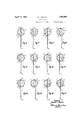
- I ig. 1 5 shows a similarl-structure excepting that thehead of the wire isthere made to subtend :an angle greater thanzi180 and less than 27 0, whereas in Fig.7, the head subten'ds an angle of less than 180.
- A. pin fastener comprising a single length of wire pointed at both ends thereof and including alonger'pin element bent from one end of the wire to extend intone direction, and a shorter Pinelementbent from.
- a pin fastener comprising a cap terminating in a peripheral rear flange, and a length of round wire held by said cap between the iiange and the rear'faceofthe re- .ma'inder of the cap, said length of wire harving an-arcuate portion bent from the wire intermediate the ends thereof, nearer oneend of said length-of were than-the other, a pointed prong integral with the lower end of said arcuate' portion "and bent in a direction to extend rearwardly and upwardlytherefrom, and a substantially straight "mainipin bent from the other endofsa'id'arcuate po -r tion and extending downwardly therefrom past the lowermost part of said fiangeand pointed at its'lowermost extremity.
- main pin bent from v. the" upper end of the head and extending downwardly past, .and in pressed contact with, the lower ,part of'the flange, and a prong bent from the other end of the head of less length than themain pin, and directed rearwardly and approximately upwardly and also directed transversely to-Warda side of the cap int-oangular relation to the main pin, and so positioned relatively to the main pin as to stress that ,portion offithe fabric sheets 'lying between I said prong and said ,main pin into which the fastener is inserted afterlsaid' main pin has been .passed into the ⁇ fabric as ,far ⁇ as possible ;-in one direction and then retracted.
- ilength of :wire ipointed at both ends a d :se- :cured tosaid cap by said Zflange said -ilength of wire including a head intermediate the ends thereof and inserted in front of said flange and held thereby, a main pin bent from one end of said head extending in one direction, normally in contact with the flange and adapted to pass into a piece of fabric for compressing the fabric between the main pin and the adjacent part of the flange, and a prong bent from the other end of the head to extend toward a side of the cap and rearwardly and upwardly and terminating in a free point and having its fixed end spaced from the bent end of the main pin section approximately 180 and extending approximately in the opposite direction to enter the fabric onthe partial retraction of the fastener therefrom and to prevent total retraction of the main pin from the fabric.
- a pin fastener comprising a cap of sheet material having a rear flange and a length of wire pointed at both ends secured to the cap by said flange, said length of wire including a continuous arcuate head intermediate of its ends and inserted forwardly of and engaging said flange throughout its length and held thereby to the cap, a substantially straight main pin extending in one direction from the upper end of said head and a prong extending in substantially the opposite direction.
- said prong being arranged to extend angularly relatively to the main pin and toward one side of the cap to exert stress upon that portion of the material in which said fastener is operatively inserted and included between the points of engagement of said pin and prong with said materials.
- a pin fastener comprising an imperforate cap of sheet material having its front portion convexed forwardly and terminating in a peripherally slotted rear flange and a length of wire pointed at both ends secured to the cap by said flange, said length of wire including a continuous arcuate head intermediate of its ends and inserted forwardly of said flange and held thereby to the cap, a substantially straight main pin extending in one direction from the upper end of said head and passing through one of the peripheral slots of the flange, and a prong extending in substantially the opposite direction from the extreme end of said head and integral there with, to a point rearwardly of the main pin, and passing through another of said slots spaced angularly from the first-mentioned slot approximately 180.
- a pin fastener comprising a cap terminating in a peripheral flange and a length of wire held intermediate its endsby said flange to the cap, said length of wire including an intermediate head shaped throughout its entire length to conform to the shape of the flange and held thereby throughout its entire length, a pointed main pin bent from one end of the head, crossing the rear of said cap and extending past said cap, and a shorter secondary pointed pin bent from the other end of the length of wire and extending generally rearwardly and toward the juncture of the main pin and the head, said secondary pin extending toward a side of the cap and angularly arranged relatively to the main pin to stress the material through which the main pin is passed after partial retraction of said main pin.
- a pin fastener the combination with a sheet metal head having a front portion and a rear terminal flange provided with peripheral spaced slots forming peripheral fingers therebetween, of a length of round wire having a head intermediate of its ends, said head being held to said cap throughout its entire length by bending said fingers forwardly about said head, a straight main pin bent from the upper end of said head and sprung into contact with said flange at a point near the lowermost part of said flange, said main pin being pointed at its lowermost end, and a pointed prong bent from the other end of said head upwardly and rearwardly and in pressed contact with said main pin at a point intermediate of the ends of the prong, the point of said prong being arranged rearwardly of said main pin and above the center of the cap, whereby said prong stresses the material through which the main pin is passed after partial retraction of said main pin and said main pin compresses the material between it and said flange and withdrawal of the pin from the material is thereby resisted.
Description
April 12, 1932.
REITER GAPPED PIN 2 SheetsSheet 1 Filed Feb. '7. 1930 \\VENTOR Dame] 1. Feller ATTORNEY April 12, 1932. RE|TER I 1,853,880
CAPPED. PIN
Filed Feb. '7, 19,30 2 Sheets-Sheet 2 Daniel I Pez'zer BY I zRNEY I Patented Apr. 12, 1932 a 1 l i I iris PAT E DANIEL I. REITER, oninnw YORK. it; Y
joiurnnrm V Application lfiletl "February 7, 1930. Serial imeaa ita This invention relates to cappedpin fas- In that practical embodiment of my inteners and particularly, to those designed to vention whichl have illustrated by wayjof pin togetherthe ii'abric slip covers ofqautoexample, I provide-a single length of wire mobiles and the fabric upholstery thereof which 'is pointed atb'oth of'it s ends andfbent 5 without the *aid of snap fasteners, and deinto proper'shape toform ahead orcapefi- 5 signed 'further to resist "withdrawal of the gaging portion llOintermediate of the ends of fastener accidentally or intentionally. My the wire,and'-to.formimain pin 11 at one invention contemplates theprovision of apin end .o'f'the "length of vwire and a secondary "fastener ha ving simple and eflicient means pin or prongfilfz at the other end of the forpreventi'ngwithdrawal of the pin after lengthof Wire. i 1 it has-once heen inserted into place. I The head :10, intermediateofthe ins 11 My invention further contemplates-the pro- Y and 12, is preferably made arcuate in shape 7 :visionof apin'fastener which is'designed for to conform ito the shape of theperipheral economical manufacture "in large quantities partiof thecap 13, and preferablysubtends an and which is simple 'in construction, easy to angle of less than 270 or of approximately insert rapidly by unskilled persons, eficient 1'80=in all of the modified'iforms illustrated.
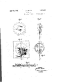
in operation and'ine'xpensive to produce,and Said-head '10 is preferably continuous and which issoconstructedthat the cap assumes unbroken throughout its entire length and is a fiat' position and lies flat-on the fabric after adapted to have a suitable ca'p as 13 secured it liasbeeninserted into place. 7 thereto, and whileishown asrarcuate or part- 7-0 The various objects of =m'y invention will ly circular in shape, maybeunade ofzany debe clear *from't'he description which follows, sired shape such as polygonal, :square and and fromthedrawings, in which, the like to conform to thesh'ape of the cap Fig. 1 is an elevational view of the blank used-therewith, without departing from the from which the capof my improved pin may spirit of "the invention, and as will be obvibe *formed, showing particularly, the "termious to those skilledi-n'the art, andhence which nal fingersand slots thereof. V 'need not be shownorfifurtherdescribed.
FigQ isaside view' of; he pin with the cap The cap '13'is preferably'made of sheet ma V assembled in place thereon, part of the'cap 'terial such-assheet' metal, celluloid, horn,or 39 being broken away to show the *arcuate'head other sheet material'suitable' and "heretofore of the pin, and the cap flange applied thereto. customarily used in the making of buttons, v Fig. 3 isa rear view of the pin, showing "caps'tor buttons, fasteners, or thellike'. particularly, the rmain pin and the {prong Theca'p lB is preferably providedwifth'a passed through said certain slots "between peripherah rearwardly'arranged flange as 14 adjacentfingersto prevent turning-movement adapted to be bent forwardly and outwardly prong-relatively to eadhother and to the cap. pin. In orderito provideja' fiange'l letwhic'h of the pin relativelyto the cap. V to a suflici'ent extent togripthe headlOfirm- "Fig. 4 is'a rear view of my improvedpin as ly and permanently. While the flange in it appears whenin operative position applied Figs. 6 to 17 inclusiveisshown 'as continuous, to two layers offabric, showing the cooperaunserrated and unslitted, torpurposesiofrease t ion between'the prong and the main pin se'cof illustration :and clarity, it will be under- 'tion to stress the fabric. i stoodthat' the terminal edges of said flange F'gjis-across-sect'onal View of *p'art-of-the may be serrated or'slitted or 'both,' if desired, upholstered body ofan automobile showing in the manner shown injFigs. 1, Q-Iand 3. the pin in operative position for securing the Referring to Fig; l, I have there shown "a Slipcover to the upholstery, and blank from which the cap 13 maybe formed.
Figs. -6 to 17 inclusive are rear views of Said blank ismade of the proper shapeto be 1 various forms of my invention, showing a bent into its final circular :t'orm, or it may be ifiewof the manytyp-ica'l arrangements of the made polygonal in" outline so as to be bent mainypin and of the withdrawal preventing into polygonal form about the-head 0f the may be readily bent about the head 10 of the wire with maximum efliciency and ease, and to present an increased, smooth appearance,
' I prefer to provide a series of spaced slots as 18 cut inwardly from the peripheral edge of the blank and forming a series of spaced fingers 19 therebetween. Said. fingers may be readily bent about the head 10 by means of a simple clinching tool to hold the wire properly in place. The slots 18 are further more comparatively closely spaced so that either the prong 12 or the main pin 11 at the points 20 and 21, respectively, may pass through one of the slots 18, and between adjacent pairs of fingers 19. By so arranging the pin and prong to extend through slots between adjacent pairs of fingers, the wire member is. not only firmly secured to the cap 13 but is prevented from rotating relatively to the cap. Since the slotsare comparatively closely spaced, at least one of the pins will pass through a slot even though the cap and the wire member are assembled more or less inaccurately and without deliberately arranging one or both of the pins in the slots.
The main pin 11 is bent from one end as'30 of the head 10 so that at the point 15, where the pin 11 passesthe flange 14, said pin is in pressed or sprung contact with said flange. If the bend 30 does not extend rearwardly to any substantial extent, the pin 11 may therefore assume a slightly rearward direction to pass the opposite point 15 of the flange. As the pin 11 is passed through and under the fabric, the fabric sheet is forced between the pin 11 and the flange 14 at the point 15 to separate the pin from the flange at that point, and the fabric is thereby frictionally gripped between the pin and the flange. Similarly, the secondary pin or prong 12 is bent from the other end 31 of the head 10, and is arranged to extend in a direction approximately opposite to that of the pin 11, said pin 12 being entirely inside-of the cap, and present ing a rearwardly directed point. As shown in Figs. 3, 6, 16 and 17, the prong 12 may be arranged so as to contact with the main pin 11, being sprung toward said main pin, so that the fabric entering between the prong and the pin is frictionally gripped therebetween as at 32, owing to their tendency to come together.
The tendency to'compress, tension or otherwise stress the fabric between the pin and the prong may be otherwise induced, as for example, by directing the prong at various angles to the pin as shown in Figs. 6, 7, 8, 9 and 12 to 17 inclusive. The cooperating action above described, I have found, tends to assist the prong 12 in preventing withdrawal of the pin from the fabric, or "accidental loosening of the pin. The fabric stressing cooperating of the pin and prong may also be attained, if desired,as illustrated, without sprung contact of the pin and prong.
To insert the pin fastener in place, the main pin 11 is passed through the slip cover 22 which is to be secured in place, and through the permanently arranged upholstery fabric 23, until the pin point 24 contacts with the wood or metal panel or other rigid backing 25. The resistance of said backing 25 causes the pin point to slide along the surface 26 of said back and to lie between said surface and the upholstery 23,
though the pin point may, to a slight extent,
rise again to enter the upholstery 23. When the'cap 13 has been pressed in the proper direction to insert the pin 11 fully into the material, which during this operation, passes between the pin section 11 and the flange 14 at the point 15 and is thereby frictionally engaged at the point 15, the cap is then re tracted to a slight extent. The retracting movement causes the point 27 of the prong 12 to enter the fabric 23 and to pass therethrough and into the fabric 22, whereby further retraction of the pin is prevented by the engagement of the fabric with the cap at the base of the prong, and my improved fastener is thereby retained in place against ordinary removal.
When the prong 12 is angularly disposed relatively to the main pin 11, the retracting movement in the direction of the main pin causes the prong 12 to pull or push the fabric away from or toward the main pin to stress the fabric, depending upon the direction in which the prong extends. In the cases where the prong crosses or contacts with the main pin, the prong is forced by the fabric entering therebetween away from the main pin and due to its normal sprung engagement with the main pin, causes the fabric to be frictionally gripped there-.
between, as indicated at 32, Fig. 4. As illustrated in Figs. 3, 6, 16 and 17 the prong 12 is in such sprung contact with the main pin 11 and thereby aids in preventing withdrawal of the pin.
It will be understood that the point 27 of h the prong 12 may extend rearwardly of the main pin 11, and that said prong is preferably directed rearwardly to a sufficient extent to accomplish that purpose. It will be understood, however, thatthe prong need not necessarily be of such length and may terminate forwardly of the pin 11 or in the same plane as said pin, if desired, without materially affecting the proper operation thereof. 7
It will be noted that in Figs. 3, 6, 8, 10, 12, 14, 16 and 17 the main pin 11 is so arranged as to pass the cap substantially at the center thereof, though it will be under stood that said pin need not necessarily be so arranged as illustrated in Figs. 7, 9, 11, 13 and 15. It will further be seen that while the prongs 12 is arranged substantially parallel to the pin 11 as shown in Figs. 3, 4, 10
gas-338a and 11, said prong -.be id ispos ed eat any angleato bring it within the :cap, ;as :may :be
found convenient ordesiraibl'e. For example,
togbe pulled into the space between thew-pin andgprong and provides a desirable added stress on the material tending to prevent withdrawal of the pin from the fa=bric,kas 'has been'heretoforeexplained i I ig. 1 5 shows a similarl-structure excepting that thehead of the wire isthere made to subtend :an angle greater thanzi180 and less than 27 0, whereas in Fig.7, the head subten'ds an angle of less than 180. The
various other relative positions of'thepin '11 and of the prong 12 need not bedescribed :in further detail since the possible-operative arrangements thereof will be -obviousto those skilled in the art, and since a great variety of relative positions are possible, as will be seen from the various modified forms of my invention already illustrated.
It will be seen that I'have provided a simple and inexpensive pin fastener well adapted for the purposes for which it is intended and designed to meet the severe requirements of practical use. I
It will further be understoodthatwhile have'shown and described' vari'ous embodiments of my invention, I do not' wish-to :be understood as limiting-myself thereto since I intend to claim my invention as broadly as may be permitted by the state of the prior art and the scope ofthe appended claims including the equivalents of the elements therein specified.
I claim: i I 1. A. pin fastener comprising a single length of wire pointed at both ends thereof and including alonger'pin element bent from one end of the wire to extend intone direction, and a shorter Pinelementbent from.
the other end of the wire and directed approximately in the opposite direction and rearwardly to a suflicient extent to project rearwardly beyond the most rearward part of the longer pin element, said length of wire having a continuous arcuate portion intermediate of, joining, and integral with the unpointed ends of said pin elements, and subsecondary pin element bent fromtheother end of the wire and bent into sprung contact withzthe main .pin element and directed rearwardly of said .main :pin element, and la capforsaid wireof sheet material and terminating in a flange having peripherally spaced fingers vof uniform dimensions separated by slots of uniform dimensions, and each of substantially the size andshape :of each of the fingers, said fingers l'being Ibent about the head and thereby holding the -wi=re in place againstrelative movement of said wire andsaid cap, saidpinelementsbeing arranged to pass through spacedslotsof said flange, and said main pin element being sprung into engagement with theffiange to contact with said flange at a point :near the juncture of the secondary pin elementand thehead. Y 3. A pin fastener comprising a cap terminating in a peripheral rear flange, anda length of round wire held by said cap between the iiange and the rear'faceofthe re- .ma'inder of the cap, said length of wire harving an-arcuate portion bent from the wire intermediate the ends thereof, nearer oneend of said length-of were than-the other, a pointed prong integral with the lower end of said arcuate' portion "and bent in a direction to extend rearwardly and upwardlytherefrom, and a substantially straight "mainipin bent from the other endofsa'id'arcuate po -r tion and extending downwardly therefrom past the lowermost part of said fiangeand pointed at its'lowermost extremity.
4. The combination with a, pair ofjfabr'ic. sheets, of a pin fastener for securing said. sheets. together, comprising a cap sheet material having a peripheral rear flange intermediate the ends thereof "inserted between said flange and "the rear face Of'thfl convex portion of the capgandpermanently held therebetween throughout its length, a
;main pin bent from v. the" upper end of the head and extending downwardly past, .and in pressed contact with, the lower ,part of'the flange, and a prong bent from the other end of the head of less length than themain pin, and directed rearwardly and approximately upwardly and also directed transversely to-Warda side of the cap int-oangular relation to the main pin, and so positioned relatively to the main pin as to stress that ,portion offithe fabric sheets 'lying between I said prong and said ,main pin into which the fastener is inserted afterlsaid' main pin has been .passed into the {fabric as ,far {as possible ;-in one direction and then retracted.
5. Aqpinfastener-comprisingacapofsheet material providedwith a rear ifiange, and .a
ilength of :wire ipointed at both ends a d :se- :cured tosaid cap by said Zflange, said -ilength of wire including a head intermediate the ends thereof and inserted in front of said flange and held thereby, a main pin bent from one end of said head extending in one direction, normally in contact with the flange and adapted to pass into a piece of fabric for compressing the fabric between the main pin and the adjacent part of the flange, and a prong bent from the other end of the head to extend toward a side of the cap and rearwardly and upwardly and terminating in a free point and having its fixed end spaced from the bent end of the main pin section approximately 180 and extending approximately in the opposite direction to enter the fabric onthe partial retraction of the fastener therefrom and to prevent total retraction of the main pin from the fabric. 7
6. A pin fastener comprising a cap of sheet material having a rear flange and a length of wire pointed at both ends secured to the cap by said flange, said length of wire including a continuous arcuate head intermediate of its ends and inserted forwardly of and engaging said flange throughout its length and held thereby to the cap, a substantially straight main pin extending in one direction from the upper end of said head and a prong extending in substantially the opposite direction. from the lower end of said head and integral therewith to a point rearwardly of the main pin, said prong being arranged to extend angularly relatively to the main pin and toward one side of the cap to exert stress upon that portion of the material in which said fastener is operatively inserted and included between the points of engagement of said pin and prong with said materials.
7. A pin fastener comprising an imperforate cap of sheet material having its front portion convexed forwardly and terminating in a peripherally slotted rear flange and a length of wire pointed at both ends secured to the cap by said flange, said length of wire including a continuous arcuate head intermediate of its ends and inserted forwardly of said flange and held thereby to the cap, a substantially straight main pin extending in one direction from the upper end of said head and passing through one of the peripheral slots of the flange, and a prong extending in substantially the opposite direction from the extreme end of said head and integral there with, to a point rearwardly of the main pin, and passing through another of said slots spaced angularly from the first-mentioned slot approximately 180.
8. In a pin fastener, a length of wire bent intermediate of its ends into an arcuate head adapted to be held in place throughout its entire length, a main pin section bent from one end of the head and extending in one direction and pointed, and a secondary pin bent from the other end of said head and tion and pointed, and of less length thanthe main pin, and extending rearwardly past the rearmost part of the main pin.
9. A pin fastener comprising a cap terminating in a peripheral flange and a length of wire held intermediate its endsby said flange to the cap, said length of wire including an intermediate head shaped throughout its entire length to conform to the shape of the flange and held thereby throughout its entire length, a pointed main pin bent from one end of the head, crossing the rear of said cap and extending past said cap, and a shorter secondary pointed pin bent from the other end of the length of wire and extending generally rearwardly and toward the juncture of the main pin and the head, said secondary pin extending toward a side of the cap and angularly arranged relatively to the main pin to stress the material through which the main pin is passed after partial retraction of said main pin.
10. In a pin fastener, the combination with a sheet metal head having a front portion and a rear terminal flange provided with peripheral spaced slots forming peripheral fingers therebetween, of a length of round wire having a head intermediate of its ends, said head being held to said cap throughout its entire length by bending said fingers forwardly about said head, a straight main pin bent from the upper end of said head and sprung into contact with said flange at a point near the lowermost part of said flange, said main pin being pointed at its lowermost end, and a pointed prong bent from the other end of said head upwardly and rearwardly and in pressed contact with said main pin at a point intermediate of the ends of the prong, the point of said prong being arranged rearwardly of said main pin and above the center of the cap, whereby said prong stresses the material through which the main pin is passed after partial retraction of said main pin and said main pin compresses the material between it and said flange and withdrawal of the pin from the material is thereby resisted.
DANIEL I. REITER.
extending in substantially the opposite'direc-
Priority Applications (1)
| Application Number | Priority Date | Filing Date | Title |
|---|---|---|---|
| US426457A US1853880A (en) | 1930-02-07 | 1930-02-07 | Capped pin |
Applications Claiming Priority (1)
| Application Number | Priority Date | Filing Date | Title |
|---|---|---|---|
| US426457A US1853880A (en) | 1930-02-07 | 1930-02-07 | Capped pin |
Publications (1)
| Publication Number | Publication Date |
|---|---|
| US1853880A true US1853880A (en) | 1932-04-12 |
Family
ID=23690882
Family Applications (1)
| Application Number | Title | Priority Date | Filing Date |
|---|---|---|---|
| US426457A Expired - Lifetime US1853880A (en) | 1930-02-07 | 1930-02-07 | Capped pin |
Country Status (1)
| Country | Link |
|---|---|
| US (1) | US1853880A (en) |
-
1930
- 1930-02-07 US US426457A patent/US1853880A/en not_active Expired - Lifetime
Similar Documents
| Publication | Publication Date | Title |
|---|---|---|
| US2683908A (en) | Three-part snap fastener, including a detachable button element | |
| US1519380A (en) | Garment fastener | |
| US2267185A (en) | Tie hook and forming die | |
| US1853880A (en) | Capped pin | |
| US2625723A (en) | Bendable prong paper fastening clip | |
| US2912735A (en) | Diaper fastener | |
| US2688785A (en) | Wire spring type snap fastener socket | |
| US2037473A (en) | Bottom stop for fasteners | |
| US2013446A (en) | Locking spring clip | |
| US2900692A (en) | Pin fastener | |
| US1425006A (en) | Fastening device | |
| US644471A (en) | Garment-fastening. | |
| US1538314A (en) | Fastener | |
| US1798803A (en) | Soft-collar holder | |
| US1959271A (en) | Safety clip | |
| US3021583A (en) | Separable button | |
| US1392270A (en) | Shoe-lace tip | |
| US2255611A (en) | Hat fastener | |
| US1957023A (en) | Bendable clip or fastener | |
| US2223420A (en) | End connector | |
| US2166337A (en) | Decorative band | |
| US1519491A (en) | Stiffener for cap visors and the like | |
| US2216479A (en) | Retaining pin | |
| US1491858A (en) | Cap-shape retainer | |
| US1867126A (en) | Separable fastener |