US1853868A - Separator - Google Patents
Separator Download PDFInfo
- Publication number
- US1853868A US1853868A US297956A US29795628A US1853868A US 1853868 A US1853868 A US 1853868A US 297956 A US297956 A US 297956A US 29795628 A US29795628 A US 29795628A US 1853868 A US1853868 A US 1853868A
- Authority
- US
- United States
- Prior art keywords
- casing
- cylinder
- separator
- partitions
- dust
- Prior art date
- Legal status (The legal status is an assumption and is not a legal conclusion. Google has not performed a legal analysis and makes no representation as to the accuracy of the status listed.)
- Expired - Lifetime
Links
Images
Classifications
-
- B—PERFORMING OPERATIONS; TRANSPORTING
- B01—PHYSICAL OR CHEMICAL PROCESSES OR APPARATUS IN GENERAL
- B01D—SEPARATION
- B01D45/00—Separating dispersed particles from gases or vapours by gravity, inertia, or centrifugal forces
- B01D45/12—Separating dispersed particles from gases or vapours by gravity, inertia, or centrifugal forces by centrifugal forces
- B01D45/16—Separating dispersed particles from gases or vapours by gravity, inertia, or centrifugal forces by centrifugal forces generated by the winding course of the gas stream, the centrifugal forces being generated solely or partly by mechanical means, e.g. fixed swirl vanes
Definitions
- This invention relates to a separator.
- dust or solid particles may be separated from gas, air, or vapor or the like, or solids may be separated from liquids by centrifugal force without causing a large draft loss or pressure dro due to friction through the separator. Liquid drops may also be separated from vapors or gases.
- the word dust will be used to include both fine l0 and coarse particles.
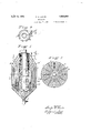
- Fig. 1 is a vertical section through an illustrative embodiment of the invention
- Fig. 21 s a section along the line 22 of Fig. 1
- Fig. 3 is a sectionalong the line 33 of Fig. 1
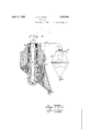
- Fig. 4 is a vertical section throu h a modification.
- re erence character 1 indicatescs a cylindrical. casing that is provided with an upper conically shaped portion 1' and the bottom portion is also preferably reduced and a valve 2 is located in an outlet leading away from the bottom of the casin
- a cylinder 3 extends downwardly from t e upper end of the casing 1 and the upper portion thereof is perforated, as indicated at 4.
- the upper portion may be made of a wire mesh, for example, to provide the perforations.
- An inclined tangential inlet 5 passes through the conical upper portion 1' of the casing and enters the upper end of the perforated portion 4 of the cylinder 3, so that the incoming material will follow. a helical path, and fill the space between the walls when it is introduced into the separator through a nozzle of proper size and position.
- low core 6 is located in the cylinder 3 and is tapered from near the middle portion toward both ends to provide annular spaces of changing cross-sectional area between the core and the cylinder 3.
- the lower end of the cylinder 3 is closed, as shown at 7.
- An outlet 8 ex- 5 tends from the top of the casing 1 and is conthrough the core 6.
- Concentric partitions 9, that are circular in cross-section, are located between the casing 1 and cylinder 3. These partitions are of different sizes and the upper ends 9' are coninected to the upper end of the opening cally shaped and terminate in contact with the outside surface of the perforated portion 4 of the cylinder 3, thus providing annular conduits from the perforated portion 4 that extend downwardly in the casing 1.
- Radial partitions 10 are also provided between the cylinder 3 and easing 1. The partitions 9 and 10 terminate approximately at the same level as the lower end of the cylinder 3, leaving a space for the collection of dust in the lower portion of thecasing 1.
- the dust may be permitted to accumlate to a suflicient depth to close the lower ends of the dust conduits formed by the partitions 9 so as to provide dead zones in which the dust settles by stopping all movement of the gas, air, vapor or steam, from which the dust or solid materialis being separated and preventing currents leaving perforations at one level and re-entering at another level.
- the cylinder 3 extends through the sloping bottom of the casing 1. Also a helical partition 11 is located in the space between the perforated portion 4 of the cylinder 3'and the core 6, so that the dust laden gas that enters through the inlet 5 follows a spiral path in this space and fills the passage.
- the dust laden fluid may be -passed through a cyclone separator of well known type 12 before it enters the pipe 5.
- the dust laden gas enters the cyclone separator 12 through the inlet 13 and the major portion of the coarser solid particles are separated and withdrawn through the outlet 14.
- the pipe 5 extends into the cyclone separator 12 some distance below the upper end thereof and the gas that has been partially freed from solid materials enters this pipe from the cyclone separator and then passes to the dust separator above described.
- the operation is as follows:
- Dust laden fluid such as gas, or air, or the like, enters tangentially from the pipe 5 into the widest portion of the space between the perforated portion 40f the cylinder 3 and the core 6, filling the space, and passes spirally around in this space with a whirling motion so that the coarsest particles are thrown out through the perforations into the uppermost dust conduit, the next smaller size of dust .or solid particles is thrown into the next lower conduit and so on toward the bottom of the perforated portion where the finest dust is thrown out.
- Dust laden fluid such as gas, or air, or the like
- the fluid passing helically downwardly through the space that is decreasing in size and filling the space has its velocity increased, so that it is greatest at the point where the wall of the core 6 is thickest; the result is that the finest particles are thrown out at the narrowest space where the velocity is greatest.
- the velocity is thereby converted into pressure to minimize the over-all pressure drop.
- the flow passage is made equivalent to an annular Venturi tube.
- the cleaned fluid then passes through the opening in the core 6 and out through the outlet 8.
- the increasing velocity of the whirling fluid over the perforated walls may be secured by using a cylindrical core 6 with a conical tube 3, or by other geometrical combinations, without departing from the invention. Also the decreasing velocity following completion of dust separation at the maximum velocity may be omitted when the overall loss of pressure through the apparatus is of no consequence.
- a separator comprising a casing, intersecting partitions in said casing with portions extending longitudinally of said casing, and having alined openings into the spaces between the partitions, and means to project material at different velocities into the spaces between said partitions.
- a separator comprising a casing, intersecting partitions in said casing, some of which are concentric with each other, having aligned openings into spaces between the partitions, and means to project material at different velocities into the spaces between said partitions.
- a separator comprising a casing, circular and radial partitions in the said casing, some of which are concentric with each other, having aligned openings into spaces between the partitions, and means to project material at different velocities into the spaces between said partitions.
- a separator comprising a cylindrical casing having a conically shaped end portion, intersecting partitions in said casing having aligned openings into spaces between the partitions, and means to project material at different velocities into the spaces between said partitions.
- a separator a casing, a perforated cylinder in said casing, circular partitions around said cylinder with reduced ends contacting with said cylinder at diflerent points, and means to project tangentially into said cylinder fluid in one phase laden with particles in another phase.
- a separator a casing, a perforated cylinder in said casing, a core in said cylinder tapered in two directions, and means to project tangentially into said cylinder fluid iii1 one phase laden with particles in another p ase.
- a separator In a separator, a. casing, a perforated cylinder in said casing, a hollow core in said cylinder tapered in two directions, and means to project tangentially into said cylinder fluid in one phase laden with particles in another phase.
- a separator a casing, a perforated cylinder in said casing, a core in said cylinder providing a restricted annular space intermediate the ends of the cylinder, anli means to project tangentially into said cylinder fluid in one phase laden with particles in another phase.
- a perforated wall means forming a fluid passage decreasing in size along one side of said wall, and separated chutes along the other side of said wall, and partitions in said chutes.
- a perforated wall means forming a fluid passage decreasing in size along one side of said wall, and then increas ing in size to produce a Venturi effect and separated chutes along the other side of said wall, and partitions in said chutes.
- a cylindrically shaped perforated wall means to pass fluid in one phase laden with particles in another phase at an increasing velocity along one side of said wall, and'separated chutes comprising cylinders concentric with said wall and with each other along the other side of said wall.
Description
C. E. LUCKE 'A IFil 12, 1932.
SEPARATOR Filed Aug. 7, 1928 2 Sheets-Sheet l INVENTOR $3?! 6 0 x9 ui/ ATTORNEYS April 12, 1932. c E K 1,853,868
Q I a sEPAR'ATbR Filed Aug. '7, 1928 2 Sheets- Sheet 2 I /ZBY HEILENTOR {e M WATORNEYS P a tented Apr. 12, 1932 UNITED STATES PATENT OFFICE CHARLES E. LUCKE, OF NEW YORK, N. Y., ASSIGNOR TO THE BAIBCOCK & WILCOX COM- PAN'Y, OF BAYONNE, NEW JERSEY, A CORPORATION OF NEW ."fIFJRSIIilY- SEPARAT OR Application ma August 7, 1928. Serial No. 297,950.
This invention relates to a separator. By this invention dust or solid particles may be separated from gas, air, or vapor or the like, or solids may be separated from liquids by centrifugal force without causing a large draft loss or pressure dro due to friction through the separator. Liquid drops may also be separated from vapors or gases. The word dust will be used to include both fine l0 and coarse particles.
The invention will be understood from the description in connection with the accompanying drawings, in which Fig. 1 is a vertical section through an illustrative embodiment of the invention; Fig. 21s a section along the line 22 of Fig. 1; Fig. 3 is a sectionalong the line 33 of Fig. 1; and Fig. 4 is a vertical section throu h a modification.
In the drawings re erence character 1 indicatcs a cylindrical. casing that is provided with an upper conically shaped portion 1' and the bottom portion is also preferably reduced and a valve 2 is located in an outlet leading away from the bottom of the casin A cylinder 3 extends downwardly from t e upper end of the casing 1 and the upper portion thereof is perforated, as indicated at 4. The upper portion may be made of a wire mesh, for example, to provide the perforations. An inclined tangential inlet 5 passes through the conical upper portion 1' of the casing and enters the upper end of the perforated portion 4 of the cylinder 3, so that the incoming material will follow. a helical path, and fill the space between the walls when it is introduced into the separator through a nozzle of proper size and position. A 1101-.
low core 6 is located in the cylinder 3 and is tapered from near the middle portion toward both ends to provide annular spaces of changing cross-sectional area between the core and the cylinder 3. The lower end of the cylinder 3 is closed, as shown at 7. An outlet 8 ex- 5 tends from the top of the casing 1 and is conthrough the core 6.
Concentric partitions 9, that are circular in cross-section, are located between the casing 1 and cylinder 3. These partitions are of different sizes and the upper ends 9' are coninected to the upper end of the opening cally shaped and terminate in contact with the outside surface of the perforated portion 4 of the cylinder 3, thus providing annular conduits from the perforated portion 4 that extend downwardly in the casing 1. Radial partitions 10 are also provided between the cylinder 3 and easing 1. The partitions 9 and 10 terminate approximately at the same level as the lower end of the cylinder 3, leaving a space for the collection of dust in the lower portion of thecasing 1. i
The dust may be permitted to accumlate to a suflicient depth to close the lower ends of the dust conduits formed by the partitions 9 so as to provide dead zones in which the dust settles by stopping all movement of the gas, air, vapor or steam, from which the dust or solid materialis being separated and preventing currents leaving perforations at one level and re-entering at another level.
In the modification shown in Fig. 4 the lower ends of the partitions 9 are made sloping to correspond to the sloping lower end of the casing 1 and the valve 2 is located in an outlet from the casing.
In this modificationthe cylinder 3 extends through the sloping bottom of the casing 1. Also a helical partition 11 is located in the space between the perforated portion 4 of the cylinder 3'and the core 6, so that the dust laden gas that enters through the inlet 5 follows a spiral path in this space and fills the passage.
In either modification of the invention the dust laden fluid may be -passed through a cyclone separator of well known type 12 before it enters the pipe 5. The dust laden gas enters the cyclone separator 12 through the inlet 13 and the major portion of the coarser solid particles are separated and withdrawn through the outlet 14. The pipe 5 extends into the cyclone separator 12 some distance below the upper end thereof and the gas that has been partially freed from solid materials enters this pipe from the cyclone separator and then passes to the dust separator above described. The operation is as follows:
Dust laden fluid such as gas, or air, or the like, enters tangentially from the pipe 5 into the widest portion of the space between the perforated portion 40f the cylinder 3 and the core 6, filling the space, and passes spirally around in this space with a whirling motion so that the coarsest particles are thrown out through the perforations into the uppermost dust conduit, the next smaller size of dust .or solid particles is thrown into the next lower conduit and so on toward the bottom of the perforated portion where the finest dust is thrown out. The fluid passing helically downwardly through the space that is decreasing in size and filling the space, has its velocity increased, so that it is greatest at the point where the wall of the core 6 is thickest; the result is that the finest particles are thrown out at the narrowest space where the velocity is greatest. After the fluid passes the most restricted space or smallest flow area between the cylinder 3 and core 6, it enters a space of gradually increasing cross-section and fills the space, thus permitting its velocity to decrease. The velocity is thereby converted into pressure to minimize the over-all pressure drop. In this way the flow passage is made equivalent to an annular Venturi tube. The cleaned fluid then passes through the opening in the core 6 and out through the outlet 8.
The increasing velocity of the whirling fluid over the perforated walls may be secured by using a cylindrical core 6 with a conical tube 3, or by other geometrical combinations, without departing from the invention. Also the decreasing velocity following completion of dust separation at the maximum velocity may be omitted when the overall loss of pressure through the apparatus is of no consequence.
When liquid drops suspended in vapors or gases or fogs, are passed through the separator, they are removed in a similar manner.
I claim:
1. A separator comprising a casing, intersecting partitions in said casing with portions extending longitudinally of said casing, and having alined openings into the spaces between the partitions, and means to project material at different velocities into the spaces between said partitions.
2. A separator comprising a casing, intersecting partitions in said casing, some of which are concentric with each other, having aligned openings into spaces between the partitions, and means to project material at different velocities into the spaces between said partitions.
3. A separator comprising a casing, circular and radial partitions in the said casing, some of which are concentric with each other, having aligned openings into spaces between the partitions, and means to project material at different velocities into the spaces between said partitions.
4. A separator comprising a cylindrical casing having a conically shaped end portion, intersecting partitions in said casing having aligned openings into spaces between the partitions, and means to project material at different velocities into the spaces between said partitions.
5. In a separator, a casing, a perforated cylinder in said casing, circular partitions around said cylinder with reduced ends contacting with said cylinder at diflerent points, and means to project tangentially into said cylinder fluid in one phase laden with particles in another phase.
6. In a separator, a casing, a perforated cylinder in said casing, a core in said cylinder tapered in two directions, and means to project tangentially into said cylinder fluid iii1 one phase laden with particles in another p ase.
7 In a separator, a. casing, a perforated cylinder in said casing, a hollow core in said cylinder tapered in two directions, and means to project tangentially into said cylinder fluid in one phase laden with particles in another phase.
8. In a separator, a casing, a perforated cylinder in said casing, a core in said cylinder providing a restricted annular space intermediate the ends of the cylinder, anli means to project tangentially into said cylinder fluid in one phase laden with particles in another phase.
9. In a separator, a perforated wall, means forming a fluid passage decreasing in size along one side of said wall, and separated chutes along the other side of said wall, and partitions in said chutes.
10. In a separator, a perforated wall, means forming a fluid passage decreasing in size along one side of said wall, and then increas ing in size to produce a Venturi effect and separated chutes along the other side of said wall, and partitions in said chutes.
11. In a separator, a cylindrically shaped perforated wall, means to pass fluid in one phase laden with particles in another phase at an increasing velocity along one side of said wall, and'separated chutes comprising cylinders concentric with said wall and with each other along the other side of said wall.
, CHARLES E. LUCKE.
Priority Applications (1)
| Application Number | Priority Date | Filing Date | Title |
|---|---|---|---|
| US297956A US1853868A (en) | 1928-08-07 | 1928-08-07 | Separator |
Applications Claiming Priority (1)
| Application Number | Priority Date | Filing Date | Title |
|---|---|---|---|
| US297956A US1853868A (en) | 1928-08-07 | 1928-08-07 | Separator |
Publications (1)
| Publication Number | Publication Date |
|---|---|
| US1853868A true US1853868A (en) | 1932-04-12 |
Family
ID=23148414
Family Applications (1)
| Application Number | Title | Priority Date | Filing Date |
|---|---|---|---|
| US297956A Expired - Lifetime US1853868A (en) | 1928-08-07 | 1928-08-07 | Separator |
Country Status (1)
| Country | Link |
|---|---|
| US (1) | US1853868A (en) |
Cited By (2)
| Publication number | Priority date | Publication date | Assignee | Title |
|---|---|---|---|---|
| US2473602A (en) * | 1945-04-25 | 1949-06-21 | Lavigne Jean Loumiet Et | Fluid separator |
| US20150238980A1 (en) * | 2012-11-16 | 2015-08-27 | Corning Incorporated | Integrated cyclone separation device |
-
1928
- 1928-08-07 US US297956A patent/US1853868A/en not_active Expired - Lifetime
Cited By (3)
| Publication number | Priority date | Publication date | Assignee | Title |
|---|---|---|---|---|
| US2473602A (en) * | 1945-04-25 | 1949-06-21 | Lavigne Jean Loumiet Et | Fluid separator |
| US20150238980A1 (en) * | 2012-11-16 | 2015-08-27 | Corning Incorporated | Integrated cyclone separation device |
| US9636691B2 (en) * | 2012-11-16 | 2017-05-02 | Corning Incorporated | Integrated cyclone separation device |
Similar Documents
| Publication | Publication Date | Title |
|---|---|---|
| US4148735A (en) | Separator for use in boreholes of limited diameter | |
| US2214658A (en) | Steam separator | |
| US2511967A (en) | Gas and liquto separator | |
| US2201301A (en) | Centrifugal separating device | |
| US6190543B1 (en) | Cyclonic separator | |
| US3359708A (en) | Gas and liquid separating apparatus | |
| US2917131A (en) | Cyclone separator | |
| CA2705127C (en) | Revolution vortex tube gas/liquids separator | |
| US1958577A (en) | Apparatus for dust separation | |
| GB332405A (en) | Improvements in centrifugal apparatus for dust extraction | |
| US3636682A (en) | Cyclone separator | |
| US4278550A (en) | Fluid separator | |
| US3546854A (en) | Centrifugal separator | |
| US3433362A (en) | Cyclone purifier | |
| US2547190A (en) | Oil and gas separator | |
| US2975896A (en) | Hydrocyclone for fibres suspension | |
| US3324634A (en) | Vapor-liquid separator | |
| US2290664A (en) | Separating apparatus | |
| US2580317A (en) | Purger | |
| US429347A (en) | Dust-collector | |
| US2681150A (en) | Water separator | |
| US2999593A (en) | Classification of materials | |
| US1853868A (en) | Separator | |
| US1505744A (en) | Separator | |
| US1930476A (en) | Line separator and grader |