US1853864A - Clutch and motor construction - Google Patents
Clutch and motor construction Download PDFInfo
- Publication number
- US1853864A US1853864A US198093A US19809327A US1853864A US 1853864 A US1853864 A US 1853864A US 198093 A US198093 A US 198093A US 19809327 A US19809327 A US 19809327A US 1853864 A US1853864 A US 1853864A
- Authority
- US
- United States
- Prior art keywords
- clutch
- clutch member
- hood
- rotor
- electro
- Prior art date
- Legal status (The legal status is an assumption and is not a legal conclusion. Google has not performed a legal analysis and makes no representation as to the accuracy of the status listed.)
- Expired - Lifetime
Links
Images
Classifications
-
- F—MECHANICAL ENGINEERING; LIGHTING; HEATING; WEAPONS; BLASTING
- F16—ENGINEERING ELEMENTS AND UNITS; GENERAL MEASURES FOR PRODUCING AND MAINTAINING EFFECTIVE FUNCTIONING OF MACHINES OR INSTALLATIONS; THERMAL INSULATION IN GENERAL
- F16D—COUPLINGS FOR TRANSMITTING ROTATION; CLUTCHES; BRAKES
- F16D67/00—Combinations of couplings and brakes; Combinations of clutches and brakes
- F16D67/02—Clutch-brake combinations
- F16D67/06—Clutch-brake combinations electromagnetically actuated
Definitions
- This invention relates to electric motors of the type and kind shown and descrlbed in my Patent No. 1,665,742 dated April 10, 1928, wherein electrically-controlled clutch means .6 is provided to increase the starting torque and effect starting with a smallamount of electric current, the primary purpose bemg to safeguard operation of the motor and to avoid objectionable drain and marked fluctuation of current in starting. is an improvement involving a similar electricallv-controlled clutch.
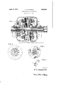
- Fig. 1 1s a sectional view longitudinally of a motor embodying my improvements.
- Fig. 2 is an end view of the ring her on line 22 of Fig. 1.
- Fig. 3 is an end view and cross section on line 3-3 of Fig. 1, showing the centrifugal switch members and triplex cup for controlling the starting winding.
- Fig. 4 is a perspective view of one of the switch members.
- the motor as shown, comprises a stator S having a main winding which may be divided to form two separate sets of coils 2 and 3, respectively, both of which may be used for running purposes, and one cut out for an interval in starting operations.
- a separate starting winding 4 is also used, and this winding is in circuit only for an interval or until a set of centrifugal switch elements 5 is thrown out of contact from a three part or triplex switch cup 6 stationed at one side of the rotor R carrying the switch elements 5.
- each element or pivoted arm 5 having a pair
- Rotor R is free to revolve on motor shaft 11 and carries a dished clutch member 12 at one side thereof.
- a sliding cone or beveled clutch member 14 is keyed to shaft 11 and faced with leather or other friction material to coact with the dished member 12 in driving the shaft when the motor is running under load.
- a flat ring or plate 15 is affixed to or forms an integral part of clutch member 1 1, being preferably spaced apart from hub 16 and also the friction head thereon but connected therewith by radial ribs 17 which serve as fan blades when shaft 11 is in motion.
- a coiled spring 18 is sleeved loosely on shaft 11 between a fixed collar 19 and hub 16, there by maintaining friction engagement between the respective clutch members at all times except in starting.
- interval spring 18 is compressed and cone member 1 1 is disenaged from member 12 by electro-magnetic pull on plate 15 which is spaced apart from a magnet coil 20 confined within an annular channel 21 formed by a pair of concentric ribs 22 extending inwardly from the end wall of hood 23 of the motor.
- the ribbed and channeled'portion of hood-23 is of substantially the same area and diameter as the plate or ring armature 15, and a circular space 2 1 surrounds shaft 11 opposite a corresponding opening 25 between hub 16 and the inner edge of the ring-shaped plate or armature 15, thereby forming an annular air intake passage for the fan blades 17.
- Hood 23 contains air inlet openings 26 around the bearing 27 which communicate with space 24-, and the other end hood 23 of the motor is also provided with openings 28 to promote circulation of the air through the motor.
- a heavy coiled spring 29 adapted to seat or bear against bearing 27 or the inner side of hood 23 and to be engaged by hub 16 or a separate plate 30 interposed between the hub and said spring.
- This buffer spring 29 is preferably not compressed or under tension when inactive but is spaced apart from the ub or plate 30 at the beginning of the releasing movement of clutch member 14 thus permitting this clutch member to be freely actu- 15 ated by the magnet.
- the buffer spring is engaged and supplements the pressure of spring 18 to prevent the ring armature or plate 15 from rubbing against magthe vibration is counter-acted and reduced to a minimum and obectionable sounds prevented.
- an electric motor including a perforated hood, a drive shaft and a rotor freely rotatable on said drive shaft, an electro magneticclutch. comprising an electro-magnetic coil mounted on said hood, a shiftable springpressed clutch member connected with the shaft, a complementarv clutch member connected. to the rotor and a ring-shaped armature cooperating with said electro-magnetic coil, and connected to said shiftable clutch member by means of radial ribs extending 1from the clutching part of said clutch mem- 2.
- an electro-magnetic clutch comprising-an electro-magnetic coil mounted in a channeled portion of said hood encircling the perforated part thereof centrally with respect to said shaft.'a clutch member fixed to said rotor. a shiftable clutch member mounted on said shaft having a clutching part and a ring-shaped armature connected therewith, and spring means for holding said clutch members normally engaged.
- an electro-magnetic clutch comprising an electro-magnetic coil supported within a cylindrical channel formed by parallel Walls integrally extending from the inner side of the hood and centrally with respect to the drive shaft, a clutch member mounted on said rotor, a shiftable clutch member having a clutching part and a ring-shaped armature connected therewith by radial ribs, spring means for l ormal engagement of said clutch, and buil'er means for said shiftable clutch member coacting with said spring means to counteract a shift- N rated hood, a drive shaft ing movement of said clutch member by said electro-magnetic coil.
- an electro-magnetic clutch in which said buffer means consists of a heavy s ring slightly spaced apart from said shif table clutching member.
- an eleotro-magnetic clutch comprising ari electro-magnetic coil mounted in a channeled portion of said hood extending inwardly from the wall thereof centrally with respect to said shaft, a clutch member fixed to said rotor, a shiftable clutch member associated with said rotor, clutch member having a clutching part and a ring-shaped armature connected therewith by ribs of substantial surface area, and spring means for holding said clutch members normally engaged.
- an electro-magnetic clutch comprising an electro-magnetic coil mounted in a channeled portion of said hood centrally with respect to said shaft, a clutch member fixed to said rotor, a shiftable clutch member associated with said rotor clutch member having a clutching part and a ring-shaped armature connected therewith by ribs of substantial surface area, and spring means for normalengagement of said clutch.
Description
April 12; 1932.
F. S. KINGSTON CLUTCH AND MOTOR CONSTRUCTION Filed June 11, 927
awuewtoz 7 '5- KINEETUN Patented Apr. 12, 1932 UNITEDSTATES PATENT oreica FREDERICK S. KINGSTON, OE WAREEN, 01-110, ASSIGNOR TO THE SUNLIGHT ELECTRICAL MANUFACTURING COMPANY OF WARREN, OHIO, A CORPORATION OF OHIO GLTITCHI AND MOTOR CONSTRUCTIQN Application filed June 11, 19-27. Serial. No. 198,093.
This invention relates to electric motors of the type and kind shown and descrlbed in my Patent No. 1,665,742 dated April 10, 1928, wherein electrically-controlled clutch means .6 is provided to increase the starting torque and effect starting with a smallamount of electric current, the primary purpose bemg to safeguard operation of the motor and to avoid objectionable drain and marked fluctuation of current in starting. is an improvement involving a similar electricallv-controlled clutch. The coil for the clutch is mounted within a channeled seat n one end cap for the motor, and the clutch 18 provided with a flat ring armature opposite this coil, and the movement of this armature toward the coil is under the control of two springs, one to effect a clutching action and the other to act as a cushioning buffer and stop to prevent vibration and noise when an alternating current, say 60 cycle A. C.. is passing through the coil, all as hereinafter shown and described and more concisely set forth in the claims. 25 In the accompanying drawings, Fig. 1 1s a sectional view longitudinally of a motor embodying my improvements. Fig. 2 is an end view of the ring her on line 22 of Fig. 1. Fig. 3 is an end view and cross section on line 3-3 of Fig. 1, showing the centrifugal switch members and triplex cup for controlling the starting winding. Fig. 4 is a perspective view of one of the switch members.
The motor, as shown, comprises a stator S having a main winding which may be divided to form two separate sets of coils 2 and 3, respectively, both of which may be used for running purposes, and one cut out for an interval in starting operations. A separate starting winding 4 is also used, and this winding is in circuit only for an interval or until a set of centrifugal switch elements 5 is thrown out of contact from a three part or triplex switch cup 6 stationed at one side of the rotor R carrying the switch elements 5. These elements are pivotally mounted upon a disk or ring 7 and are thrown inwardly by springs 8 to establish contact with cup 6, 50 each element or pivoted arm 5 having a pair The present device I armature and clutch memg" ofloosely pivoted pieces 9--9 at their free ends, and each piece 9 having two contact extremities 1010 adapted to span the gaps between the sections of the cup when in a bridging position in respect thereto and adapted to contact at four places on the cup sections, thereby assuring good conductivity for the current and absence of sparking.
Rotor R is free to revolve on motor shaft 11 and carries a dished clutch member 12 at one side thereof. A sliding cone or beveled clutch member 14: is keyed to shaft 11 and faced with leather or other friction material to coact with the dished member 12 in driving the shaft when the motor is running under load. A flat ring or plate 15 is affixed to or forms an integral part of clutch member 1 1, being preferably spaced apart from hub 16 and also the friction head thereon but connected therewith by radial ribs 17 which serve as fan blades when shaft 11 is in motion. A coiled spring 18 is sleeved loosely on shaft 11 between a fixed collar 19 and hub 16, there by maintaining friction engagement between the respective clutch members at all times except in starting. In that interval spring 18 is compressed and cone member 1 1 is disenaged from member 12 by electro-magnetic pull on plate 15 which is spaced apart from a magnet coil 20 confined within an annular channel 21 formed by a pair of concentric ribs 22 extending inwardly from the end wall of hood 23 of the motor. The ribbed and channeled'portion of hood-23 is of substantially the same area and diameter as the plate or ring armature 15, and a circular space 2 1 surrounds shaft 11 opposite a corresponding opening 25 between hub 16 and the inner edge of the ring-shaped plate or armature 15, thereby forming an annular air intake passage for the fan blades 17. Hood 23 contains air inlet openings 26 around the bearing 27 which communicate with space 24-, and the other end hood 23 of the motor is also provided with openings 28 to promote circulation of the air through the motor.
ll find that in using an alternatingcurrent to energize magnet coil 20 and draw the ring armature 15 of clutch member 1 1 counter to the pressure of spring 18, a certain amount of 20 net coil 20 and ribs 22, and
vibration will result and cause an objectionable sound or noise. This is obviated by using a resilient bufier for clutch member 14:,
which in the present instance is in the form 5 of a heavy coiled spring 29 adapted to seat or bear against bearing 27 or the inner side of hood 23 and to be engaged by hub 16 or a separate plate 30 interposed between the hub and said spring. This buffer spring 29 is preferably not compressed or under tension when inactive but is spaced apart from the ub or plate 30 at the beginning of the releasing movement of clutch member 14 thus permitting this clutch member to be freely actu- 15 ated by the magnet. However as soon as the clutch members are separated the buffer spring is engaged and supplements the pressure of spring 18 to prevent the ring armature or plate 15 from rubbing against magthe vibration is counter-acted and reduced to a minimum and obectionable sounds prevented.
What I claim is: 1. In an electric motor including a perforated hood, a drive shaft and a rotor freely rotatable on said drive shaft, an electro magneticclutch. comprising an electro-magnetic coil mounted on said hood, a shiftable springpressed clutch member connected with the shaft, a complementarv clutch member connected. to the rotor and a ring-shaped armature cooperating with said electro-magnetic coil, and connected to said shiftable clutch member by means of radial ribs extending 1from the clutching part of said clutch mem- 2. In an electric motor including a perforated hood, a drive shaft and a rotor freely rotatable on said drive shaft, an electro-magnetic clutch comprising-an electro-magnetic coil mounted in a channeled portion of said hood encircling the perforated part thereof centrally with respect to said shaft.'a clutch member fixed to said rotor. a shiftable clutch member mounted on said shaft having a clutching part and a ring-shaped armature connected therewith, and spring means for holding said clutch members normally engaged.
3., In an electric motor including a perforated hood, a drive shaft and a rotor freely rotatable on said drive shaft, an electro-magnetic clutch, comprising an electro-magnetic coil supported within a cylindrical channel formed by parallel Walls integrally extending from the inner side of the hood and centrally with respect to the drive shaft, a clutch member mounted on said rotor, a shiftable clutch member having a clutching part and a ring-shaped armature connected therewith by radial ribs, spring means for l ormal engagement of said clutch, and buil'er means for said shiftable clutch member coacting with said spring means to counteract a shift- N rated hood, a drive shaft ing movement of said clutch member by said electro-magnetic coil.
4. In an electric motor including a perforated hood, adrive shaft and a rotor freely rotatable on said drive shaft, an electro-magnetic clutch according to claim 3, in which said buffer means consists of a heavy s ring slightly spaced apart from said shif table clutching member.
5. In an electric motor including a perfoand a rotor freely rotatable on said drive shaft, an eleotro-magnetic clutch, comprising ari electro-magnetic coil mounted in a channeled portion of said hood extending inwardly from the wall thereof centrally with respect to said shaft, a clutch member fixed to said rotor, a shiftable clutch member associated with said rotor, clutch member having a clutching part and a ring-shaped armature connected therewith by ribs of substantial surface area, and spring means for holding said clutch members normally engaged.
6. In an electric motor including a perforated hood, a drive shaft and a rotor freely rotatable on said drive shaft, an electro-magnetic clutch comprising an electro-magnetic coil mounted in a channeled portion of said hood centrally with respect to said shaft, a clutch member fixed to said rotor,a shiftable clutch member associated with said rotor clutch member having a clutching part and a ring-shaped armature connected therewith by ribs of substantial surface area, and spring means for normalengagement of said clutch.
In testimony whereof I afiix my signature.
FREDERICK S. KINGSTON.
Priority Applications (1)
| Application Number | Priority Date | Filing Date | Title |
|---|---|---|---|
| US198093A US1853864A (en) | 1927-06-11 | 1927-06-11 | Clutch and motor construction |
Applications Claiming Priority (1)
| Application Number | Priority Date | Filing Date | Title |
|---|---|---|---|
| US198093A US1853864A (en) | 1927-06-11 | 1927-06-11 | Clutch and motor construction |
Publications (1)
| Publication Number | Publication Date |
|---|---|
| US1853864A true US1853864A (en) | 1932-04-12 |
Family
ID=22731952
Family Applications (1)
| Application Number | Title | Priority Date | Filing Date |
|---|---|---|---|
| US198093A Expired - Lifetime US1853864A (en) | 1927-06-11 | 1927-06-11 | Clutch and motor construction |
Country Status (1)
| Country | Link |
|---|---|
| US (1) | US1853864A (en) |
Cited By (5)
| Publication number | Priority date | Publication date | Assignee | Title |
|---|---|---|---|---|
| US2441836A (en) * | 1944-06-19 | 1948-05-18 | Soundscriber Corp | Rapid start and stop clutch mechanism for phonographs |
| US2607445A (en) * | 1948-03-31 | 1952-08-19 | Steel Products Eng Co | Braking mechanism |
| DE1199550B (en) * | 1958-01-31 | 1965-08-26 | Eaton Mfg Co | Mechanical, automatic and steplessly acting adjusting device for the air gap of the armature disk of an electromagnetically operated friction clutch or brake |
| DE1221500B (en) * | 1962-04-04 | 1966-07-21 | Olympia Werke Ag | Friction clutch and brake |
| US3662197A (en) * | 1970-11-12 | 1972-05-09 | Gen Electric | Combination motor-clutch apparatus |
-
1927
- 1927-06-11 US US198093A patent/US1853864A/en not_active Expired - Lifetime
Cited By (5)
| Publication number | Priority date | Publication date | Assignee | Title |
|---|---|---|---|---|
| US2441836A (en) * | 1944-06-19 | 1948-05-18 | Soundscriber Corp | Rapid start and stop clutch mechanism for phonographs |
| US2607445A (en) * | 1948-03-31 | 1952-08-19 | Steel Products Eng Co | Braking mechanism |
| DE1199550B (en) * | 1958-01-31 | 1965-08-26 | Eaton Mfg Co | Mechanical, automatic and steplessly acting adjusting device for the air gap of the armature disk of an electromagnetically operated friction clutch or brake |
| DE1221500B (en) * | 1962-04-04 | 1966-07-21 | Olympia Werke Ag | Friction clutch and brake |
| US3662197A (en) * | 1970-11-12 | 1972-05-09 | Gen Electric | Combination motor-clutch apparatus |
Similar Documents
| Publication | Publication Date | Title |
|---|---|---|
| US4095922A (en) | Electro-mechanical device | |
| US2096621A (en) | Mounting for electric motors and the like | |
| US3241742A (en) | Fan | |
| US1853864A (en) | Clutch and motor construction | |
| US1763104A (en) | Variable-speed alpha c motors | |
| US2372064A (en) | Centrifugal device | |
| US3033049A (en) | Fan drive and mounting | |
| US2156047A (en) | Driving connection | |
| US4135612A (en) | Electric motor with air cooled clutch and brake | |
| US3038109A (en) | Braking systems for electrical motors | |
| US1948037A (en) | Electric motor | |
| US1988922A (en) | Clutch for dynamo-electric machines | |
| US2713970A (en) | Silent, readily-serviced electric fan construction | |
| US3662197A (en) | Combination motor-clutch apparatus | |
| GB1366978A (en) | Electromagnetic clutches | |
| US736461A (en) | Electric motor and brake. | |
| US3582697A (en) | Combination motor-clutch apparatus | |
| US3229796A (en) | Adjustable constant speed magnetic clutch | |
| US1910610A (en) | Dynamo-electric machine | |
| US1380134A (en) | Speed-controlling device for motors | |
| US1357403A (en) | Centrifugal governor | |
| US1976598A (en) | Induction motor | |
| US2454314A (en) | Vacuum cleaner | |
| US2949991A (en) | Friction clutch | |
| US3128865A (en) | Centrifugal clutch |