US1853834A - Toy firearm - Google Patents
Toy firearm Download PDFInfo
- Publication number
- US1853834A US1853834A US559999A US55999931A US1853834A US 1853834 A US1853834 A US 1853834A US 559999 A US559999 A US 559999A US 55999931 A US55999931 A US 55999931A US 1853834 A US1853834 A US 1853834A
- Authority
- US
- United States
- Prior art keywords
- hammer
- cap
- anvil
- strip
- trigger
- Prior art date
- Legal status (The legal status is an assumption and is not a legal conclusion. Google has not performed a legal analysis and makes no representation as to the accuracy of the status listed.)
- Expired - Lifetime
Links
- 238000004880 explosion Methods 0.000 description 7
- 239000004744 fabric Substances 0.000 description 4
- 238000010276 construction Methods 0.000 description 2
- 239000000463 material Substances 0.000 description 2
- USXDFAGDIOXNML-UHFFFAOYSA-N Fulminate Chemical compound [O-][N+]#[C-] USXDFAGDIOXNML-UHFFFAOYSA-N 0.000 description 1
- 239000002360 explosive Substances 0.000 description 1
- 238000010304 firing Methods 0.000 description 1
- 230000000979 retarding effect Effects 0.000 description 1
Images
Classifications
-
- F—MECHANICAL ENGINEERING; LIGHTING; HEATING; WEAPONS; BLASTING
- F41—WEAPONS
- F41C—SMALLARMS, e.g. PISTOLS, RIFLES; ACCESSORIES THEREFOR
- F41C3/00—Pistols, e.g. revolvers
- F41C3/06—Cap-firing pistols, e.g. toy pistols
- F41C3/08—Cap-firing pistols, e.g. toy pistols with band supply
Definitions
- the present invention relates to pistols, cannons and other toy fire arms wherein a continuous roll of caps is employed which are automatically fed to exploding position.
- the usual cap strip comprises two pieces of thin paper carrying the fulminate and where an ordinary fiat anvil and fiat hammer were employed, the force of the explosion tended to cause the cap strip to adhere to the anvil.
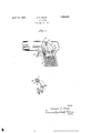
- Figure 1 is a side elevation partly broken away showing the construction of actuated mechanism set forth in my aforesaid application and also illustrating in end elevation the contour of the hammer.
- Figure 2 is a perspective view of the ham- 5 mer showing the striking face.
- the striking face of the hammer as shown is provided with a plurality of transverse corrugations 17. These corrugations may be of any desired depth, but I preferably make them relatively shallow.
- the faces of the ridges constituting the striking face of the hammer are flattened as at 18, while the edges of the ridges and corrugations are sharp as shown at 19.
- the purpose of having the flat faces 18 is to insure that the cap will be exploded, While in making the ridges and corrugations with sharp edges 19, the corrugations will be forced into the cap material.
- the cap strip is usually formed of two thin strips of soft paper which are pasted together, so that when the striking face of the hammer of the present invention engages such laminated strip, it will penetrate the strip. The force of the explosion will likewise cause the paper to expand somewhat, into the corrugated portions, so that a very firm frictional contact is obtained between the strip and the strik-' ing face and any possibility of the cap sticking to the anvil as where a flat face hammer and anvil are provided, is eliminated.
- An automatic fire arm having-an anvil, a hammer, a trigger, and means operable by actuation of the trigger for propellinga cap strip in position to be exploded on the anvil by the hammer, said hammerhaving a striking face formed with shallow corrugations, the ridges of which are'adapted to penetrate into the fabric of the cap strip and the furrowsto receivethe cap strip expanded upon explosion by thehammer, to frictionally engage the cap strip and move it away from the anvil-after eachexplosion of a cap and upon retraction of the hammer, said movement of the cap strip from the anvil being coincident with the feedingof the cap strip by said propelling means to the anvil.
- An automatic fire-arm having an anvil, a hammer, a trigger, and means operable by actuation of the trigger for automatically feeding successively caps of a strip into posit-ion to be exploded on the anvil by the hammer, said hammer having a corrugated striking area extending across the face of the hammer, the striking portions-of the area being flat with the ridges of the corrugations formed with sharp edges to bite into the fab ric of the cap strip and frictionally engage .the cap strip to move'it away from the anvil after explosion of a cap and 'upon retraction of the hammer, said movement of the cap strip from the anvil being coincident withtheoperation of the feeding means for feeding a cap of the strip successivelyto the anvil.
- An automatiofire arm having an anvil, ahammeryatrigger, and means operable by actuationof the trigger for propelling-a cap strip in position to be exploded on the anvil by the hammer, said hammer having a striking face formed with shallow corrugations, the edges'of the ridges of which areadapted topenetrate the fabric of the cap strip and the furrows to receive the cap strip expanded upon explosion bythe hammer, to frictionally engage the cap strip and move it away from the anvil after each explosion of a cap and upon retraction of the hammer.
- An automatic fire arm having an anvil
- a hammer a'trigger, and means operable by actuation of the trigger'for propelling a cap strip in position tobe exploded on the anvil by the hammer, said hammerhaving a striking face formed with shallow, transversely extending corrugations, the ridges of which are adapted to bite into the fabric of the cap strip and the zfurrows to receive the'cap strip
Description
E. S. PEAKE April 12, 1932.
TOY FIREARM Filed Aug. 28, 1951 3nventor B Jaw/am? 5. PM W MW, (lttomegs Patented Apr. 12, 1932 taste EDWARD S. PEAKE, OF WESTERVILLE, OHIO, ASSIGNOR TO THE KILGORE MFG. COM- PANY, OF WESTERVILLE, OHIO, A CORPORATION OF OHIO TOY FIREARM Application filed August 28, 1931.
The present invention relates to pistols, cannons and other toy fire arms wherein a continuous roll of caps is employed which are automatically fed to exploding position.
In my copending application Serial No.
478,713, filed August 29, 1930, there is disclosed a mechanism for feeding and exploding the caps in which upon actuation of the trigger, the caps are successively fed to an anvil and exploded by the hammer and I have found that with such a construction, it is necessary where the trigger is operated at a high rate or speed, to overcome any possibility of a cap sticking to the anvil and thereby retarding the successive feed of caps.
The usual cap strip comprises two pieces of thin paper carrying the fulminate and where an ordinary fiat anvil and fiat hammer were employed, the force of the explosion tended to cause the cap strip to adhere to the anvil.
I overcome this condition by providing the hammer with shallow corrugations with the edges of the furrows and ridges, however, sharply angled, so that the hammer will penetrate the layer and thus as the hammer is retracted upon actuation of the trigger, the frictional contact between the strip and the hammer will cause the strip to be drawn upwardly at the same time as the feeding mechanism acts to propel another cap into position.
It will be understood that when a cap is exploded, the explosive force will cause the layers of cap material to enter the corrugated portion of the hammer, so that a very strong frictional connection is obtained between the cap strip and the hammer which, as stated. ass sts the feed of the cap strip upon each retraction of the hammer, and no matter how frequent or rapid the trigger be actuated, there is no possibility of the feed jamming or of the caps sticking to the anvil.
In the drawings:
Figure 1 is a side elevation partly broken away showing the construction of actuated mechanism set forth in my aforesaid application and also illustrating in end elevation the contour of the hammer.
Figure 2 is a perspective view of the ham- 5 mer showing the striking face.
Serial No. 559,999.
14 and passes between two gripping members 15 and 16, which, upon operation of the trigger, grip the. cap strip and move a cap successively into firing position on the anvil.
It will be understood that at the same time as i the trigger is retracted and the cap strip propelled toward the anvil, that the hammer is likewise retracted.
The striking face of the hammer as shown is provided with a plurality of transverse corrugations 17. These corrugations may be of any desired depth, but I preferably make them relatively shallow. The faces of the ridges constituting the striking face of the hammer are flattened as at 18, while the edges of the ridges and corrugations are sharp as shown at 19. The purpose of having the flat faces 18 is to insure that the cap will be exploded, While in making the ridges and corrugations with sharp edges 19, the corrugations will be forced into the cap material.
It will be understood that the cap strip is usually formed of two thin strips of soft paper which are pasted together, so that when the striking face of the hammer of the present invention engages such laminated strip, it will penetrate the strip. The force of the explosion will likewise cause the paper to expand somewhat, into the corrugated portions, so that a very firm frictional contact is obtained between the strip and the strik-' ing face and any possibility of the cap sticking to the anvil as where a flat face hammer and anvil are provided, is eliminated.
It will, therefore, be seen that when the trigger is retracted after the explosion of a the trigger can be actuated with great rapidity and without fear of sticking.
It will be understood that instead of having the corrugations transversely of the ham mer face, they may be arranged longitudinally thereof, but I prefer to have the corrugated .area extend across the face of the hammer.
What I claim is:
1. An automatic fire arm having-an anvil, a hammer, a trigger, and means operable by actuation of the trigger for propellinga cap strip in position to be exploded on the anvil by the hammer, said hammerhaving a striking face formed with shallow corrugations, the ridges of which are'adapted to penetrate into the fabric of the cap strip and the furrowsto receivethe cap strip expanded upon explosion by thehammer, to frictionally engage the cap strip and move it away from the anvil-after eachexplosion of a cap and upon retraction of the hammer, said movement of the cap strip from the anvil being coincident with the feedingof the cap strip by said propelling means to the anvil.
2. An automatic fire-arm having an anvil, a hammer, a trigger, and means operable by actuation of the trigger for automatically feeding successively caps of a strip into posit-ion to be exploded on the anvil by the hammer, said hammer having a corrugated striking area extending across the face of the hammer, the striking portions-of the area being flat with the ridges of the corrugations formed with sharp edges to bite into the fab ric of the cap strip and frictionally engage .the cap strip to move'it away from the anvil after explosion of a cap and 'upon retraction of the hammer, said movement of the cap strip from the anvil being coincident withtheoperation of the feeding means for feeding a cap of the strip successivelyto the anvil.
3. An automatiofire arm having an anvil, ahammeryatrigger, and means operable by actuationof the trigger for propelling-a cap strip in position to be exploded on the anvil by the hammer, said hammer having a striking face formed with shallow corrugations, the edges'of the ridges of which areadapted topenetrate the fabric of the cap strip and the furrows to receive the cap strip expanded upon explosion bythe hammer, to frictionally engage the cap strip and move it away from the anvil after each explosion of a cap and upon retraction of the hammer.
4;. An automatic fire arm having an anvil,
a hammer, a'trigger, and means operable by actuation of the trigger'for propelling a cap strip in position tobe exploded on the anvil by the hammer, said hammerhaving a striking face formed with shallow, transversely extending corrugations, the ridges of which are adapted to bite into the fabric of the cap strip and the zfurrows to receive the'cap strip
Priority Applications (1)
| Application Number | Priority Date | Filing Date | Title |
|---|---|---|---|
| US559999A US1853834A (en) | 1931-08-28 | 1931-08-28 | Toy firearm |
Applications Claiming Priority (1)
| Application Number | Priority Date | Filing Date | Title |
|---|---|---|---|
| US559999A US1853834A (en) | 1931-08-28 | 1931-08-28 | Toy firearm |
Publications (1)
| Publication Number | Publication Date |
|---|---|
| US1853834A true US1853834A (en) | 1932-04-12 |
Family
ID=24235943
Family Applications (1)
| Application Number | Title | Priority Date | Filing Date |
|---|---|---|---|
| US559999A Expired - Lifetime US1853834A (en) | 1931-08-28 | 1931-08-28 | Toy firearm |
Country Status (1)
| Country | Link |
|---|---|
| US (1) | US1853834A (en) |
Cited By (1)
| Publication number | Priority date | Publication date | Assignee | Title |
|---|---|---|---|---|
| US3080671A (en) * | 1961-03-31 | 1963-03-12 | Talley W Nichols | Toy firearm |
-
1931
- 1931-08-28 US US559999A patent/US1853834A/en not_active Expired - Lifetime
Cited By (1)
| Publication number | Priority date | Publication date | Assignee | Title |
|---|---|---|---|---|
| US3080671A (en) * | 1961-03-31 | 1963-03-12 | Talley W Nichols | Toy firearm |
Similar Documents
| Publication | Publication Date | Title |
|---|---|---|
| US3318245A (en) | Ammunition for toy guns | |
| US3797359A (en) | Multi-flechette weapon | |
| US2333091A (en) | Expanding projectile | |
| US1853834A (en) | Toy firearm | |
| US2741238A (en) | Toy gun | |
| US3119385A (en) | Repeating gun for shooting elastic bands | |
| ATE30454T1 (en) | POSITIVE IGNITION DEVICE FOR BOREHOLE PERFORATOR. | |
| US2472297A (en) | Exploding ship toy | |
| US2545358A (en) | Toy spring pistol | |
| US3044213A (en) | Toy | |
| US1460441A (en) | Toy pistol | |
| US1980290A (en) | Toy weapon | |
| WO2021118666A3 (en) | Grenade with independently detachable carpel segments | |
| Sinha et al. | Identification of tandem bullets | |
| US2494605A (en) | Toy firearm | |
| US2529709A (en) | Toy gun | |
| US1662971A (en) | Cap gun | |
| US2989814A (en) | Toy cap gun with reciprocating barrel | |
| US1367391A (en) | Detonating toy | |
| US3094110A (en) | Vibrator toy gun | |
| US3370373A (en) | Toy-gun designed to cause a caps-strip subsequent explosion, besides shearing and expulsion of said strip portions upon a cap explosion | |
| US1000522A (en) | Toy-pistol. | |
| US2148507A (en) | Motor starting device | |
| US1818264A (en) | Pneumatic toy gun | |
| US2851808A (en) | Cap feed for toy pistol |