US1853824A - Wall covering - Google Patents
Wall covering Download PDFInfo
- Publication number
- US1853824A US1853824A US521083A US52108331A US1853824A US 1853824 A US1853824 A US 1853824A US 521083 A US521083 A US 521083A US 52108331 A US52108331 A US 52108331A US 1853824 A US1853824 A US 1853824A
- Authority
- US
- United States
- Prior art keywords
- blocks
- board
- mesh
- wall
- valleys
- Prior art date
- Legal status (The legal status is an assumption and is not a legal conclusion. Google has not performed a legal analysis and makes no representation as to the accuracy of the status listed.)
- Expired - Lifetime
Links
Images
Classifications
-
- E—FIXED CONSTRUCTIONS
- E04—BUILDING
- E04F—FINISHING WORK ON BUILDINGS, e.g. STAIRS, FLOORS
- E04F13/00—Coverings or linings, e.g. for walls or ceilings
- E04F13/07—Coverings or linings, e.g. for walls or ceilings composed of covering or lining elements; Sub-structures therefor; Fastening means therefor
- E04F13/08—Coverings or linings, e.g. for walls or ceilings composed of covering or lining elements; Sub-structures therefor; Fastening means therefor composed of a plurality of similar covering or lining elements
- E04F13/14—Coverings or linings, e.g. for walls or ceilings composed of covering or lining elements; Sub-structures therefor; Fastening means therefor composed of a plurality of similar covering or lining elements stone or stone-like materials, e.g. ceramics concrete; of glass or with an outer layer of stone or stone-like materials or glass
- E04F13/147—Coverings or linings, e.g. for walls or ceilings composed of covering or lining elements; Sub-structures therefor; Fastening means therefor composed of a plurality of similar covering or lining elements stone or stone-like materials, e.g. ceramics concrete; of glass or with an outer layer of stone or stone-like materials or glass with an outer layer imitating natural stone, brick work or the like
-
- Y—GENERAL TAGGING OF NEW TECHNOLOGICAL DEVELOPMENTS; GENERAL TAGGING OF CROSS-SECTIONAL TECHNOLOGIES SPANNING OVER SEVERAL SECTIONS OF THE IPC; TECHNICAL SUBJECTS COVERED BY FORMER USPC CROSS-REFERENCE ART COLLECTIONS [XRACs] AND DIGESTS
- Y10—TECHNICAL SUBJECTS COVERED BY FORMER USPC
- Y10T—TECHNICAL SUBJECTS COVERED BY FORMER US CLASSIFICATION
- Y10T428/00—Stock material or miscellaneous articles
- Y10T428/16—Two dimensionally sectional layer
- Y10T428/163—Next to unitary web or sheet of equal or greater extent
Definitions
- My present invention relates to the wall coveringart wherein a wall, usually the exterior wall of a wooden building, is to be provided with a surface design to give the ipipearance of being formed of brick or the Frequently for this'purpose metal sheets colored and marked off to represent bricks, or other laid building units, are-nailed to the wooden wall, but the articiality of such a surface is usually quite apparent and the general effect cheap and tawdry.
- blocks of plastic material such as cement
- backing surfaces such as pieces of composition board and the latter have been nailed or otherwise secured to the wall.
- difficulty has been experienced in maintaining a permanent bond between the ,backing and the blocks and -therefore in time the blocks tend to become loosened soas to admiLm'oisture .between them and the backing, and may eventually become detached froml the backing.
- One of the objects vwhich I havein view is the provision of an inexpensive wall covering which may be readily and securely attached to the wall of a building, which will present a close resemblance to a 'wall laid of bricks orf other building units, and which will remain permanently in place while indefinitely retaining the desired appearance.
- Another object which-I have in view is the provision of such a wall covering which will be of relatively light weight so as to be, readily handled and put in place, and which will not impose too much weight on the wall to which it is applied or upon the securing means ,whereby it is attached to the wall.
- Another object which I have in view is the provision of a new and improved process of manufacturing such wall covering whereby the'product may be more inexpensively and expeditiously produced and a wall covering of an' improved and more durable quality ma be obtained.
- my improved wall covering comprises umts consisting of a board
- each other formed of plastic material, such as cement, and the blocks having embedded therein a sheet of metal mesh which is permanently secured to the outer face of the board.
- a sheet of metal mesh which is permanently secured to the outer face of the board.
- suitable mortar which represents the mortar bonds or pointing between the blocks.
- each unit presents a plurality of blocks, the number of blocks being such as will not render the unit too heavy or too cumbersome to handle, and the ends of the units being oEset so that the end blocks of horizontally alined units will interlock to form the usual staggered joints in adjacent rows of blocks.
- FIG. 4 is a broken plan view of the unit after the blocks have been cast and have hardened and the grid-mold has been removed.
- F ig; 5 is a broken elevation of a portion of a building wall with two horizontally alined units assembled thereon.
- Fig. 6 is a sectional view taken along the line 6-6 in Fi 5.
- Fig. 7 is a ace view of a unit having a single blockr thereon.
- 1 represents the backing board of the wall covering unit, the same being preferably of composition such as is cornmonly known in the building art as wall board. rThe board is cut into proper shape, such as illustrated in Figs. 1 and 3, so that two units will interlock when secured in position in horizontal alinement and adjacent horizontal rows of blocks will present the usual staggered joints.
- a similar size and shaped sheet of metallic mesh 2 On the face of backing board 1 l secure a similar size and shaped sheet of metallic mesh 2. This may be as shown, a sheet of eX- panded metal or may be of woven wire or of other suitable construction.
- the mesh is permanently secured to the face of lthe board 1, as by the staples 3 which are driven through the board 1 and have their ends clinched against the back of the board, as best illustrated at 4 in Fig. 2.
- the board 1 with its facing of metallic mesh 2 is then laid ina horizontal position with the mesh upwardly, and the grid-mold 5-6 is placed thereon as illustrated in Fig. 3, the perimetral edges of the grid-mold matching the perimetral edges lof the board l. Suitable clamps or other means may be employed to hold the grid-mold rigidly in position on the backing board.
- the grid-mold is formed by a relatively narrow perimetral wall 5 which follows and matches the perimetral contour of the board 1 and interior partitions 6 which preferably are of twice the width of the perimetral wall. These. partitions 6 are arrangedto divide the interior of the gridmold into molding cavitieseach the size and shape of the blocks which are to be cast,"and the width of the partitions is that desired for the width of the valleys or mortar spaces desired between the blocks.
- the reason for'making the perimetral wall 5 of the grid-mold but half the width of the partitions 6 is that the valleys or depressions to be formed about the edges of the unit are to mate with like valleys about the edges of the .adjacent units when the units are assembled on the wall, thus jointly forming the valleys or mortar spaces between the contiguous blocks of adjacent units.
- the grid-mold may be made of suitablematerial. Thus it may be cast or otherwise formed of metal to provide the necessary strength and rigidity.
- the cement or other material in plastic form is then lled into the mold cavities, the walls of said cavities, formed by the perimetral wall 5 and the partitions 6 vof the grid-mold, and said walls of the proper height to give the desired thickness to the blocks.
- a quarter or a third of an inch molddepth is usually sufficient.
- the mesh 2 is embedded permanently in the block material when the latter sets and hardens, so that the block is rigidly and permanently secured to the surface of the backing board 1.
- the blocks are indicated at 7 in Figs. 4 and 5.
- the valleys 8 between the blocks as indicated in Fig. 4 are the Width of the partitions 6 and along the perimetral edges of the unit are the half-width valleys 9 which mate with similar half-width Valleys of adjacent units, when the units are secured to the building, to form full width valleys.
- the mesh is exposed in these valleys 8 and 9.
- lVhen the units are secured to the building wall which is indicated at 10 in Figs. 5 and 6, nails or other fasteners 11 are driven through the mesh 2 and the backingboard 1 along the Yvalleys into the wall 10.
- buch fasteners are provided with relatively large head portions so as to engage and bear down on the mesh.
- valleys 8 and 9 are iilled in or pointed with suitable mortar 12 which bonds in with the mesh 2 and covers and protects the heads of the fasteners 11.
- Fig. 7 I have shown a unit comprising a backing board 1a provided with a mesh 2a, and having a single block 7b formed thereon, the same being surrounded by a valley 9a which mates with like valleys on adjacent single-block units, the unit being secured to the building wall by fasteners driven through their perimetral valleys, and theV valleys being filled or pointed with mortar after the units have been secured to the building wall.
- Fig. 8 l show a unit for forming corners of walls, the corners of window and door openings, wall ends and the like.
- the backing board 1b is angular to fit against two faces of the building wall and the mesh 2b is likewise angular and is stapled to the board 1.
- the blocks 7c are disposed alternately as shown, each block exposing a side and an end surface.
- the units may be formed with any desired number of rows of blocks and any number of blocks in a row, but the units are preferably of an area which will be convenient and light enough to handle -and put in place with convenience and dispatch.
- One of the marked advantages of my improved wall covering is its relative toughness, as the blocks may be relatively thin, preferably not more than a quarter inch in depth. This also reduces the cost of the materia'l.
- the backing board, ' which may beY any wall board of good quality need not be relatively thick, a quarter inch thickness being ample.
- the wall covering may be formed to simulate any character of laid building units
- a wall covering unit to be fastened to a building wall and comprising a backing board having a metallic mesh secured to its face and a block of plastic material cast onto said board and having the mesh embedded therein.
- a wall covering unit to be fastened'to a building wall and comprising a backing board having a metallic mesh secured to its face and a block of plastic material cast onto said board and having the mesh embedded therein, the edges of the board extending beyond the edges of the block to form valleys for pointing with mortarv when the unit is in place.
- a wall covering unit to be fastened to a building wall and comprising a backingy board having a metallic mesh secured to its face and a block of plastic material cast onto said ⁇ board and having the mesh embedded therein, the edges of the board and the mesh extending beyond the edges of the block to form valleys for pointing with mortar when the unit is in place.
- a wall covering unit comprising a backingl boa-rd, a sheet of metallic mesh covering and secured to the face of the board, and a plurality of blocks of plastic material cast on said board and having portions of the mesh embedded in their material, the blocks beingl in spaced relation to ⁇ each other toprovide vfor intervening valleys.
- a wall covering unit comprising a backing board, a sheet of metallic mesh covering and secured to the face of the board, and a plurality of blocks of plastic material cast on said board and having portions of the mesh embedded in their material, the blocks being in spaced relation to each other to provide for intervening valleys, and the mesh beingexposed in said valleys to form a bond for the mortar pointing.
- a wall covering umt comprising a back- I ing board, a sheet of metallic mesh covering and secured to the face of the board, and a plurality of blocks of plastic material cast on said board and having 'portions 'of the mesh embedded in their material, the blocks being in spaced relation to each other to form intervening valleys and the blocks being also setl back from the perimetral edges of the backing board so that valleys may be formed at the contiguous edges of adjoining units when the units are fastened to a building.
- a wall covering unit comprising a backing board, a sheet of metallic mesh covering" 'the backing board so'that valleys may formed at'the contiguous edges of adjoininfr units when the units are fastened to a build: ing, the perimetral valleys of the units being substantially half the width of the valleys between blocks on the same unit.
- a Wall covering unit comprising a backing board, a sheet of metallic mesh covering and secured to the face of tlie board, and a plurality of blocks of plastic material cast on said board and having portions of the mesh embedded in their material, the blocks being in spaced relation to each other to form intervening valleys and the blocks bev ing also setback from the' perimetral edges of the backing board so that valleys may be formed at the contiguous edges of adjoining units when the'units are fastened to a building, the blocks in adjacent rows on the same unit being in staggered relation so that the ends of adjacent units will interlock.
- a Wall covering unit comprising a block of plastic materialcast on top of a sheet of metal mesh, the sheet extending beyond the sides .and ends of said block, 'and being exposed to form the interventing ⁇ valleys be tween adjacent blocks.
- a wall covering unit comprising a plurality of blocks cast of plastic material on top of a continuous sheet of metal mesh, the
- a wall covering unit comprising a continuous sheet of metal mesh on top of which are cast a plurality of blocks of plastic material, the mesh being exposed in the Valleys between the individual blocks to permit pointing with mortar.
- a wall covering unit comprising a continuous sheet of metal mesh on top of which are cast a plurality of spaced apart blocks of plastic material, the mesh being exposed around the blocks to form valleys between the blocks of the unit and between such blocks and the blocks of adjacent units, said val leys permitting subsequent pointing with mortar.
- a wall covering unit comprising a continuous backing board, a metal mesh permanently secured to the face of said board, and spaced apart blocks of plastic material cast onto said mesh and board.
- a Wall covering unit comprising a continuous backing board, a metal mesh permap nently secured to the face of said board, and spaced apart blocks of plastic material cast onto said mesh and board, said mesh being a exposed between the blocks to form the valleys for pointing with mortar.
- a wall Covering unit comprising a continuous backing board, a metal mesh permanently secured to the face of said board, and spaced apart blocks of plastic material cast- Vonto said mesh and board, said mesh being exposed' between and around the blocks to form valleys for pointin with mortar.
Description
J. KRAUSS WALL covERING April 12, 1932.
Filed March 9, V1951 I) v 45 A Patented Apr. 12, 1932 JOSEPH KRA'USS, OF PITTSBURGH, PENNSYLVANIA, ASSIGNOB, :BY MESNE ASSIGN;Y
MENTS, TO NEW- BRICK CORPORATION, F
PORATION OF PENNSYLVANIA PITTSBURGH, PENNSYLVANIA, A GOR- WALL COVERING Application led March 9, 1931. Serial No. 521,083.
My present invention relates to the wall coveringart wherein a wall, usually the exterior wall of a wooden building, is to be provided with a surface design to give the ipipearance of being formed of brick or the Frequently for this'purpose metal sheets colored and marked off to represent bricks, or other laid building units, are-nailed to the wooden wall, but the articiality of such a surface is usually quite apparent and the general effect cheap and tawdry.
Again blocks of plastic material, such as cement, designed to represent bricks or other laid building units have been formed or attached on backing surfaces such as pieces of composition board and the latter have been nailed or otherwise secured to the wall. In many of such cases difficulty has been experienced in maintaining a permanent bond between the ,backing and the blocks and -therefore in time the blocks tend to become loosened soas to admiLm'oisture .between them and the backing, and may eventually become detached froml the backing.
One of the objects vwhich I havein view is the provision of an inexpensive wall covering which may be readily and securely attached to the wall of a building, which will present a close resemblance to a 'wall laid of bricks orf other building units, and which will remain permanently in place while indefinitely retaining the desired appearance.
Another object which-I have in view is the provision of such a wall covering which will be of relatively light weight so as to be, readily handled and put in place, and which will not impose too much weight on the wall to which it is applied or upon the securing means ,whereby it is attached to the wall.
Another object which I have in view is the provision of a new and improved process of manufacturing such wall covering whereby the'product may be more inexpensively and expeditiously produced and a wall covering of an' improved and more durable quality ma be obtained.
enerally speaking my improved wall covering comprises umts consisting of a board,
`preferably a composition board backing upon the face of which are mounted one or more blocks in properly spaced relation with,
each other, formed of plastic material, such as cement, and the blocks having embedded therein a sheet of metal mesh which is permanently secured to the outer face of the board. In the spaces or valleys between the blocks the mesh is exposed and is later covered with suitable mortar which represents the mortar bonds or pointing between the blocks.
In the preferred embodiment of my invention each unit presents a plurality of blocks, the number of blocks being such as will not render the unit too heavy or too cumbersome to handle, and the ends of the units being oEset so that the end blocks of horizontally alined units will interlock to form the usual staggered joints in adjacent rows of blocks. l
After the units have been nailed or otherwise secured to the building wall the valleys be een adjacent blocks and at the perimetra edges of adjacent units are filled or po ted with mortar, and thus the ,completed wall presents a faithful reproduction of a regularly laid and pointed brick or block wall.
' I also provide a new and improved corner unit "in accordance with my invention whereby the latter may be applied to the covering of corners of buildings and the sides of window and door openings and the like. v
I furtherhave invented a new and improved process of manufacturing my wall covering, as will appear from the following description.
I further proved grid-mold for use in forming my wall units.
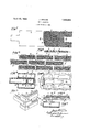
have provided a new and im- In the accompanying drawings, Fig..1 is
showing the gridthe mesh Fig. 4 is a broken plan view of the unit after the blocks have been cast and have hardened and the grid-mold has been removed.
F ig; 5 is a broken elevation of a portion of a building wall with two horizontally alined units assembled thereon.
Fig. 6 is a sectional view taken along the line 6-6 in Fi 5.
Fig. 7 is a ace view of a unit having a single blockr thereon.
Fig. Sis a perspective of one of my corner units.
Referring first to Figs. 1 to 6, inclusive, of the drawings, 1 represents the backing board of the wall covering unit, the same being preferably of composition such as is cornmonly known in the building art as wall board. rThe board is cut into proper shape, such as illustrated in Figs. 1 and 3, so that two units will interlock when secured in position in horizontal alinement and adjacent horizontal rows of blocks will present the usual staggered joints.
On the face of backing board 1 l secure a similar size and shaped sheet of metallic mesh 2. This may be as shown, a sheet of eX- panded metal or may be of woven wire or of other suitable construction.
The mesh is permanently secured to the face of lthe board 1, as by the staples 3 which are driven through the board 1 and have their ends clinched against the back of the board, as best illustrated at 4 in Fig. 2.
The board 1 with its facing of metallic mesh 2 is then laid ina horizontal position with the mesh upwardly, and the grid-mold 5-6 is placed thereon as illustrated in Fig. 3, the perimetral edges of the grid-mold matching the perimetral edges lof the board l. Suitable clamps or other means may be employed to hold the grid-mold rigidly in position on the backing board.
The grid-mold is formed by a relatively narrow perimetral wall 5 which follows and matches the perimetral contour of the board 1 and interior partitions 6 which preferably are of twice the width of the perimetral wall. These. partitions 6 are arrangedto divide the interior of the gridmold into molding cavitieseach the size and shape of the blocks which are to be cast,"and the width of the partitions is that desired for the width of the valleys or mortar spaces desired between the blocks. The reason for'making the perimetral wall 5 of the grid-mold but half the width of the partitions 6 is that the valleys or depressions to be formed about the edges of the unit are to mate with like valleys about the edges of the .adjacent units when the units are assembled on the wall, thus jointly forming the valleys or mortar spaces between the contiguous blocks of adjacent units.
The grid-mold may be made of suitablematerial. Thus it may be cast or otherwise formed of metal to provide the necessary strength and rigidity.
The cement or other material in plastic form is then lled into the mold cavities, the walls of said cavities, formed by the perimetral wall 5 and the partitions 6 vof the grid-mold, and said walls of the proper height to give the desired thickness to the blocks. A quarter or a third of an inch molddepth is usually sufficient.
The mesh 2 is embedded permanently in the block material when the latter sets and hardens, so that the block is rigidly and permanently secured to the surface of the backing board 1.
The blocks are indicated at 7 in Figs. 4 and 5. The valleys 8 between the blocks as indicated in Fig. 4 are the Width of the partitions 6 and along the perimetral edges of the unit are the half-width valleys 9 which mate with similar half-width Valleys of adjacent units, when the units are secured to the building, to form full width valleys. As will be noted the mesh is exposed in these valleys 8 and 9.
lVhen the units are secured to the building wall which is indicated at 10 in Figs. 5 and 6, nails or other fasteners 11 are driven through the mesh 2 and the backingboard 1 along the Yvalleys into the wall 10. buch fasteners are provided with relatively large head portions so as to engage and bear down on the mesh.
After the units are secured in place on the building wall the valleys 8 and 9 are iilled in or pointed with suitable mortar 12 which bonds in with the mesh 2 and covers and protects the heads of the fasteners 11.
The interlocking of the blocks of adjacent units is illustrated in Fig. 5, portions of the blocksof the next unit to the right being indicated at 7a.
In Fig. 7 I have shown a unit comprising a backing board 1a provided with a mesh 2a, and having a single block 7b formed thereon, the same being surrounded by a valley 9a which mates with like valleys on adjacent single-block units, the unit being secured to the building wall by fasteners driven through their perimetral valleys, and theV valleys being filled or pointed with mortar after the units have been secured to the building wall.
1n Fig. 8 l show a unit for forming corners of walls, the corners of window and door openings, wall ends and the like.
In such case the backing board 1b is angular to fit against two faces of the building wall and the mesh 2b is likewise angular and is stapled to the board 1.
The blocks 7c are disposed alternately as shown, each block exposing a side and an end surface.
The alternate disposal `of the blocks enables the corner members to interlock with the standard unit shown in Fig. 4.
The units may be formed with any desired number of rows of blocks and any number of blocks in a row, but the units are preferably of an area which will be convenient and light enough to handle -and put in place with convenience and dispatch. One of the marked advantages of my improved wall covering is its relative toughness, as the blocks may be relatively thin, preferably not more than a quarter inch in depth. This also reduces the cost of the materia'l. The backing board, 'which may beY any wall board of good quality need not be relatively thick, a quarter inch thickness being ample.
. The wall covering may be formed to simulate any character of laid building units,
such as brick, tile, artificial stone blocks, building stone and the like, the material of which the blocks are formed being colored or tinted to reproduce exactly the eiect desired. The valleys may likewise be pointed with any desired color and character of mortar. The mortar being bonded by the mesh will be permanently held in position.
I claim l. A wall covering unit to be fastened to a building wall and comprising a backing board having a metallic mesh secured to its face and a block of plastic material cast onto said board and having the mesh embedded therein.
2. A wall covering unit to be fastened'to a building wall and comprising a backing board having a metallic mesh secured to its face and a block of plastic material cast onto said board and having the mesh embedded therein, the edges of the board extending beyond the edges of the block to form valleys for pointing with mortarv when the unit is in place.
3. A wall covering unit to be fastened to a building wall and comprising a backingy board having a metallic mesh secured to its face and a block of plastic material cast onto said\board and having the mesh embedded therein, the edges of the board and the mesh extending beyond the edges of the block to form valleys for pointing with mortar when the unit is in place. j
4. A wall covering unit comprising a backingl boa-rd, a sheet of metallic mesh covering and secured to the face of the board, and a plurality of blocks of plastic material cast on said board and having portions of the mesh embedded in their material, the blocks beingl in spaced relation to `each other toprovide vfor intervening valleys.
5. A wall covering unit comprising a backing board, a sheet of metallic mesh covering and secured to the face of the board, and a plurality of blocks of plastic material cast on said board and having portions of the mesh embedded in their material, the blocks being in spaced relation to each other to provide for intervening valleys, and the mesh beingexposed in said valleys to form a bond for the mortar pointing.
6. A wall covering umt comprising a back- I ing board, a sheet of metallic mesh covering and secured to the face of the board, and a plurality of blocks of plastic material cast on said board and having 'portions 'of the mesh embedded in their material, the blocks being in spaced relation to each other to form intervening valleys and the blocks being also setl back from the perimetral edges of the backing board so that valleys may be formed at the contiguous edges of adjoining units when the units are fastened to a building.
7. A wall covering unit comprising a backing board, a sheet of metallic mesh covering" 'the backing board so'that valleys may formed at'the contiguous edges of adjoininfr units when the units are fastened to a build: ing, the perimetral valleys of the units being substantially half the width of the valleys between blocks on the same unit.
8. A Wall covering unit comprising a backing board, a sheet of metallic mesh covering and secured to the face of tlie board, and a plurality of blocks of plastic material cast on said board and having portions of the mesh embedded in their material, the blocks being in spaced relation to each other to form intervening valleys and the blocks bev ing also setback from the' perimetral edges of the backing board so that valleys may be formed at the contiguous edges of adjoining units when the'units are fastened to a building, the blocks in adjacent rows on the same unit being in staggered relation so that the ends of adjacent units will interlock.
9.l A Wall covering unit comprising a block of plastic materialcast on top of a sheet of metal mesh, the sheet extending beyond the sides .and ends of said block, 'and being exposed to form the interventing `valleys be tween adjacent blocks. v
10. A wall covering unit comprising a plurality of blocks cast of plastic material on top of a continuous sheet of metal mesh, the
"units being separated by valleys.
units being separated by valleys, and the l mesh being exposed in said valleys.
12. A wall covering unit comprising a continuous sheet of metal mesh on top of which are cast a plurality of blocks of plastic material, the mesh being exposed in the Valleys between the individual blocks to permit pointing with mortar.
13. A wall covering unit comprising a continuous sheet of metal mesh on top of which are cast a plurality of spaced apart blocks of plastic material, the mesh being exposed around the blocks to form valleys between the blocks of the unit and between such blocks and the blocks of adjacent units, said val leys permitting subsequent pointing with mortar.
14. A wall covering unit comprising a continuous backing board, a metal mesh permanently secured to the face of said board, and spaced apart blocks of plastic material cast onto said mesh and board.
15. A Wall covering unit comprising a continuous backing board, a metal mesh permap nently secured to the face of said board, and spaced apart blocks of plastic material cast onto said mesh and board, said mesh being a exposed between the blocks to form the valleys for pointing with mortar.
16. A wall Covering unit comprising a continuous backing board, a metal mesh permanently secured to the face of said board, and spaced apart blocks of plastic material cast- Vonto said mesh and board, said mesh being exposed' between and around the blocks to form valleys for pointin with mortar.
Si ned at Pittsburgh, Marc 1931.
JOSEPH KRAUSS.
a., this 7th day of
Priority Applications (1)
| Application Number | Priority Date | Filing Date | Title |
|---|---|---|---|
| US521083A US1853824A (en) | 1931-03-09 | 1931-03-09 | Wall covering |
Applications Claiming Priority (1)
| Application Number | Priority Date | Filing Date | Title |
|---|---|---|---|
| US521083A US1853824A (en) | 1931-03-09 | 1931-03-09 | Wall covering |
Publications (1)
| Publication Number | Publication Date |
|---|---|
| US1853824A true US1853824A (en) | 1932-04-12 |
Family
ID=24075272
Family Applications (1)
| Application Number | Title | Priority Date | Filing Date |
|---|---|---|---|
| US521083A Expired - Lifetime US1853824A (en) | 1931-03-09 | 1931-03-09 | Wall covering |
Country Status (1)
| Country | Link |
|---|---|
| US (1) | US1853824A (en) |
Cited By (20)
| Publication number | Priority date | Publication date | Assignee | Title |
|---|---|---|---|---|
| US2416554A (en) * | 1944-05-19 | 1947-02-25 | Johns Manville | Method of making siding units |
| US2807070A (en) * | 1954-08-02 | 1957-09-24 | Chester A Thomas | Apparatus for constructing prefabricated masonry walls |
| US2958903A (en) * | 1958-04-24 | 1960-11-08 | Kloeckner Humboldt Deutz Ag | Briquetting roller press |
| US3067545A (en) * | 1957-12-12 | 1962-12-11 | Richard M Gaines | Artificial siding for frame buildings |
| US3332187A (en) * | 1963-12-11 | 1967-07-25 | Brix Corp | Brick wall panel and method of making |
| US3340660A (en) * | 1963-12-11 | 1967-09-12 | Brix Corp | Brick wall panel and method of making same |
| US3426490A (en) * | 1966-12-23 | 1969-02-11 | Bric Wall Mfg Co Inc | Masonry veneer siding and mold |
| US3496694A (en) * | 1968-03-04 | 1970-02-24 | Hicks Van Pelt Joint Venture | Artificial facing method |
| US4016692A (en) * | 1972-10-20 | 1977-04-12 | F. Von Langsdorff Bauverfahren Gmbh | Composite paving structures and laying units therefor |
| US4920716A (en) * | 1988-06-09 | 1990-05-01 | Coffey Jess R | Veneer construction and method of achieving same |
| US5029424A (en) * | 1989-06-06 | 1991-07-09 | Zimmerman Stucco And Plastic, Inc. | Decorative quoin |
| US5470623A (en) * | 1991-12-11 | 1995-11-28 | Emaux De Briare Technologies, S.A. | Decorative panel having adhesively set and arbitrarily positioned polygonal mosaic elements |
| US5860259A (en) * | 1995-05-15 | 1999-01-19 | Laska; Walter A. | Masonry insulated board with integral drainage |
| US20080155921A1 (en) * | 2006-12-29 | 2008-07-03 | Wolf David H | Veneer panel |
| US20100019123A1 (en) * | 2008-07-28 | 2010-01-28 | Scott System, Inc. | Modular layout form for embedding objects in a settable material |
| US20110180452A1 (en) * | 2010-01-25 | 2011-07-28 | Mattel, Inc. | Display Assembly |
| US20130097950A1 (en) * | 2011-10-21 | 2013-04-25 | Jason Hunsaker | Fiber Enforced Thin Brick Sheet and Process |
| US9903124B2 (en) | 2008-02-06 | 2018-02-27 | Boral Stone Products Llc | Prefabricated wall panel with tongue and groove construction |
| USRE47694E1 (en) | 2012-08-08 | 2019-11-05 | Boral Stone Products Llc | Wall panel |
| US11332943B2 (en) | 2019-10-08 | 2022-05-17 | D.A. Distribution Inc. | Wall covering with adjustable spacing |
-
1931
- 1931-03-09 US US521083A patent/US1853824A/en not_active Expired - Lifetime
Cited By (32)
| Publication number | Priority date | Publication date | Assignee | Title |
|---|---|---|---|---|
| US2416554A (en) * | 1944-05-19 | 1947-02-25 | Johns Manville | Method of making siding units |
| US2807070A (en) * | 1954-08-02 | 1957-09-24 | Chester A Thomas | Apparatus for constructing prefabricated masonry walls |
| US3067545A (en) * | 1957-12-12 | 1962-12-11 | Richard M Gaines | Artificial siding for frame buildings |
| US2958903A (en) * | 1958-04-24 | 1960-11-08 | Kloeckner Humboldt Deutz Ag | Briquetting roller press |
| US3332187A (en) * | 1963-12-11 | 1967-07-25 | Brix Corp | Brick wall panel and method of making |
| US3340660A (en) * | 1963-12-11 | 1967-09-12 | Brix Corp | Brick wall panel and method of making same |
| US3426490A (en) * | 1966-12-23 | 1969-02-11 | Bric Wall Mfg Co Inc | Masonry veneer siding and mold |
| US3496694A (en) * | 1968-03-04 | 1970-02-24 | Hicks Van Pelt Joint Venture | Artificial facing method |
| US4016692A (en) * | 1972-10-20 | 1977-04-12 | F. Von Langsdorff Bauverfahren Gmbh | Composite paving structures and laying units therefor |
| US4920716A (en) * | 1988-06-09 | 1990-05-01 | Coffey Jess R | Veneer construction and method of achieving same |
| US5029424A (en) * | 1989-06-06 | 1991-07-09 | Zimmerman Stucco And Plastic, Inc. | Decorative quoin |
| US5470623A (en) * | 1991-12-11 | 1995-11-28 | Emaux De Briare Technologies, S.A. | Decorative panel having adhesively set and arbitrarily positioned polygonal mosaic elements |
| US5860259A (en) * | 1995-05-15 | 1999-01-19 | Laska; Walter A. | Masonry insulated board with integral drainage |
| US7997039B2 (en) * | 2006-12-29 | 2011-08-16 | Boral Stone Products, LLC | Veneer panel |
| US20080155921A1 (en) * | 2006-12-29 | 2008-07-03 | Wolf David H | Veneer panel |
| US10557273B2 (en) | 2008-02-06 | 2020-02-11 | Boral Stone Products Llc | Prefabricated wall panel with tongue and groove construction |
| US9903124B2 (en) | 2008-02-06 | 2018-02-27 | Boral Stone Products Llc | Prefabricated wall panel with tongue and groove construction |
| US10378216B2 (en) | 2008-02-06 | 2019-08-13 | Boral Stone Products Llc | Prefabricated wall panel with tongue and groove construction |
| US11891814B2 (en) | 2008-02-06 | 2024-02-06 | Westlake Royal Stone Llc | Prefabricated wall panel with tongue and groove construction |
| US10329775B2 (en) | 2008-02-06 | 2019-06-25 | Boral Ip Holdings (Australia) Pty Limited | Method of forming a wall panel |
| US20100019123A1 (en) * | 2008-07-28 | 2010-01-28 | Scott System, Inc. | Modular layout form for embedding objects in a settable material |
| US20110180452A1 (en) * | 2010-01-25 | 2011-07-28 | Mattel, Inc. | Display Assembly |
| US10072426B2 (en) * | 2011-10-21 | 2018-09-11 | Old Mill Brick Llc | Fiber enforced thin brick sheet and process |
| US20130097950A1 (en) * | 2011-10-21 | 2013-04-25 | Jason Hunsaker | Fiber Enforced Thin Brick Sheet and Process |
| US20190119927A1 (en) * | 2011-10-21 | 2019-04-25 | Old Mill Brick Llc | Fiber enforced thin brick sheet and process |
| US10443247B2 (en) * | 2011-10-21 | 2019-10-15 | Old Mill Brick Llc | Fiber enforced thin brick sheet and process |
| US20220282492A1 (en) * | 2011-10-21 | 2022-09-08 | Old Mill Brick Llc | Fiber enforced thin brick sheet and process |
| US11781322B2 (en) | 2011-10-21 | 2023-10-10 | Old Mill Brick Llc | Fiber enforced thin brick sheet and process |
| US20240035287A1 (en) * | 2011-10-21 | 2024-02-01 | Old Mill Brick Llc | Fiber enforced thin brick sheet and process |
| US9556619B2 (en) * | 2011-10-21 | 2017-01-31 | Old Mill Brick Incorporated | Fiber enforced thin brick sheet and process |
| USRE47694E1 (en) | 2012-08-08 | 2019-11-05 | Boral Stone Products Llc | Wall panel |
| US11332943B2 (en) | 2019-10-08 | 2022-05-17 | D.A. Distribution Inc. | Wall covering with adjustable spacing |
Similar Documents
| Publication | Publication Date | Title |
|---|---|---|
| US1853824A (en) | Wall covering | |
| US3332187A (en) | Brick wall panel and method of making | |
| US2130911A (en) | Building unit | |
| US3426490A (en) | Masonry veneer siding and mold | |
| US2852932A (en) | Tile and grouting assembly | |
| US3496694A (en) | Artificial facing method | |
| US3621625A (en) | Brick siding | |
| US5268137A (en) | Method of making an object retention liner for concrete construction | |
| US2178535A (en) | Method and apparatus for making brick-faced concrete walls | |
| US1994644A (en) | Art of building material | |
| US2305684A (en) | Method of molding building panels | |
| US2046213A (en) | Monolithic, metallic-reenforced slab | |
| US1976947A (en) | Wall veneer | |
| US5894676A (en) | Brick laying template | |
| US1886363A (en) | Wall veneer | |
| US1888417A (en) | Multiple slab unit | |
| US1147704A (en) | Imitation wall and tile construction. | |
| US1853822A (en) | Wall covering | |
| US3683579A (en) | Artificial stone facing construction and method therefor | |
| US2183450A (en) | Facing unit | |
| US2011510A (en) | Building construction | |
| US5855075A (en) | Brick-laying template | |
| US1852715A (en) | Tile or analogous simulation | |
| US1688405A (en) | Wall-veneering material | |
| US2098929A (en) | Block or slab molding means and method |