US1853815A - Coin box - Google Patents
Coin box Download PDFInfo
- Publication number
- US1853815A US1853815A US289490A US28949028A US1853815A US 1853815 A US1853815 A US 1853815A US 289490 A US289490 A US 289490A US 28949028 A US28949028 A US 28949028A US 1853815 A US1853815 A US 1853815A
- Authority
- US
- United States
- Prior art keywords
- tray
- coins
- coin
- arms
- handle
- Prior art date
- Legal status (The legal status is an assumption and is not a legal conclusion. Google has not performed a legal analysis and makes no representation as to the accuracy of the status listed.)
- Expired - Lifetime
Links
Images
Classifications
-
- A—HUMAN NECESSITIES
- A45—HAND OR TRAVELLING ARTICLES
- A45C—PURSES; LUGGAGE; HAND CARRIED BAGS
- A45C1/00—Purses; Money-bags; Wallets
- A45C1/12—Savings boxes
Definitions
- the object of this invention is to provide a new and novel coin receiving receptacle known as a fare box, which is enclosed by means of four transparent sides and having the conventional coin receiving opening at the top.
- the specific purpose of the invention is to provide a mechanism whereby the operator will have a-double visualization of the coin or coins deposited in the fare box be-' fore they finally enter the locked coin receiving compartment placed below the mechanism.
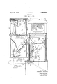
- Fig. 1 is a side elevational view thereof partly in cross-section.
- Fig. 2 is a cross-sectional plan view on the line 22 of Fig. 1, and
- Fig. 3 is a cross-sectional elevational view on the line 33 of Fig. 2.
- the locked compartment 1 is of conventional construction and receives the coins from the coin box.
- Mounted on the top of the locked compartment 1 are four standards 2 composed of angle iron which form corner posts for the glass sides 3 which are four in number, so that the coins may be seen from 1928.
- coin receiving tray 7 is rigidly secured to the arm 6 and normally closes an opening 8 in the top 9 of the locked compartment.
- a shaft 4 passes through the An arm '10 is secured to the upper face 'of tangular in cross-section and lie parallel to the standards 2.
- Each of the rear plates 13 carry side plates 15 which plates are connected by means of a top plate 16 and a front plate 17 which is arcuate in shape as clearly shown in Fig. 3.
- a coin receiving tray having a bottom wall 21 and sidewalls 22.
- This coin receiving tray is pivoted on the arms 10 by means of pins 23 which extend through lugs 24.
- the front plates 13 have brackets 25 secured thereto which are provided with pins 26 which support the top coin receiving tray 27 which consists of a front wall 28, a bottom wall 29 and sidewalls 30.
- the bottom wall 29 is provided'with rearwardly extending fingers 31 which engage beneath shoulders 32 of the top wall 16 heretofore described.
- the arms 10 normally engage the fingers 31 and hold the top tray 27 in the position shown in full lines in Fig. 1.
- a conventional cap 33 On top of the standards 2 is mounted a conventional cap 33 having a coin hopper 34.
- the coin or coins are deposited in the opening in the cap 33 and readily pass through the coin hopper 34 onto the bottom wall 29 of the top tray 27. If any of the coins should strike the top plate 16 they would be deflected into the. tray 27 where they remain until the operator raises the handle 5. As the coins rest in the top tray they can be readily seen by looking through any one of the four glass sides 3. When the operator raises the handle 5 he moves the various parts into the dotted line position shown in Fig. 1, the arms 10 moving forwardly so that the top tray 27 drops by gravity and the bottom wall 21 of the second tray moves forwardly and upwardly to the position shown in Fig. 3 so that the coins pass from the top tray into the second tray and now repose on the bottom wall 21 where again they may be seen from any position.
- an operating handle a tray operatively secured thereto, arms carried by said tray, a second tray having a fixed pivot at one end thereof and having its other end supported by said arms, said arms being removed from supporting said second tray in elevated position when'said handle is raised so as to permit said second tray to fall by gravity and to drop the coins deposited therein.
- a handle normally positioned in a substantially horizontal plane, upstanding arms connected to said handle and a tray pivoted at one end to a fixed support and normally supported at its other end by said arms, said arms sliding toward said pivoted end when said handle is raised and permitting said tray to fall by gravity so as to drop the coins deposited therein.
- a handle normally positioned in a substantially horizontal plane, upstanding arms connected to said handle, a tray pivoted at one end to a fixed support and normally supported at its other end by said arms, said arms sliding toward said pivoted end when said handle is raised and permitting said tray to fall by gravity so as to drop the coins deposited therein, and means to prevent the coins leaving said tray until tne tray has been lowered to a predetermined extent.
- an operating handle operatively connected to said operating handle, a tray pivoted to said arms, fixed guides, and pins carried by said tray and extending into said guides so as to cause said tray to be tilted upwardly when said handle is raised and to be lowered when said handle is lowered.
- an upper, lower and metal tray an operating handle, said lower tray being operatively connected to said operating handle so as to move in unison therewith, arms carried by said lower tray, said metal tray being operatively connected to and supported by said arms, fixed guides, and pins carried by said last men tioned tray extending into said guides, the upper tray being pivotally mounted at one end and supported at its other end by said arms.
Description
April 12, 1932. K. JACKSON COIN BOX //v vE/v TOR. KENNETH JACKSON.
ATTORNEY Filed June 30, 1928 Patented Apr. 12, 1932 '9 UNITED STATES PATENT OFFICE KENNETH JACKSON, OF ST. ALBANS, NEW YORK, ASSIGNOB T0 OHMER FARE REGISTER COMPANY, OF DAYTON, OHIO com ox Application filed'June 30,
The object of this invention is to provide a new and novel coin receiving receptacle known as a fare box, which is enclosed by means of four transparent sides and having the conventional coin receiving opening at the top. The specific purpose of the invention is to provide a mechanism whereby the operator will have a-double visualization of the coin or coins deposited in the fare box be-' fore they finally enter the locked coin receiving compartment placed below the mechanism.
Frequently, the coins deposited in devices heretofore known were subject to dispute. In rush periods the coins may be deposited so rapidly that the operator cannot distinguish what coins were last deposited. In my improved construction I have provided a plurality of coin receiving trays so that the operator can cause the coins to successively pass from one tray to the next and is thereby enabled to visualize what coins have been deposited.
In devices heretofore known there has been only one coin receiving tray and when the operator tilted that tray the coin passed directly into the locked box where the coin could not be seen. Disputes sometimes arose as to what coin or coins were deposited. In my improved construction the coin does not directly pass into the locked department but passes to another tray where it can be seen and disputes are thereby avoided.
With these and other objects in view I have shown my invention by way of illustration in the attached drawings forming a part of this specification in which Fig. 1 is a side elevational view thereof partly in cross-section.
Fig. 2 is a cross-sectional plan view on the line 22 of Fig. 1, and
Fig. 3 is a cross-sectional elevational view on the line 33 of Fig. 2.
The locked compartment 1 is of conventional construction and receives the coins from the coin box. Mounted on the top of the locked compartment 1 are four standards 2 composed of angle iron which form corner posts for the glass sides 3 which are four in number, so that the coins may be seen from 1928. Serial No. 289,490.
every side. two opposite sides of the locked compartment 1, which shaft isprovided with an operating handle 5 and with an arm 6 extending in an opposite direction from the handle 5. coin receiving tray 7 is rigidly secured to the arm 6 and normally closes an opening 8 in the top 9 of the locked compartment.
A shaft 4 passes through the An arm '10 is secured to the upper face 'of tangular in cross-section and lie parallel to the standards 2. Each of the rear plates 13 carry side plates 15 which plates are connected by means of a top plate 16 and a front plate 17 which is arcuate in shape as clearly shown in Fig. 3. Each of :the side. plates 15- c.
are provided with slots '18 which receive pins 19, which pins are carried by the upper end of the rear wall 20 of a coin receiving tray having a bottom wall 21 and sidewalls 22. This coin receiving tray is pivoted on the arms 10 by means of pins 23 which extend through lugs 24.
The front plates 13 have brackets 25 secured thereto which are provided with pins 26 which support the top coin receiving tray 27 which consists of a front wall 28, a bottom wall 29 and sidewalls 30. The bottom wall 29 is provided'with rearwardly extending fingers 31 which engage beneath shoulders 32 of the top wall 16 heretofore described. The arms 10 normally engage the fingers 31 and hold the top tray 27 in the position shown in full lines in Fig. 1.
On top of the standards 2 is mounted a conventional cap 33 having a coin hopper 34.
In operation the coin or coins are deposited in the opening in the cap 33 and readily pass through the coin hopper 34 onto the bottom wall 29 of the top tray 27. If any of the coins should strike the top plate 16 they would be deflected into the. tray 27 where they remain until the operator raises the handle 5. As the coins rest in the top tray they can be readily seen by looking through any one of the four glass sides 3. When the operator raises the handle 5 he moves the various parts into the dotted line position shown in Fig. 1, the arms 10 moving forwardly so that the top tray 27 drops by gravity and the bottom wall 21 of the second tray moves forwardly and upwardly to the position shown in Fig. 3 so that the coins pass from the top tray into the second tray and now repose on the bottom wall 21 where again they may be seen from any position. The arcuate plate 17. Such a construction will prevent the coins overshooting the second tray and will insure that they are deposited therein. When the operator releases the handle 5 the parts resume their positions shown in full lines in Fig. 1 because the operating handle 5 is considerably heavier than the coin tray 7, arms 10 and parts associated therewith. During this movement of the parts the pins 23 move rearwardly so as to lower the bottom wall 21 of the metal tray and deposit the coins on the coin tray 7 where again they may be inspected. When the operator again raises the operating handle 5 the bottom tray 7 will drop to its dotted line position and the coins resting thereon will be deposited in the locked compartment 1.
It is obvious that by the use of the construction shown herein the coins will be visually displayed three times and that the operator must raise the handle 5 twice in order to pass the coins from the top tray into the locked compartment.
While I have shown the preferred construction of my invention I fully realize that many changes may be made in the specific embodiment thereof and I, therefore, do not desire to limit myself to the specific construction shown herein except as I may limit myself in the annexed claims: 7
1. In a coin receiving box, an operating handle, a tray operatively secured thereto, arms carried by said tray, a second tray having a fixed pivot at one end thereof and having its other end supported by said arms, said arms being removed from supporting said second tray in elevated position when'said handle is raised so as to permit said second tray to fall by gravity and to drop the coins deposited therein.
2. In a coin receiving box, a handle normally positioned in a substantially horizontal plane, upstanding arms connected to said handle and a tray pivoted at one end to a fixed support and normally supported at its other end by said arms, said arms sliding toward said pivoted end when said handle is raised and permitting said tray to fall by gravity so as to drop the coins deposited therein.
3. In a coin receiving box, a handle normally positioned in a substantially horizontal plane, upstanding arms connected to said handle, a tray pivoted at one end to a fixed support and normally supported at its other end by said arms, said arms sliding toward said pivoted end when said handle is raised and permitting said tray to fall by gravity so as to drop the coins deposited therein, and means to prevent the coins leaving said tray until tne tray has been lowered to a predetermined extent.
1. In a coin receivingbox, an operating handle, arms operatively connected to said operating handle, a tray pivoted to said arms, fixed guides, and pins carried by said tray and extending into said guides so as to cause said tray to be tilted upwardly when said handle is raised and to be lowered when said handle is lowered.
5. In a coin receiving box, an upper, lower and metal tray, an operating handle, said lower tray being operatively connected to said operating handle so as to move in unison therewith, arms carried by said lower tray, said metal tray being operatively connected to and supported by said arms, fixed guides, and pins carried by said last men tioned tray extending into said guides, the upper tray being pivotally mounted at one end and supported at its other end by said arms.
In testimony whereof I aflix my signature.
KENNETH JACKSON.
Priority Applications (1)
| Application Number | Priority Date | Filing Date | Title |
|---|---|---|---|
| US289490A US1853815A (en) | 1928-06-30 | 1928-06-30 | Coin box |
Applications Claiming Priority (1)
| Application Number | Priority Date | Filing Date | Title |
|---|---|---|---|
| US289490A US1853815A (en) | 1928-06-30 | 1928-06-30 | Coin box |
Publications (1)
| Publication Number | Publication Date |
|---|---|
| US1853815A true US1853815A (en) | 1932-04-12 |
Family
ID=23111762
Family Applications (1)
| Application Number | Title | Priority Date | Filing Date |
|---|---|---|---|
| US289490A Expired - Lifetime US1853815A (en) | 1928-06-30 | 1928-06-30 | Coin box |
Country Status (1)
| Country | Link |
|---|---|
| US (1) | US1853815A (en) |
Cited By (3)
| Publication number | Priority date | Publication date | Assignee | Title |
|---|---|---|---|---|
| US2835439A (en) * | 1955-03-15 | 1958-05-20 | Max L Grant | Multiple throw coin receiver |
| US2869776A (en) * | 1959-01-20 | Throughway fare collection device | ||
| US4240437A (en) * | 1978-07-31 | 1980-12-23 | Church Charles J | Electric massage apparatus and method |
-
1928
- 1928-06-30 US US289490A patent/US1853815A/en not_active Expired - Lifetime
Cited By (3)
| Publication number | Priority date | Publication date | Assignee | Title |
|---|---|---|---|---|
| US2869776A (en) * | 1959-01-20 | Throughway fare collection device | ||
| US2835439A (en) * | 1955-03-15 | 1958-05-20 | Max L Grant | Multiple throw coin receiver |
| US4240437A (en) * | 1978-07-31 | 1980-12-23 | Church Charles J | Electric massage apparatus and method |
Similar Documents
| Publication | Publication Date | Title |
|---|---|---|
| US1853815A (en) | Coin box | |
| US1778187A (en) | Vending machine | |
| US1849145A (en) | Vending or serving machine | |
| US2197633A (en) | Dispensing machine | |
| US1939127A (en) | Vending machine | |
| US2128179A (en) | Dispensing machine | |
| US2079255A (en) | Coin and ticket receptacle | |
| US2088856A (en) | Vending apparatus | |
| US1801308A (en) | Game apparatus | |
| US3301479A (en) | Cash register drawer construction | |
| US1444863A (en) | Vending machine | |
| US1841652A (en) | Record and index card system | |
| US1418770A (en) | Register | |
| US2278237A (en) | Counting device | |
| US1731829A (en) | Coin-opebated vending machine | |
| US1732422A (en) | Vending machine | |
| US1126977A (en) | Stand for sorting mail-matter. | |
| US1934403A (en) | Coin control and selecting mechanism | |
| US1555955A (en) | Sandwich-vending machine | |
| US1986771A (en) | Coin register | |
| US1565213A (en) | Coin-controlled vending machine | |
| US1831893A (en) | Release for vending merchandise | |
| USRE21096E (en) | Cashier machine | |
| US1820343A (en) | Change making machine | |
| US1982119A (en) | Amusement machine |