US1853774A - Paper manufacture - Google Patents
Paper manufacture Download PDFInfo
- Publication number
- US1853774A US1853774A US408564A US40856429A US1853774A US 1853774 A US1853774 A US 1853774A US 408564 A US408564 A US 408564A US 40856429 A US40856429 A US 40856429A US 1853774 A US1853774 A US 1853774A
- Authority
- US
- United States
- Prior art keywords
- boiler
- paper
- stock
- fibers
- separator
- Prior art date
- Legal status (The legal status is an assumption and is not a legal conclusion. Google has not performed a legal analysis and makes no representation as to the accuracy of the status listed.)
- Expired - Lifetime
Links
Images


Classifications
-
- D—TEXTILES; PAPER
- D21—PAPER-MAKING; PRODUCTION OF CELLULOSE
- D21B—FIBROUS RAW MATERIALS OR THEIR MECHANICAL TREATMENT
- D21B1/00—Fibrous raw materials or their mechanical treatment
- D21B1/04—Fibrous raw materials or their mechanical treatment by dividing raw materials into small particles, e.g. fibres
- D21B1/12—Fibrous raw materials or their mechanical treatment by dividing raw materials into small particles, e.g. fibres by wet methods, by the use of steam
Definitions
- This invention relates generally to the manufacture of paper, and. has-particular reference to a new quality of material of the facture and which is, by my further invention. 1.
- An incidental object of my invention is further to provide a method of paper manu- 5 facture generally, whichcan be carried on at a very low plant operating expense, and with a substantially minimum outlayfor manufacturing equipment. It may bementioned particularly that in the item of power I am, by my invention, enabled to effect a-saving of substantially onehalf.
- Another object of the-invention is to produce a paper which will have great. strength. This is achieved mainly by the factor of utilizing the fiber in substantial lengths, andby that of preserving it in a substantially unweakened condition as it is produced in na-.
- the former factor is attained by elimmating the grinding or equivalent C0111", minuting process usually employed in paper manufacture, and the latter factor is attained by the elimination in the process of manufacture of the use of-chemicals that .impair the natural strength of the fiber.
- Another object is to provide a novel combin ation of mechahismsand interconnections by means of intercommunication between them which is adaptedto carryout-my inven tion in respect to the novel method and the novel product obtainable thereby at a relatively high production rate and at a substantiallyiminimum cost, compared With any other known method of papermanufactureh
- Other objectsand advantages will be apparent to-one skilled in. the art fronithe de-' scription hereinafter ;gi-ven,.and from an eX-' aminationof thedrawings, which accompany and form'a part of thisspecification. What constitutes my invention will be provided forits reception.
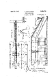
- FIG. 1 is a plan view showing in somewhat diagrammatic form the relation-of chipping, screening,'- and boiling portions of the apparatus; l
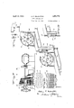
- Figure II shows the stock tanks for the; softened material'and some of the devices subsequently called into-ac- Figures III and.
- T f 5 i Figures 'V' and VI are, respectively; side and end views of the chip screening :appara" tus.
- Figures IX, X, and XI show details of the devices for distributing the softened material among the storage tanks 1
- Figure XII is a section on the line XII XII of Figure II,-and shows among other things the fiber'separating machines.
- Figure' XIII is a section of the mechanism shown'in Figure XII, taken on the line XIIIXIII of-said figure. 1 a
- Figures XIV, XV; XVI, XVII, and XVIII collectively show the construction of the fiber separating machines.
- Figure XIX is aside elevation, partly in' section, of a screen mechanism for reception
- Figure XXII is a side elevation partlyin section of a rod mill employed as a preferred form of apparatus for homogenizing thethe; strength, of: the fiber.
- Figure XXIII is an end view, partially in section, of the subject matter of Figure XXII.
- Figure XXIV is a side elevation, partly in section, of a barking machine of the type preferred for removing the bark from wood preparatory to its being subjected to the chipping operation indicated, for example, in Figures II and IV.
- Figure XXV is an elevation of the intake end of the machine shown in Figure XXIV.
- Figure XXVI is a section on the line XXVI-XXVI of Figure XXIV.
- the present invention includes means for utilizing for paper manufacture fiber isolated from a suitable fibrous raw. material such as wood, for exa'mple,yby aprocess of softeningthe fibrous material whereby separation of the fiber from the remaining constituent elements of the wood or, like substances is effected substantially without weakening or impairment of process consists mainly in boiling wood or the like, in such a manner and preferably in a weak: solution ofsoda ash orthe like, so as: to; effectthe' separation of the fibers by dissolving out. of: the the; wood the resins or other substances which bind them togetherin; the natural; state.
- This softening operation is carried on, preferably,,in. a rotary boiler and in the presence of live steam, and;
- my invention by using about one and one half pounds of soda ash for each cubic foot of the wood materialtobe treated, although the amount. of soda ash, if used,,may be varied
- the boiler is then closed as by-- a manhole cover provided for the purpose, androtation of the boiler is started so as to agitate, as by tumbling, the contents therein.
- The'boiler maybe run dry-for a short'preliminary period tocause a thorough Such softening commingling of its solid contents, after which steam may be turned into it, or the setting of the boiler into motion and the admission of the steam into it may be simultaneous.
- soda ash per cubic foot of material to be treated that is, one and one-half pounds per cubic foot, will give a solution in the.
- Baum will be 1 or'possibly less- Even if tomary in other processes, the great volume of water. preventing the scorching o-r charring of the material, which has, in part, been one obstacle in. the way of shortening cooking operations in other processes by increase of temperature.
- the steam is preferably introducedinto'the boiler near the center thereof or onkan axial line, and is thence distributed by branch; pipes soastoaid or supplement the rotary movementof' the boiler in operation for eifectinga thorough agitation and uniform heatingof the contents of the boiler.
- a This part ofthe apparatus consists, preferably, of an unlined globular iron shell .rotatably mounted on trunnions 21 and 22, disposed co-.
- the steam is admitted 7 through a steam supply pipe 27 extending axially through: one of the supportingtrunnions for the boiler on oneside thereof, a bleeder pipe 28 extending outwardly through the trunnion at the opposite side.
- the pipes 21" and 28 are bolted'togetherend to end by aid of terminal flanges 29 and 30 between which isinterposeda division plate 31 which intercepts communication between them.
- the shell 20 revolves on its trunnions about the fixed pipes27and28-as an axis.
- the admission of steam to theboiler is controlled as by the usual valve 32, and th'e bleeder is equipped with the usualautomatic trap, not illustrated.
- a hand-operated valve 35 and pipe are preferably employed, the valve being so placed and constructed that it may he operated,when the softening operation iscompleted, to relieve the boilerfrom the larger part of its internal pressure 1. and of-much'of the liquid contents.
- a blowoff pipe Disposed at the side of the boiler preferably diametrically oppositethe manhole is, a blowoff pipe having a'valve 36 and which is adapted to be connected by a suitable-union 38 to.
- a drain pipe or hose 39 leading to a sewer or other dischargepoint leading to a sewer or other dischargepoint.
- the interior of the boiler around the outlet tothe blow-oil pipe is provided preferably with a. perforated plate or screen 40 of sufiicie-nt fineness as a means to retain in the boiler substantially all of the useful materialrwhile. allowing the waste liquor to pass without material interference with drainage. his construction is much. cheaper and simpler than the usual blow-pit used in pulp-making operations, and
- the remain ing contents remaining in the boiler may be washed, as vloy meansof an ordinary hose or the likeinserted-through the manhole of the boiler, until all of the refuse liquor and its contents are washedout, such washing also removing substantially all of the remaining results, in itself. in a substantial reduction indissolved and soluble matter notcarried off with theliquor in drainage; This washing operation in the boiler consumes only a few minutes, and may, under certain conditions,
- This screw conveyor carries the previously treated .material from the receptacle 41 to a conveyor 43 .( Figures 11, IX, and X)' thatfis prefer-- ably a chain conveyor compr1sing cross-bars 44gof th'e usual type," and operating onan incline as shownin Figure. X.
- thebars 44- pass above and in close] contact with a screen 45' which is of comparatively fine'mesh.
- awasher for example, a set-of shower pipes 46 which thoroughly sprinkle and wash the material as it is carried up over the said screen 45, the
- the material carried by the conveyor 43 is distributed equally among the aforesaid equalization tanks, this distribution being maintained until the said tanks are filled to the desired extent.
- the tanks of whatsoever number, are collectively'of sufficient ca pacity to receive a number of batches of treat-- its ing a substantially uniform consistency of V the'contents, regardless of slight immaterial variations of results incidental to said treatments.
- a duplicate set of tanks and associated elements may .be placed as shown in FigureIX, at the'other side of the conveyor 43 from thetanks 50, 51, and 52.
- exam le aree ui )ed res ectivel Y with a i-- t'ators 58, which are preferably rotary, driven by anys'uitable connections, as by gearing and shafts shown, and which are connected to-amotor, notillustrated, or other suitable source of driving power.
- i-- t'ators 58 which are preferably rotary, driven by anys'uitable connections, as by gearing and shafts shown, and which are connected to-amotor, notillustrated, or other suitable source of driving power.
- Each of'the said tanks is connected to a water supply.
- the water used in the tanks is conden- 1 sation water from the paper machine driers s of similar i'nachines.
- a centrifugal stock pump 61 connected to a header'62, the header in turn being connected by valve-controlled pipes 63 to the different equalization tanks, so that the pump 61 may conveniently be connected to any tank desiredl
- the pump 61 is also connected as by a suitable pipe 65 to an elevated-flow box 66, Figures XII and XIII, containing three compartmentst'z', 68, 69, Figure XXI.
- the compartment 69 is designed to receive overflow from the comp;
- I 7 may be used.
- the stock in suspension leaving through the outlet 72 enters a spread box 76 serving to spread th low of the stock to form a flat sheet con'fo iing in width'to the'throat or 77 of a fiber separator 78, first or upper one of'a' series
- the flow to the spread nd regulated by a suitle regulatin gate 71.
- the separator. 78. resembles in. a great many respects the swing, hammer machines; used; fOrIpulveriZing;oresand clays, and, to av lim itedextent, certain vegetable growths,.such as kelp and sugar cane.
- Such prior machines which have been used. forpulverizihg. purposes are, h0wever,.unsuit'able forthe present purpose, and c'ertain'changes in them are re' quired't'o be made in order to securethedesired efiect upon the material passing: through. the machine.
- the separator or machine 78x employed' in the present instance comprises a rotor 81, Figures XIV and XV, consisting. of a mum-- leer of d ks'supporting crossbarsor: rods 82, upon which rods are loosely pivoted iron plates or' centrifugal hammers 83;
- the throat or intake opening-'77: of 'themachine 78 opens into a hopper provided with bars 8% which are adjustable to cooperate with the ends of the plates 83 whenthe rotor'81 is turning. in the directionof'the arrow: The best results, for present purposes, are ob tained when the bars 84 are so adjusted as; to leave an'appreciable gap between. the ends of the plat-esand'the bars;
- the plates 83 usually were constructed from stock of'an inch thick, but in the present machine these plates are of an inch thick,1.and i approxi mately twice as many oflthe lighter and thinner plates are used as were used in the older A construction, the lighter and thinner plates being held apart on their pivots as by spacers between them.
- the presentmachines have a bottomplate85 witlrasmooth concave surface substantiallycoaxial" with the axis 86 of the rotor 81.
- the plate 85in the separator is provided with numerous circular perforations 87, Figure XVII, which arepreferably of an inch in diameter, although the size ofthe perforations may be slightly increased or decreased according to the result desired.
- the fiber separators For separation of the average lengthsof wood fiber, the fiber separators, say four in number, operate consecutively'upon the material, and means are provided for directing the flow from one 'separator'to the next until the separating operation is completed.
- This directing means is, however, so constructed that by opening a suitable by-pass, one or more of the separators may be cut out, if the full complement thereof is unnecessary to the attainment of the degree, of separation desired.
- means are also I preferably provided for regulating the water content of the flow, a change in the .water contenteffecting a changein the results produced in each machine.
- the progress of the material through any one of the separators may be sped up -or retarded by regulating the amount of water, a decrease in the amount of water causing a longer .dwellanda greater degree of fiber separation, and an increase inthe water supply resulting in a lesserdegree of separation and a coarser condition of the fiber.
- V The regulation of the water content also gives a flex'is, bility in the operationof the separators,
- the separator 88' is provided with asimilar slide or trough 94 leading to the separator 9 1,and the separator 91 in turn has a trough or slide 90 leading to the final separator .92.
- a dam 89 Located near the lower end of each ofthe slides or troughs (90, 94, 95,), is a dam 89 which may be opened to admit or: lowered to prevent the flow from the preceding separator tothe next one.
- valve 104 each equipped with a valve 104. Normally, the valves 10% are closed, and after the spaces under the screens havefilledup with waterfthe further flow is directed into the separators. Whenever it is desired toremove a part of the water before the flow enters the next separator, the valve in the corresponding outlet 101, 102, or 103, is set to allow all or any desiredpartof the water content to escape intoa trough leading to the returnwater tank 106. ,In addition to the outlets 101, 102, and 103, for allowing consequent speeding of the action in that V particular machine,- Only one of the pipes 107 .is shown inthe drawings, but it shouldbe understood that each separator has the same water supply arrangement for the'purpose stated. 7 The flow of materialleavingthe final separator, or the last onein operation if one or more of the separators has-been-cut out,
- Thetanks'areall connected to a header 118 equipped with'a separate valve 119, whereby the tanks may be independently connected to and disconnected from the header.
- the header is connected-to a stock pump of suitable construction and capacity for carrying the stock to a regulating box like-the flow box shown in Figure XXI, but located above the rod mill shown, for example, in Figure l v Said regulating box suppliesst-ock in the required regulated amount-to the rod mill, the excess stock in theregulating box being automatically returned to stock tank.
- the apparatus and process as so far de scribed can be used in producing the fibrous stock and the finished paper from any of the softer woods. It is, however, preferable :to use what maybe termed the long-fiber woods, particularly satisfactory results having been obtained from sugar and white 'pines, and from fir. Fir is particularly suitable for the purpose, and a percentage of fir included'wi'th other woods increases the desirable qualities of the finished product.
- the stock material may be reduced to pieces of a suitable size for the subsequent operations in any suitable way.
- a conveyor system such, for example, as is designated generally as 131 in Fig Iure 1, conveys the raw material to a point abovethe hopper 1 32 ofa chipper
- This chipper is preferably of the disk type, with knives 134' which are adjustable to regulate the sizeor" the chips.
- the process as a whole is facilitated by keepingall of the chips under a mar-1i mum thickness of one inch and a length or" approximately two inches. The precise length isnot of importance;-but the maximum length indicated is preferred,because it has been found to be the best one for satisfactory softening and fiberizinn.
- a bin 140 After passing through the chipper the chips fall into a bin 140, preferably having sides and bottom directing the chips to a belt-conveyor 141.
- the conveyor is inclined upward to elevate the chips to a hopper or chute 142 leading into the interior of a rotary chip screen 144, Figures I and V.
- This screen may consist of two tubular screens-145 and 1&6, one within the other, the inner screen beingof any predetermined mesh which will screen .out from .the chipped material any Part which is too coarse or too long for use tothe best advantage.
- Tithe outer screen 145 the wood is effectually decorticated,-and-the bark and other objectionable waste substance is separated from thefibrous or decorticated is of a finer mesh :thanlthe inner screen, and may @be employed,"-if desired, to screen lout dusta-nd particles which are toov small toserve a useful purpose in-thefinal product.
- the screen 144-,asshown, is on an inclined axis, and when the screened material eventually reaches the lower end of 1t, the re1eets leave the inner screen and may be earned by a suitable conveyor (not shown) to a rechipper or crusher, or disposed of in any desired way.
- the material leaving the lower end of the outer screen drops upon a'beltconveyor 1417 which runs to a chip-bin conveniently located above the boiler hereinbefore described, from which bin the chipped material is removed for use in charging said boiler.
- raw material or wood wrththe bark on it that is to be fiberized isfirst supplied in the formof billets of suitable or convenient dimensions to the barking-machine illustrated, byway of example, in Figures XXIV, XXV, and XXVI.
- he decorticated billets are then removed from the barking -machine and by any suitable and preferred means of conveyance fed into a suitable mach-me for reducing the hi1- lets to small blocks or particles of substanthe chip screening apparatus shown, for ex.-
- the softened mate rial is, as by mechanism illustrated in Figures IX, X, and XI, and specified in detail with reference thereto, conveyed to and distributed into the selected one of the various equalization tanks 50, 51, and 52, for example, where the material is, by the addition of water, converted into a suspension substantially of the consistency hereinbefore specified;
- the material in suspension is conveyed, as by the pumpfil and pipe 65, to the flow box 66, substantially in the manner hereinbefore specified with reference to Figures XII and XIII.
- the stock in suspension is passed from the fiber separators to the intake 148 of the rod mill wherein, by repeated operations, it is fin ally fiberized and the fibers are afterwards filamented into lengths of substantially admeasured standard, the fibers are separated into filaments of substantially uniform lengths suitable for forming and converting it into paper, substantially in the manner and by the means specified.
- the rod mill is preferably of the type illustrated in Figures XXII and XXIII, and which is so well known as not to require description in detail. It is deemed suificient to specify that it embodies in a rotative case 149 having a plurality of separate rod compartments 150, a complement in each compartment of alined metal rods 151. In consequence of the rotation of the case 149, a rolling and beating action of the rods within the several compartments upon the fibers fed into the mill ensues with the efiect upon them of complete filamentation.
- the case is surrounded by two cylindrical screens 152 and 153 having meshes of different degrees of fineness which serve to separate out of the mass, fibers of such fineness as will pass the outside screen 153 and discharge said fibers from the mill into a sluice-way 155. Fibers which are too coarse to pass the screen 153 are automatically returned into the compartments'150 and are there subjected to repetition of the action of the rods 151 upon them, until they are ultimately reduced thereby to such degree of fineness as to pass the screen 153.
- the stock or fibers in suspension goes, by any suitable means of conveyance, to the screen shown in Figures XIX and XX, which serves to screen out all fibers of excessive lengths and render them ready for final conversion of 1 them into paper by the operation of the paper makingmachine already indicated at A as supplying the final step of my process.
- the new and improved method ofmaking paper which consists in first reducing long fiber wood to a suitable size by passing it through a chipper and maintaining the chips in a predetermined size, conveying the chips through a chip screen conducting the treated chips to a boiler and subjecting them to a softening operation, selectively conducting the chip material to equalizing tanks where the material is by the addition-of water maintained insuspension, conveyingthe material under pressure to a flow box, then to a fiber separator, and conducting the material in suspension from the fiber separator to a reducing mill where the fibers are sep arated into filaments of substantially uniform lengths for forming and converting into paper.
- the new and improved method of making paper which consists in conducting the raw material or wood with the bark on it in the form of billets to a barking machine so as to efi'ectively decorticate the waste substance from the raw material, reducing the decorticated billets or chips to substantially uniform dimensions, conducting the chips through a screening apparatus to a boiler so asto subject the same to a softening operation, passing the soft material through equalizing tanks where the material by the addition of water is maintained in suspension, forcing the material under pressure to a flow box, passing the material in suspensionifrom the fiow box to a fiber separator where it is partially fiberized and separated, conducting the material in suspension from the fiber separator to a reducing mill where the material is finely fiberized and the fibers filamentcd into substantially admeasured standard lengths, and converting the fibers so pro 'duced into paper.
Description
April 1 2, 1932 A. E. MILLINGTON 1,853,774
PAPER MANUFACTURE Filed Nov. 20, 1929 '12 Sheets-Sheet 1 A. E. MILLII\4IGTON 1,853,774
PAPER MANUFACTURE April 12, 1932.
Filed Nov 20, 1929 12 Sheets-Sheet 2 gwwnto'c;
W GWQ April 12, 1932. A. E. MILLINGTON PAPER MANUFAC TUBE Filed Nov. 20, 1929 12 Sheets-Sheet 3 1 E WH April 12, 1932. A. E. MILLINGTON 4 V PAPER MANUFACTURE Filed Nov. 20, 1929 12 Sheets-Sheet 4 gvvuzntoz PAPER MANUFACTURE Filed Nov. 20, 1929 12 Sheets-Sheet 5 April 12, 1932. A. E. MILLINGTON 1,853,774
PAPER MANUFACTURE Filed Nov. 20, 1929 12 Sheets-Sheet 6 gwuentoc;
April 12, 1932.- A. E. MILLINGTON 1,8
PAPER MANUFACTURE Filed Nov. 20, 1929 12 Sheets-Sheet 7 A. E. MILLINGTON April 12, 1932.
PAPER MANUFACTURE Filed Nov. 20 '1929 12 Sheets-Sheet 8 April 12, 1932.
A. E. MILLINGTON PAPER MANUFACTURE Filed Nov. 20, 1929 12 Sheets-Sheet 9 OOOOOOOO OOOOOOOOO April 12, N N PAPER MANUFACTURE Filed Nov. 20, 1929 12 Sheets-Sheet l0 wag-am gn uentoo W W W W att c-401 s April 1 2, 1932'. A. E. MILLINGTON PAPER MANUFAG TUBE Filed Nov. 20, 1929 12 Sheets-Sheet' l1 April 1932. A. E. MILLINGTON PAPER MANUFAC TURE Filed Nov. 20, 1929 12 Sheets-Sheet l2 Patented Apr. 12, 1932 rema n naimrncrnrin Application filed November 20,1929. Serial No.'408,5 64..
This invention relates generally to the manufacture of paper, and. has-particular reference to a new quality of material of the facture and which is, by my further invention. 1.
tion, convertible into paper stock;
An incidental object of my invention is further to provide a method of paper manu- 5 facture generally, whichcan be carried on at a very low plant operating expense, and with a substantially minimum outlayfor manufacturing equipment. It may bementioned particularly that in the item of power I am, by my invention, enabled to effect a-saving of substantially onehalf.
Another object of the-invention is to produce a paper which will have great. strength. This is achieved mainly by the factor of utilizing the fiber in substantial lengths, andby that of preserving it in a substantially unweakened condition as it is produced in na-.
ture; The former factor is attained by elimmating the grinding or equivalent C0111", minuting process usually employed in paper manufacture, and the latter factor is attained by the elimination in the process of manufacture of the use of-chemicals that .impair the natural strength of the fiber.
Another object is to provide a novel combin ation of mechahismsand interconnections by means of intercommunication between them which is adaptedto carryout-my inven tion in respect to the novel method and the novel product obtainable thereby at a relatively high production rate and at a substantiallyiminimum cost, compared With any other known method of papermanufactureh Other objectsand advantages will be apparent to-one skilled in. the art fronithe de-' scription hereinafter ;gi-ven,.and from an eX-' aminationof thedrawings, which accompany and form'a part of thisspecification. What constitutes my invention will be provided forits reception.
hereinafter described in detail and succinctly defined in the appended claims.
In the accompanyinbg drawings, V Figure I is a plan view showing in somewhat diagrammatic form the relation-of chipping, screening,'- and boiling portions of the apparatus; l
Figure II'sa continuation of Figure I, partially broken away, a-nd' shows the stock tanks for the; softened material'and some of the devices subsequently called into-ac- Figures III and. I'Viare 'viewstaken, re-" spectively, from difierentangles, of the chipperjand'l'some of the mechanismas'sociated therewith. T f 5 i Figures 'V' and VI are, respectively; side and end views of the chip screening :appara" tus. I 1
Figures VII and VIII I are, respectively,
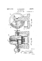
' a ,partialfron't elevation partly in section ofthe boiler, and anend elevation of gearing suitable for driving'it i t Figures IX, X, and XI, respectively, show details of the devices for distributing the softened material among the storage tanks 1 Figure XII is a section on the line XII XII of Figure II,-and shows among other things the fiber'separating machines.
Figure' XIII is a section of the mechanism shown'in Figure XII, taken on the line XIIIXIII of-said figure. 1 a
Figures XIV, XV; XVI, XVII, and XVIII collectively show the construction of the fiber separating machines.
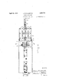
Figure XIX is aside elevation, partly in' section, of a screen mechanism for reception Figure XXII is a side elevation partlyin section of a rod mill employed as a preferred form of apparatus for homogenizing thethe; strength, of: the fiber.
softened fibers utilized in my present method of paper manufacture.
Figure XXIII is an end view, partially in section, of the subject matter of Figure XXII.
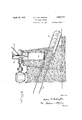
Figure XXIV is a side elevation, partly in section, of a barking machine of the type preferred for removing the bark from wood preparatory to its being subjected to the chipping operation indicated, for example, in Figures II and IV.
Figure XXV is an elevation of the intake end of the machine shown in Figure XXIV.
Figure XXVI is a section on the line XXVI-XXVI of Figure XXIV.
Stat-ed in: aigeneral way, the present invention includes means for utilizing for paper manufacture fiber isolated from a suitable fibrous raw. material such as wood, for exa'mple,yby aprocess of softeningthe fibrous material whereby separation of the fiber from the remaining constituent elements of the wood or, like substances is effected substantially without weakening or impairment of process consists mainly in boiling wood or the like, in such a manner and preferably in a weak: solution ofsoda ash orthe like, so as: to; effectthe' separation of the fibers by dissolving out. of: the the; wood the resins or other substances which bind them togetherin; the natural; state. This softening operation: is carried on, preferably,,in. a rotary boiler and in the presence of live steam, and;
5. withoutthe;use'of chemicalsfthat impair the strength of: the fibers, although the boiling of the; wood may be effeetedrin other ways.
In actual practicethe rotary boiler is filled.
approximately-- to half of its. capacity with Wood or the like which. has been; reduced to suitable sizes, or to dimensions under a.
maximum size, and; the boiler-is thenfilled. with water to within 90 percent, approximately, of. its; capacity. At any time before the softening: operationisstarted, commercial: sod-a ashimay be added-to the: contents of the boiler l'IlT any suitable way, although all that is necessary is to dumpithe:properamount of thesodaash, in proportion to the amount of material in-itheboiler, thereby making unnecessary the employment. of expensive equip ment: such as chemical houses, solution. vats andv the hke that, have, been. hereto-fore re quiredinpaper manufacture. The mostdesirable results are obtained in the practice of a for different woods.
my invention by using about one and one half pounds of soda ash for each cubic foot of the wood materialtobe treated, although the amount. of soda ash, if used,,may be varied The boiler is then closed as by-- a manhole cover provided for the purpose, androtation of the boiler is started so as to agitate, as by tumbling, the contents therein. The'boiler maybe run dry-for a short'preliminary period tocause a thorough Such softening commingling of its solid contents, after which steam may be turned into it, or the setting of the boiler into motion and the admission of the steam into it may be simultaneous.
The rotation of the boiler, and the admission thereinto of the steam are continued until substantially all of the natural gums, resins, and the like, or other substances which hold the fibers together in their natural state, are separated and are largely removed from the fibers. While this is going on, a bleeder is operating, preferably in an automatic manner, to remove some of the liquor from the condenser so as to maintain the desired temperature and compensate for or offset the effects of steam condensation.
The amount preferred, as aforesaid, of soda ash per cubic foot of material to be treated, that is, one and one-half pounds per cubic foot, will give a solution in the.
boiler of about 3% Baum. Owing to the steam, condensation and operation of the bleeder carrying off the liquor, the Baum;
will, however, gradually be lowered, until at the end of, the softening, operation, the
Baum will be 1 or'possibly less- Even if tomary in other processes, the great volume of water. preventing the scorching o-r charring of the material, which has, in part, been one obstacle in. the way of shortening cooking operations in other processes by increase of temperature. The steam is preferably introducedinto'the boiler near the center thereof or onkan axial line, and is thence distributed by branch; pipes soastoaid or supplement the rotary movementof' the boiler in operation for eifectinga thorough agitation and uniform heatingof the contents of the boiler.
hen: the operation described in. the last preceding paragraph is completed, thewood particles, though softened thereby, will still retain substantially their original sizes-and shapes. In other words, they are not disintegrated or dissolved by the operation, this being one important distinction between the present process and prior processesemployed in making pulp to be used in the manufacture of paper and the like. Moreover, the fibers inthe woody matter will be in chemically unweakened condition, thereby'diflering, in a-nother respect, from the result obtained by prior processes.
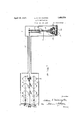
' A satisfactory forinof boiler for the purpose indicated is illustratedin the drawings, Figure 'VII, byway of example. a This part ofthe apparatus consists, preferably, of an unlined globular iron shell .rotatably mounted on trunnions 21 and 22, disposed co-.
hole cover inposition. The steamis admitted 7 through a steam supply pipe 27 extending axially through: one of the supportingtrunnions for the boiler on oneside thereof, a bleeder pipe 28 extending outwardly through the trunnion at the opposite side. The pipes 21" and 28 are bolted'togetherend to end by aid of terminal flanges 29 and 30 between which isinterposeda division plate 31 which intercepts communication between them. The shell 20revolves on its trunnions about the fixed pipes27and28-as an axis. The admission of steam to theboiler is controlled as by the usual valve 32, and th'e bleeder is equipped with the usualautomatic trap, not illustrated.
Associated with the bleeder, a hand-operated valve 35 and pipe are preferably employed, the valve being so placed and constructed that it may he operated,when the softening operation iscompleted, to relieve the boilerfrom the larger part of its internal pressure 1. and of-much'of the liquid contents.
Disposed at the side of the boiler preferably diametrically oppositethe manhole is, a blowoff pipe having a'valve 36 and which is adapted to be connected by a suitable-union 38 to.
a drain pipe or hose 39 leading to a sewer or other dischargepoint. 'The interior of the boiler around the outlet tothe blow-oil pipe is provided preferably with a. perforated plate or screen 40 of sufiicie-nt fineness as a means to retain in the boiler substantially all of the useful materialrwhile. allowing the waste liquor to pass without material interference with drainage. his construction is much. cheaper and simpler than the usual blow-pit used in pulp-making operations, and
the c'o'st of plant; construction. 7 V
' After the liquor has drained off, the remain ing contents remaining in the boiler may be washed, as vloy meansof an ordinary hose or the likeinserted-through the manhole of the boiler, until all of the refuse liquor and its contents are washedout, such washing also removing substantially all of the remaining results, in itself. in a substantial reduction indissolved and soluble matter notcarried off with theliquor in drainage; This washing operation in the boiler consumes only a few minutes, and may, under certain conditions,
be omitted in View of a subsequent washing boiler, disposed at the top thereof,
operation later mentioned which is effected after the materialleaves the boiler.
- After the wasteliquor has been withdrawn and the washing in the boiler, if any, completed, the blow-off pipe union38is disconnected from the drain pipe 39, and the boiler is given say a. half turnso as topermit the softened and washed material to drop from the boilerinto a receptacle 41. -This receptacle, as.shown in Figure-VII, is preferably constructed with-its sides converging'toward the bot-tom so as to concentrate thematerial in it toward a screw conveyor 42. r This screw conveyor carries the previously treated .material from the receptacle 41 to a conveyor 43 .(Figures 11, IX, and X)' thatfis prefer-- ably a chain conveyor compr1sing cross-bars 44gof th'e usual type," and operating onan incline as shownin Figure. X. In the, run of this conveyor, which is used for conveying the material, thebars 44- pass above and in close] contact with a screen 45' which is of comparatively fine'mesh. Located above .the' screen 45 and cross bars 44 is awasher, for example, a set-of shower pipes 46 which thoroughly sprinkle and wash the material as it is carried up over the said screen 45, the
water escaping through thescreento a sewer.
conduit or other means of discharge. I When thewashed materialfinally leaves the end 47 of the screen 45 it is carried by the conveyor .43 above a'series say of three equalization tanks50, 51, and 52, over a floor 53 that has an imperforate surface save for the provi-' sion in it of a corresponding numberof openings 55,, 56', and 57, above the equalization tanks aforesaid, respectively. Each of the said openings is equipped with a means for controlling and regulating its discharge as, in effect, an adjustable sliding gate. When the conveyor mechanism is running. as previously described, the gate for the opening is,as shown in Figure IX, opened about onethird' of the way; the gate forthe opening 56. is opened two-thirds of the way; and the gate for the opening 57-is fully opened so as .to clear the entire opening- In this way the material carried by the conveyor 43 is distributed equally among the aforesaid equalization tanks, this distribution being maintained until the said tanks are filled to the desired extent. The tanks, of whatsoever number, are collectively'of sufficient ca pacity to receive a number of batches of treat-- its ing a substantially uniform consistency of V the'contents, regardless of slight immaterial variations of results incidental to said treatments. A duplicate set of tanks and associated elements may .be placed as shown in FigureIX, at the'other side of the conveyor 43 from thetanks 50, 51, and 52.
exam le aree ui )ed res ectivel Y with a i-- t'ators 58, which are preferably rotary, driven by anys'uitable connections, as by gearing and shafts shown, and which are connected to-amotor, notillustrated, or other suitable source of driving power. Each of'the said tanks is connected to a water supply. Preferably the water used in the tanks is conden- 1 sation water from the paper machine driers s of similar i'nachines.
convenience in conveying the material, as
by pumping it, to the point where the neX operations are performed. r
a centrifugal stock pump 61, connected to a header'62, the header in turn being connected by valve-controlled pipes 63 to the different equalization tanks, so that the pump 61 may conveniently be connected to any tank desiredl The pump 61 is also connected as by a suitable pipe 65 to an elevated-flow box 66, Figures XII and XIII, containing three compartmentst'z', 68, 69, Figure XXI. The material-fir-stenters the compartment 67 and pa'sses'through a regulating gate 71 into the comp rtment 68 and through an outlet TQtothe upper one of a series of fiber separators d scribed in detail later on. The compartment 69 is designed to receive overflow from the comp;
intoan outlet 7% for returning the overflow and stock carried therein to the storage tank from which it came. The return connections for theoverfiow are not shown in detail, but
any construction satisfactory for the purpose:
. I 7 may be used.
The stock in suspension leaving through the outlet 72 enters a spread box 76 serving to spread th low of the stock to form a flat sheet con'fo iing in width'to the'throat or 77 of a fiber separator 78, first or upper one of'a' series The flow to the spread nd regulated by a suitle regulatin gate 71.
intake opening constituting the box 76 is COHtTOHQd a able adjustment of t The embod ment of my invention illustrated in the drawings, employs,by way of example, four separators arranged on a descending incline. They all alike, with a single difference hereinafter explained, and a description ofone of them, accompanied by an explanation of the difference mentioned, will be sufficient.
kssociatedwith the equalization tanks is ment 67, over darn or weir '13,
ass-yrs The separator. 78. resembles in. a great many respects the swing, hammer machines; used; fOrIpulveriZing;oresand clays, and, to av lim itedextent, certain vegetable growths,.such as kelp and sugar cane. Such prior machines which have been used. forpulverizihg. purposes are, h0wever,.unsuit'able forthe present purpose, and c'ertain'changes in them are re' quired't'o be made in order to securethedesired efiect upon the material passing: through. the machine.
The prior machines employed various forms of gratings and cutting bars-,giving a cutting an'd pulverizing action which is highly'undesirable to the extent of beingzsubstantially prohibitive in the treatment of the raw stock in order't'o carryoutmy present in.- vention..
The separator or machine 78xemployed' in the present instance comprises a rotor 81, Figures XIV and XV, consisting. of a mum-- leer of d ks'supporting crossbarsor: rods 82, upon which rods are loosely pivoted iron plates or' centrifugal hammers 83; The throat or intake opening-'77: of 'themachine 78 opens into a hopper provided with bars 8% which are adjustable to cooperate with the ends of the plates 83 whenthe rotor'81 is turning. in the directionof'the arrow: The best results, for present purposes, are ob tained when the bars 84 are so adjusted as; to leave an'appreciable gap between. the ends of the plat-esand'the bars;
l'nthe prior machines used' forthe other purposes above mentioned, the plates 83 usually were constructed from stock of'an inch thick, but in the present machine these plates are of an inch thick,1.and i approxi mately twice as many oflthe lighter and thinner plates are used as were used in the older A construction, the lighter and thinner plates being held apart on their pivots as by spacers between them.
In the prior machines the lower: part of the enclosure forthe rotor was-composedcof. a series of: sharp-edged cutter bars cooperate ing with thepivoted platesor hammers to. cut the material between the hammers and: thebars. Asa result, the previousmachinespulverized the. material, an effect which, as:
above indicated, is wholly undesirable for present purposes. The presentmachines have a bottomplate85 witlrasmooth concave surface substantiallycoaxial" with the axis 86 of the rotor 81. The plate 85in the separator is provided with numerous circular perforations 87, Figure XVII, which arepreferably of an inch in diameter, although the size ofthe perforations may be slightly increased or decreased according to the result desired.
Considered as a Whole, the increased number of light-weight plates or hammers 83, and the smooth interior and perforations de scribed, cooperate to brush the material against the interior of themachine, causing,
thereby, a separation ofithe fibers, asdistina series of slots, 93- -(Figure XVIII) which are preferably of an inch Wide and 1 inch long, the slots extending in a circumferential direction or parallel to the direction of movement of the plates 83. This slotted construction results in retaining all of the material in the interior of the separator until the fibers have beenjseparated sufiiciently. for them to brush through or escape through the slots. e
By the time the material has passed through the last separator, the woody portions will have been reduced to fibers having ahair-like appearance, many of the'fibers being of considerable length and substantially free one from another. Others o-fthe fibers will be only partially separated one from another, resulting in what is, in effect, a coarse fiber. a
For separation of the average lengthsof wood fiber, the fiber separators, say four in number, operate consecutively'upon the material, and means are provided for directing the flow from one 'separator'to the next until the separating operation is completed. v This directing means is, however, so constructed that by opening a suitable by-pass, one or more of the separators may be cut out, if the full complement thereof is unnecessary to the attainment of the degree, of separation desired.
'Inaddition to the by-pass, means are also I preferably provided for regulating the water content of the flow, a change in the .water contenteffecting a changein the results produced in each machine. In other words, the progress of the material through any one of the separators may be sped up -or retarded by regulating the amount of water, a decrease in the amount of water causing a longer .dwellanda greater degree of fiber separation, and an increase inthe water supply resulting in a lesserdegree of separation and a coarser condition of the fiber. V The regulation of the water content also gives a flex'is, bility in the operationof the separators,
which makes it possible to adjust or regulate their operation, according to the species of the 60 wood in the raw material. Y
- ing of the separator 88, which opening is like 91 and '92 the bottom plate85, instead of.
upon a chute or trough97, which, at itslower the opening 77, previously describedin connection with the separator 78. The separator 88' is provided with asimilar slide or trough 94 leading to the separator 9 1,and the separator 91 in turn has a trough or slide 90 leading to the final separator .92. Located near the lower end of each ofthe slides or troughs (90, 94, 95,), is a dam 89 which may be opened to admit or: lowered to prevent the flow from the preceding separator tothe next one. lVhen the darn is lowered, aremovable plug, not shown, is withdrawn fromgan outlet 96, allowing the fiowwhich would otherwise have passed tothe next separator to fall end, communicates with a, trough or' spout V 98, inclined as shown, and provided with openings in the bottom" above the stocktanks employed. These openings may be equipped with suitable gates or slides so asto-direct the flowof the stock to anyone or all oft-he tanks desired. Y
While the slides 90, 9 4 and' were previously described in such away as to indicate that they are'continuous or imperforate sur:
faces, it is preferred to construct themof wire mesh. which will allow a separation of the water and stock. Below such screens,90, 94, and 95, imperforate slides or bottoms are pro vided having respective outlets 101, 102, and
103, each equipped with a valve 104. Normally, the valves 10% are closed, and after the spaces under the screens havefilledup with waterfthe further flow is directed into the separators. Whenever it is desired toremove a part of the water before the flow enters the next separator, the valve in the corresponding outlet 101, 102, or 103, is set to allow all or any desiredpartof the water content to escape intoa trough leading to the returnwater tank 106. ,In addition to the outlets 101, 102, and 103, for allowing consequent speeding of the action in that V particular machine,- Only one of the pipes 107 .is shown inthe drawings, but it shouldbe understood that each separator has the same water supply arrangement for the'purpose stated. 7 The flow of materialleavingthe final separator, or the last onein operation if one or more of the separators has-been-cut out,
goes to the trough 98, which'has previously beenreferred to in connection withthe way ter control, and thento whichever one of a series of stock tanks 111, Figures II' and XII, is in condition to receive the stock. These stock tanks are equipped with preferably rotary agitators 110,each driven as by a gear connection 112 and 113 through a shaft 114 connected inany desired way with a motor 115. The stock issusp ended in the tanks in a volumeof Water sufficient to giveit a consistency of about a Qper cent of stock.
Thetanks'areall connected to a header 118 equipped with'a separate valve 119, whereby the tanks may be independently connected to and disconnected from the header. The header is connected-to a stock pump of suitable construction and capacity for carrying the stock to a regulating box like-the flow box shown in Figure XXI, but located above the rod mill shown, for example, in Figure l v Said regulating box suppliesst-ock in the required regulated amount-to the rod mill, the excess stock in theregulating box being automatically returned to stock tank.
ltis sufficient ,forpresent purposes to say that the stock from stock tanks is conveyed as required toa standard Fourdrinier orcylinder paper makingmachine tor the purpose of forming and converting it into paper, indicated at 'A. in Figure II.
The apparatus and process as so far de scribed can be used in producing the fibrous stock and the finished paper from any of the softer woods. It is, however, preferable :to use what maybe termed the long-fiber woods, particularly satisfactory results having been obtained from sugar and white 'pines, and from fir. Fir is particularly suitable for the purpose, and a percentage of fir included'wi'th other woods increases the desirable qualities of the finished product.
The stock material may be reduced to pieces of a suitable size for the subsequent operations in any suitable way. Preferably, however, a conveyor system, such, for example, as is designated generally as 131 in Fig Iure 1, conveys the raw material to a point abovethe hopper 1 32 ofa chipper This chipper is preferably of the disk type, with knives 134' which are adjustable to regulate the sizeor" the chips. The process as a whole is facilitated by keepingall of the chips under a mar-1i mum thickness of one inch and a length or" approximately two inches. The precise length isnot of importance;-but the maximum length indicated is preferred,because it has been found to be the best one for satisfactory softening and fiberizinn.
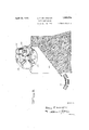
After passing through the chipper the chips fall into a bin 140, preferably having sides and bottom directing the chips to a belt-conveyor 141. The conveyor is inclined upward to elevate the chips to a hopper or chute 142 leading into the interior of a rotary chip screen 144, Figures I and V. This screen may consist of two tubular screens-145 and 1&6, one within the other, the inner screen beingof any predetermined mesh which will screen .out from .the chipped material any Part which is too coarse or too long for use tothe best advantage. Tithe outer screen 145 the wood is effectually decorticated,-and-the bark and other objectionable waste substance is separated from thefibrous or decorticated is of a finer mesh :thanlthe inner screen, and may @be employed,"-if desired, to screen lout dusta-nd particles which are toov small toserve a useful purpose in-thefinal product.
The screen 144-,asshown, is on an inclined axis, and when the screened material eventually reaches the lower end of 1t, the re1eets leave the inner screen and may be earned by a suitable conveyor (not shown) to a rechipper or crusher, or disposed of in any desired way. The material leaving the lower end of the outer screen drops upon a'beltconveyor 1417 which runs to a chip-bin conveniently located above the boiler hereinbefore described, from which bin the chipped material is removed for use in charging said boiler. I v
While the foregoing description has gone somewhat into great detail with respect to some of the various features of-the invention and ideas, it is not the intention to limit the definition of my invention to such details except as theymay be included in the followmg claims.
The foregoing specification includes description of apparatusthatin its several ,parts is adapted to'be combined and coordinated in such manner as the carrying out of my inventlon requires. 1 shallnow, by way of description of operation and disclosure in further detail ofwhat constitutes my invention, specify the manner of the combination and of coordination referred to in the last preceding sentence.
Accordingly, it is first in order to specify that, in the carrying out of-myi-nven-tion, raw material or wood wrththe bark on it that is to be fiberized isfirst supplied in the formof billets of suitable or convenient dimensions to the barking-machine illustrated, byway of example, in Figures XXIV, XXV, and XXVI. By the operation of said machine.
raw material, which is prepared for use by the barking machine.
he decorticated billets are then removed from the barking -machine and by any suitable and preferred means of conveyance fed into a suitable mach-me for reducing the hi1- lets to small blocks or particles of substanthe chip screening apparatus shown, for ex.-
ample, in Figure V v (bfthe drawings, delivery be ng made, the manner adreadyidescribed,
After the softenlng operation, effected in the boilers 20, for example, the softened mate rial is, as by mechanism illustrated in Figures IX, X, and XI, and specified in detail with reference thereto, conveyed to and distributed into the selected one of the various equalization tanks 50, 51, and 52, for example, where the material is, by the addition of water, converted into a suspension substantially of the consistency hereinbefore specified;
In that specified consistency, the material in suspension is conveyed, as by the pumpfil and pipe 65, to the flow box 66, substantially in the manner hereinbefore specified with reference to Figures XII and XIII.
From compartment 68 of the flow box, as through the outlet 72, the stock material in suspension passes in the manner and with the effect already specified, to the fiber separators (Figures XIV-XVIII, for example) where it is partially fiberized and separated, substantially in the manner and for the purpose hereinbefore specified.
The stock in suspension is passed from the fiber separators to the intake 148 of the rod mill wherein, by repeated operations, it is fin ally fiberized and the fibers are afterwards filamented into lengths of substantially admeasured standard, the fibers are separated into filaments of substantially uniform lengths suitable for forming and converting it into paper, substantially in the manner and by the means specified. V
The rod mill is preferably of the type illustrated in Figures XXII and XXIII, and which is so well known as not to require description in detail. It is deemed suificient to specify that it embodies in a rotative case 149 having a plurality of separate rod compartments 150, a complement in each compartment of alined metal rods 151. In consequence of the rotation of the case 149, a rolling and beating action of the rods within the several compartments upon the fibers fed into the mill ensues with the efiect upon them of complete filamentation. The case is surrounded by two cylindrical screens 152 and 153 having meshes of different degrees of fineness which serve to separate out of the mass, fibers of such fineness as will pass the outside screen 153 and discharge said fibers from the mill into a sluice-way 155. Fibers which are too coarse to pass the screen 153 are automatically returned into the compartments'150 and are there subjected to repetition of the action of the rods 151 upon them, until they are ultimately reduced thereby to such degree of fineness as to pass the screen 153.
From the sluice-way 155 of the rod mill,
the stock or fibers in suspension goes, by any suitable means of conveyance, to the screen shown in Figures XIX and XX, which serves to screen out all fibers of excessive lengths and render them ready for final conversion of 1 them into paper by the operation of the paper makingmachine already indicated at A as supplying the final step of my process.
What I claim is: V
1. The new and improved method ofmaking paper which consists in first reducing long fiber wood to a suitable size by passing it through a chipper and maintaining the chips in a predetermined size, conveying the chips through a chip screen conducting the treated chips to a boiler and subjecting them to a softening operation, selectively conducting the chip material to equalizing tanks where the material is by the addition-of water maintained insuspension, conveyingthe material under pressure to a flow box, then to a fiber separator, and conducting the material in suspension from the fiber separator to a reducing mill where the fibers are sep arated into filaments of substantially uniform lengths for forming and converting into paper. a
,2. The new and improved method of making paper which consists in conducting the raw material or wood with the bark on it in the form of billets to a barking machine so as to efi'ectively decorticate the waste substance from the raw material, reducing the decorticated billets or chips to substantially uniform dimensions, conducting the chips through a screening apparatus to a boiler so asto subject the same to a softening operation, passing the soft material through equalizing tanks where the material by the addition of water is maintained in suspension, forcing the material under pressure to a flow box, passing the material in suspensionifrom the fiow box to a fiber separator where it is partially fiberized and separated, conducting the material in suspension from the fiber separator to a reducing mill where the material is finely fiberized and the fibers filamentcd into substantially admeasured standard lengths, and converting the fibers so pro 'duced into paper.
In testimony whereof, I have hereunto set my hand.
, ARTHUR E. MILLINGTON.
Priority Applications (1)
| Application Number | Priority Date | Filing Date | Title |
|---|---|---|---|
| US408564A US1853774A (en) | 1929-11-20 | 1929-11-20 | Paper manufacture |
Applications Claiming Priority (1)
| Application Number | Priority Date | Filing Date | Title |
|---|---|---|---|
| US408564A US1853774A (en) | 1929-11-20 | 1929-11-20 | Paper manufacture |
Publications (1)
| Publication Number | Publication Date |
|---|---|
| US1853774A true US1853774A (en) | 1932-04-12 |
Family
ID=23616781
Family Applications (1)
| Application Number | Title | Priority Date | Filing Date |
|---|---|---|---|
| US408564A Expired - Lifetime US1853774A (en) | 1929-11-20 | 1929-11-20 | Paper manufacture |
Country Status (1)
| Country | Link |
|---|---|
| US (1) | US1853774A (en) |
Cited By (1)
| Publication number | Priority date | Publication date | Assignee | Title |
|---|---|---|---|---|
| US3154464A (en) * | 1953-04-25 | 1964-10-27 | Guy Victor Constant Dosselaere | Plants for washing and defiberizing fibrous material |
-
1929
- 1929-11-20 US US408564A patent/US1853774A/en not_active Expired - Lifetime
Cited By (1)
| Publication number | Priority date | Publication date | Assignee | Title |
|---|---|---|---|---|
| US3154464A (en) * | 1953-04-25 | 1964-10-27 | Guy Victor Constant Dosselaere | Plants for washing and defiberizing fibrous material |
Similar Documents
| Publication | Publication Date | Title |
|---|---|---|
| US2008892A (en) | Method of manufacture of pulp | |
| US3011220A (en) | Apparatus for separating mixtures of coarse and fine materials | |
| US1843467A (en) | Paper manufacture | |
| US2912174A (en) | Method and apparatus for the treatment of paper stocks | |
| CN111118956A (en) | Production method of regenerated high-strength corrugated base paper with ultralow gram weight | |
| US2358827A (en) | Process for producing flour | |
| US1947106A (en) | Method of producing absorbent felt | |
| US2374046A (en) | Method of disintegrating cellulosecontaining structures | |
| US1853774A (en) | Paper manufacture | |
| US2648261A (en) | Fiber disintegrator and separator | |
| US1960106A (en) | Method and apparatus for reconditioning paper stock | |
| US3684651A (en) | Digestion of fibre pulp from vegetable raw material including pulp level controls | |
| US1894577A (en) | Production of fiber | |
| DE60112730T2 (en) | METHOD AND DEVICE FOR TREATING GRINDING | |
| US1681118A (en) | Process of extracting, separating, and utilizing the starch and protein contents of rice | |
| US1885334A (en) | Process and equipment for forming sheets | |
| US1907548A (en) | Process of subjecting fibers to the action of gases | |
| US1913607A (en) | Method of preparing pulp | |
| US1857316A (en) | Manufacture of wall-board and the like | |
| US2910398A (en) | Asphalt dispersion in waste cellulosic material | |
| US2727439A (en) | Apparatus for treating pulp | |
| US1847050A (en) | Method of treating bagasse | |
| US1897620A (en) | Continuous process of reducing or reforming wood or other fibrous material | |
| US2113297A (en) | Process and apparatus for the manufacture of paper products | |
| US1878228A (en) | Paper manufacture |