US1853750A - G steiner - Google Patents
G steiner Download PDFInfo
- Publication number
- US1853750A US1853750A US1853750DA US1853750A US 1853750 A US1853750 A US 1853750A US 1853750D A US1853750D A US 1853750DA US 1853750 A US1853750 A US 1853750A
- Authority
- US
- United States
- Prior art keywords
- switch
- ignition
- current
- battery
- quick
- Prior art date
- Legal status (The legal status is an assumption and is not a legal conclusion. Google has not performed a legal analysis and makes no representation as to the accuracy of the status listed.)
- Expired - Lifetime
Links
- 238000010586 diagram Methods 0.000 description 14
- 238000002485 combustion reaction Methods 0.000 description 12
- 230000000875 corresponding Effects 0.000 description 6
- FPRULFHDSFKYBV-UHFFFAOYSA-N 3-amino-N-[(4-chlorophenyl)methyl]-4,6-dimethylthieno[2,3-b]pyridine-2-carboxamide Chemical compound S1C2=NC(C)=CC(C)=C2C(N)=C1C(=O)NCC1=CC=C(Cl)C=C1 FPRULFHDSFKYBV-UHFFFAOYSA-N 0.000 description 2
- 241000505673 Scintilla Species 0.000 description 2
- 230000001627 detrimental Effects 0.000 description 2
- 230000036633 rest Effects 0.000 description 2
- 230000003584 silencer Effects 0.000 description 2
- 238000004804 winding Methods 0.000 description 2
Images


Definitions
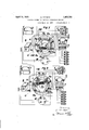
- Figs. 1 to 6 of the accompanying drawings show a constructional example of the quickaction change-over switch in various sections and views.
- Fig. 7 is a diagram of connections for instance for two sources of ignition current, namely for a magneto and battery ignition with the quick-action switch in the position in which the magneto ignition is switched on and
- Fig. 8 the corresponding diagram with the quick-action switch in the position in which the battery'ignition is switched
- Fig. 1' is a vertical section in which U is the switch casing, T the cover thereof and V the rack casing.
- C is the shaft of the quick action switch, one end of which is provided with teeth D which mesh with the rack E and the other end of which is provided with an arm F.
- the shaft C is surrounded by a sleeve G on which is mounted an insulating body J in which a contact piece K for the high tension circuit and contact pieces K and K, for the low tension circuit are embedded.
- the upper end of the sleeve G carries an arm L which is connected to the arm F by a spring (.2. H represents the outgoing high tension cable and is connected to the electrode 0 P, M and 31, 32 are sliding contacts for the low tension circuit.
- Fig. 2 is a plan view of the change-over switch in part section. It shows the sleeve G, the insulating body J with the contact pieces K K K the electrodes 0 O2, 0 the sliding contacts P, M, 31 and 32.
- HB and HM are the input high tension cables from the battery coil or from the ignition magneto apparatus.
- Figs. 3, t and are horizontal sections through the casing cover T of the switch (according to Fig. 1). They show different positions of the quick-action switch, Fig. 3 showing the position of the two arms L and F of the sleeve G and of the switch shaft C in which the quick-action switch is in the position in which the magneto ignition is switched in, and Fig. 4L the position of these arms in which the quick-action switch is in the position in which the battery ignition is switched in.
- Fig. 5 shows an intermediate position of the two arms L and F.
- Fig. 6 is a plan View of the quick-action switch shaft C with the toothed wheel D which meshes with the rack E.
- the rack E is fixed on a shaft R and is held in one extreme position by a spring S.
- Figs. 7 and 8 are the diagrams of the connections for the magneto for the battery ignition current source.
- the quick-action switch is shown in a horizontal section through the switch casing V (Fig. 1)
- V is the magneto apparatus
- B the battery
- TV the switch apparatus, with the levers for starting, for switching the two sources of ignition current on and off and for switching the different lights on and off.
- Y is the common high tension current distributor for the two ignition systems, which also contains the interrupter of the primary circuit of the battery ignition system.
- X is the ignition coil of the battery ignition system with primary and secondary winding and with series resistances.
- the magneto apparatus current is disconnected, while the battery current is connected.
- the battery current circuit is closed through the contact piece K as the sliding contacts 31 and 32 are connected and also the high tension circuit as the electrodes 0 and 0 are connected through the contact piece K while the high tension circuit of'the magneto apparatus is open as the electrodes 0 and 0 are not connected together.
- the interrupter of the magneto apparatus which even when the quick-action switch is in the position in which the battery ignition is connected up is turned positively by the motor, is short circuited owing to the sliding contacts P and M being connected by the contact piece K and the interruption of the primary current thus ceases.
- a dual ignition system for an internal combustion engine having one sparking plug per cylinder comprising a battery and coil source of high tension current, a magnetosource of current, a single high tension distributor and a single quick-acting changeover switch without an intermediate position.
- a dual ignition system as claimed in claim l wherein the switch comprises a shaft surrounded by a sleeve on which is mounted an insulating body, said insulating body carrying contacts for the high and low tension circuits of the battery and magneto sources of current.
Description
April 12, 1932. STEINER 1,853,750
IGNITION SYSTEM FOR INTERNAL COMBUSTION ENGINES Filed April 22, 1930 3 Sheets-Sheet l c:n I \IU I n I '1... 1
INVdNTd Q April 12, 1932. G, STEINER 1,853,750
IGNITION SYSTEM FOR INTERNAL COMBUSTION ENGINES Filed April 22, 1930 3 Sheets-Sheet 2 Fly. 3
April 12, 1932. STElNER Y 1,853,750
IGNITION SYSTEM FOR INTERNAL COMBUSTION ENGINES Filed April 22, 1930 3 Sheets-Sheet 3 6- S'fe/ner fH/s Patented Apr. 12, 1932 UNITED STATES PATENT OFFICE GOTTLIEB STEINER, OF OBACH SOLOTHURN, SWITZERLAND, ASSIGNOR T SCINTILLA AKTIIINGESELLSCHAFT, OF SOLOTHURN, SWITZERLAND IGNITION SYSTEM FOR INTERNAL COMBUSTION ENGINES Application filed April 22, 1930, Serial No. 446,318, and in Germany May 13, 1929.
In ignition systems of internal combustion engines with a single row of sparking plugs and more than one source of current the change over from one source of ignition current to the other has hitherto been effected by hand operated levers. With such an arrangement it frequently occurred that these change-over levers come to rest in an intermediate position, so that neither one source of ignition currentnor the other was in operation, causing misfires or irregularities in the enginewith their detrimental results. The engine might come to rest or ignitions might occur in the silencer or, on the members of one source of current being put in operation,
the corresponding members of the other were not yet put out of operation, which also was of no advantage.
According to the present invention, for overcoming these disadvantages when one source of ignition current is connected up the corresponding members of the other source of ignition current are made ineffective by positive means and through the provision of a quick-action switch an intermediate position of-the switch is made impossible.
Figs. 1 to 6 of the accompanying drawings show a constructional example of the quickaction change-over switch in various sections and views. Fig. 7 is a diagram of connections for instance for two sources of ignition current, namely for a magneto and battery ignition with the quick-action switch in the position in which the magneto ignition is switched on and Fig. 8 the corresponding diagram with the quick-action switch in the position in which the battery'ignition is switched Fig. 1' is a vertical section in which U is the switch casing, T the cover thereof and V the rack casing. C is the shaft of the quick action switch, one end of which is provided with teeth D which mesh with the rack E and the other end of which is provided with an arm F. The shaft C is surrounded by a sleeve G on which is mounted an insulating body J in which a contact piece K for the high tension circuit and contact pieces K and K, for the low tension circuit are embedded. The upper end of the sleeve G carries an arm L which is connected to the arm F by a spring (.2. H represents the outgoing high tension cable and is connected to the electrode 0 P, M and 31, 32 are sliding contacts for the low tension circuit.
Fig. 2 is a plan view of the change-over switch in part section. It shows the sleeve G, the insulating body J with the contact pieces K K K the electrodes 0 O2, 0 the sliding contacts P, M, 31 and 32. HB and HM are the input high tension cables from the battery coil or from the ignition magneto apparatus.
Figs. 3, t and are horizontal sections through the casing cover T of the switch (according to Fig. 1). They show different positions of the quick-action switch, Fig. 3 showing the position of the two arms L and F of the sleeve G and of the switch shaft C in which the quick-action switch is in the position in which the magneto ignition is switched in, and Fig. 4L the position of these arms in which the quick-action switch is in the position in which the battery ignition is switched in. Fig. 5 shows an intermediate position of the two arms L and F. Fig. 6 is a plan View of the quick-action switch shaft C with the toothed wheel D which meshes with the rack E. The rack E is fixed on a shaft R and is held in one extreme position by a spring S.
Figs. 7 and 8 are the diagrams of the connections for the magneto for the battery ignition current source. The quick-action switch is shown in a horizontal section through the switch casing V (Fig. 1) For the rest in this diagram V is the magneto apparatus, B the battery, TV the switch apparatus, with the levers for starting, for switching the two sources of ignition current on and off and for switching the different lights on and off. Y is the common high tension current distributor for the two ignition systems, which also contains the interrupter of the primary circuit of the battery ignition system. X is the ignition coil of the battery ignition system with primary and secondary winding and with series resistances.
For bringing the quick-action switch from the position for magneto ignition into that ings. During this motion of the bar R the shaft C of the quick action switch and with it the arm F is turned in the counter clockwise direction, when "viewing Fig. 1 from above. While the lever F moves away from the stop A (Fig. 3) the insulating body with its projection A rests against the stop A (Fig. 7) until the centre line of the tension spring Q has moved into the axis of rotation of the switch (see Fig. 5). After passing beyond this middle position, the lever L and with it the insulating body J containing the Through the tension of the spring Q, the lever F is drawn at the same moment against the stop A (Fig. 4); the separate members of the quick-action switch are now in the position shown in Fig. 8.
In diagram 7 the high tension current passes through the magneto apparatus through the HM cable to the electrode 0 over the contact piece K and the cable H into the common high tension distributor Y and from them to the separate sparking plugs. In this system of connections the interrupter of the magneto apparatus is not connected over the sliding contacts P and M to the mass, as the contact piece K is only connected to M, but does not connect M and P; on the other hand, the interrupter of the magneto apparatus can be short circuited at will by a press-button P in the switching apparatus and the ignition thereby interrupted. For the rest it will be seen from Fig. 7 that in this position of the switch the primary circuit of the battery ignition system,which commences at the battery and leads over 3 and 20 of the switch apparatus into the battery ignition coil to the .4 point 20 and after flowing through the series resistance and the primary coil from the point 21 to the points 31 and 32 of the quick action switch, is interrupted at 31 and 32. The point 32 of the quick-action switch is connected to the primary connection 21 of the common high tension distributor and in the latter the current passes through the interrupter and from the point T to the mass. The contact piece K in the insulating body J is so arranged that in the position according to diagram 7 the sliding contacts 31 and 32 are not connected together so that even when the points 3 and 20 in the switch apparatus W are connected by the battery switch, the battery switch is disconnected. In this position of the quick-action switch the high tension current of the battery ignition coil X is also not connected to the high tension distributor Y as the contact piece K of the insulating body J is so arranged that the electrodes 0 and 0 are not connected together.
In the diagram 8, however, the magneto apparatus current is disconnected, while the battery current is connected. The battery current circuit is closed through the contact piece K as the sliding contacts 31 and 32 are connected and also the high tension circuit as the electrodes 0 and 0 are connected through the contact piece K while the high tension circuit of'the magneto apparatus is open as the electrodes 0 and 0 are not connected together. The interrupter of the magneto apparatus, however, which even when the quick-action switch is in the position in which the battery ignition is connected up is turned positively by the motor, is short circuited owing to the sliding contacts P and M being connected by the contact piece K and the interruption of the primary current thus ceases.
Through the special arrangement of the electrodes, sliding contacts and contact pieces in the change-over switch and through the employment of a quick-action switch with stops having'a definite position with respect to one another as described, it becomes possible to obtain a sure change-over from one source of ignition current to the other, so that when one source of ignition current is switched on the other is with certainty made ineffective and vice versa and that no intermediate positions of the switch, giving no ignition current, can occur.
What I claim is:
1. A dual ignition system for an internal combustion engine having one sparking plug per cylinder comprising a battery and coil source of high tension current, a magnetosource of current, a single high tension distributor and a single quick-acting changeover switch without an intermediate position.
2. A dual ignition system as claimed in claim 1 wherein the said switch in one position completes the secondary circuit of the magneto and removes a short circuit in its primary whilst both primary and secondary circuits of the coil are broken whilst in its other position the switch completes the primary and secondary circuits of the coil, opens the secondary circuit of the magneto and short circuits the primary circuit of the magneto.
3. A dual ignition system as claimed in claim lwherein the switch comprises a shaft surrounded by a sleeve on which is mounted an insulating body, said insulating body carrying contacts for the high and low tension circuits of the battery and magneto sources of current.
4. A dual ignition system as claimed in claim 1 wherein the switch comprises a shaft surrounded by a sleeve on which is mounted an insulating body, said insulating body carrying contacts for the high and low tension circuits of the battery and magneto sources of current, the upper ends of the switch shaft and the switch sleeve being provided with arms which are connected together by a spring.
In testimony whereof I have signed my name to this specification.
GOTTLIEB STEINER.
Publications (1)
| Publication Number | Publication Date |
|---|---|
| US1853750A true US1853750A (en) | 1932-04-12 |
Family
ID=3423658
Family Applications (1)
| Application Number | Title | Priority Date | Filing Date |
|---|---|---|---|
| US1853750D Expired - Lifetime US1853750A (en) | G steiner |
Country Status (1)
| Country | Link |
|---|---|
| US (1) | US1853750A (en) |
-
0
- US US1853750D patent/US1853750A/en not_active Expired - Lifetime
Similar Documents
| Publication | Publication Date | Title |
|---|---|---|
| US1853750A (en) | G steiner | |
| US1861417A (en) | Aeseiilschai t | |
| US2230508A (en) | Electric ignition and lighting | |
| US1882793A (en) | of anderson | |
| US685960A (en) | Electrical ignition device for explosion-engines. | |
| US1909855A (en) | Starting device for internal combustion engines | |
| US1557201A (en) | Poration | |
| US1817974A (en) | Internal combustion engine power plant | |
| US800418A (en) | Circuit-controller for explosion-engines. | |
| US808958A (en) | Spark-ignition system for explosion-engines. | |
| US2032775A (en) | Means for controlling starting motor and ignition circuits | |
| US1471741A (en) | Switch mechanism for automobiles | |
| US1964698A (en) | Double ignition fob internal com | |
| US1856561A (en) | Ignition system | |
| US1940614A (en) | Ignition mechanism | |
| US1305601A (en) | Ignition device for motor-vehicles | |
| US2124528A (en) | Electric ignition system | |
| US1501521A (en) | Ignition | |
| US846809A (en) | Spark-ignition system for explosion-engines. | |
| US648689A (en) | Igniting device for gas-engines. | |
| US1329508A (en) | Ignition mechanism for internal-combustion engines | |
| US2150996A (en) | Double ignition system for internal combustion engines | |
| US1347511A (en) | Ignition system | |
| US2301071A (en) | Engine starting mechanism | |
| US1258098A (en) | Ignition system. |