US1853717A - Bucket clean-out mechanism for conveyers - Google Patents
Bucket clean-out mechanism for conveyers Download PDFInfo
- Publication number
- US1853717A US1853717A US520003A US52000331A US1853717A US 1853717 A US1853717 A US 1853717A US 520003 A US520003 A US 520003A US 52000331 A US52000331 A US 52000331A US 1853717 A US1853717 A US 1853717A
- Authority
- US
- United States
- Prior art keywords
- shaft
- bucket
- clean
- finger
- conveyer
- Prior art date
- Legal status (The legal status is an assumption and is not a legal conclusion. Google has not performed a legal analysis and makes no representation as to the accuracy of the status listed.)
- Expired - Lifetime
Links
Images
Classifications
-
- B—PERFORMING OPERATIONS; TRANSPORTING
- B65—CONVEYING; PACKING; STORING; HANDLING THIN OR FILAMENTARY MATERIAL
- B65G—TRANSPORT OR STORAGE DEVICES, e.g. CONVEYORS FOR LOADING OR TIPPING, SHOP CONVEYOR SYSTEMS OR PNEUMATIC TUBE CONVEYORS
- B65G47/00—Article or material-handling devices associated with conveyors; Methods employing such devices
-
- B—PERFORMING OPERATIONS; TRANSPORTING
- B65—CONVEYING; PACKING; STORING; HANDLING THIN OR FILAMENTARY MATERIAL
- B65G—TRANSPORT OR STORAGE DEVICES, e.g. CONVEYORS FOR LOADING OR TIPPING, SHOP CONVEYOR SYSTEMS OR PNEUMATIC TUBE CONVEYORS
- B65G2812/00—Indexing codes relating to the kind or type of conveyors
- B65G2812/02—Belt or chain conveyors
- B65G2812/02267—Conveyors having endless traction elements
- B65G2812/02415—Conveyors having endless traction elements with load-carrying surfaces supported by traction means
- B65G2812/02613—Conveyors having endless traction elements with load-carrying surfaces supported by traction means the load-carrying surfaces being separated from each other, e.g. individual load carriers
- B65G2812/02673—Conveyors having endless traction elements with load-carrying surfaces supported by traction means the load-carrying surfaces being separated from each other, e.g. individual load carriers the load-carriers being arranged above, between or beside the traction means
- B65G2812/02683—Conveyors having endless traction elements with load-carrying surfaces supported by traction means the load-carrying surfaces being separated from each other, e.g. individual load carriers the load-carriers being arranged above, between or beside the traction means and fixed or non-movably linked to the traction means
- B65G2812/02693—Conveyors having endless traction elements with load-carrying surfaces supported by traction means the load-carrying surfaces being separated from each other, e.g. individual load carriers the load-carriers being arranged above, between or beside the traction means and fixed or non-movably linked to the traction means for vertical or inclined conveyance
- B65G2812/02702—Details
- B65G2812/02712—Loading or unloading means
-
- Y—GENERAL TAGGING OF NEW TECHNOLOGICAL DEVELOPMENTS; GENERAL TAGGING OF CROSS-SECTIONAL TECHNOLOGIES SPANNING OVER SEVERAL SECTIONS OF THE IPC; TECHNICAL SUBJECTS COVERED BY FORMER USPC CROSS-REFERENCE ART COLLECTIONS [XRACs] AND DIGESTS
- Y10—TECHNICAL SUBJECTS COVERED BY FORMER USPC
- Y10S—TECHNICAL SUBJECTS COVERED BY FORMER USPC CROSS-REFERENCE ART COLLECTIONS [XRACs] AND DIGESTS
- Y10S37/00—Excavating
- Y10S37/901—Bucket cleaners
Definitions
- WILLIAIIL I-I. BOSWORTI-I; F YONKEES NEW YORK, ASSIGN'OR TO GEORGE HAISS-v MANUFACTURING CO. INC., OF 1 ⁇ TEW YORK,.N..Y., A CORPORATION OF BUCKET CLEAN-OUT Mncnemsm roe convnynns Application filed. Mareh4, 1931. Serial no. 520,003.
- This invention relatesto bucket clean-out mechanism for conveyers, and is herein shown in connection'with an excavator of the type described in United States Patent No. ranted February 3, 1931, to Raymond O. I juices, Wagon loader and excavator.
- the general object of this invention is to provide a simple, reliable and. effective means for-automatically removing the mate rial from the bucketsat the dischargeend 2 of the'conveyersso as to successivelyv'condition the buckets for reception of the mate rial. at the pick-up end ofithe conveyer.
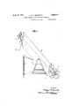
- Fig.1 Lis a; side view of'an excavator of the bucketrconveyer type, having the clean outqnechanism: embodying this invention associated'therewith;
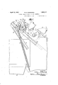
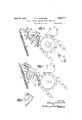
- Fig. 2 is an enlarged View, showing. in elevation the clean-out mechanism; with the cleaning fingers thereof positioned to be received by a bucket' as it approaches icleaningvposition;
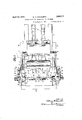
- Fig. 3 is a plan view of the mechanism as viewed from above 8 is a diagrammatic view showing the path that the cleaning fingers describe with respect .to a..abucket.vduring a.
- a Loaders or excavators of'the' type zaboves justablymounted on a traction device 11, by which the machine may be propelled from place to place and moved at slow speed to ward and into the materialrto be loaded or excavated, therebeing a powerunit such as entioned include a frame p-b C oy g aninternal combustion engine,-not;,shown,
- This conveyor 12 includes a plurality of buckets,13,"carried by aapair' of chains 14;,p-assin'g over pairs of sprockets 15 andlfi', respectively, the former ofwhich are secured to the 1111-1.
- a pair of supports 22,? such: as angle irons,,.the upper flangesof which are disposed in a plane parallel to the planein which the head shaft 18" may be adjusted longitudinally of the boom 10 by the adjusting means 19.
- These supports are connected together :at their outer ends by a transverse frame member 23,. and 'are. reinforced, for-the sake of rigidity, by a pair of angle brackets 24 suitably connected thereto and to the sides of theframe 10.
- the bearing plates 25 are held for longitudinal adjustment on the respective supports 22 by a plurality of bolts 26, which extend through the upper flange of the supports 22 and through elongated openings 27 formed in the lower flange of the bear ing plates.
- a gusset plate 28 Secured to the vertical flange of each of the bearing plates 25, is a gusset plate 28 which extends below theupper flange of the respective supports 22.
- an angle abutment plate 30 To each of the gusset plates 28, is secured an angle abutment plate 30, the outwardly projecting flange- 31 of which carries a rubber cushioning element 32, the function of which will hereinafter more clearly appear.
- a suitable bearing 33 in which is j ournalled a transverse shaft 34, the intermediate-portion of which is square in cross-section, and the opposite ends of which project beyond the respective bearing plates and are provided with a pair of substantially diametrically opposed arms 35 and 36, the former of which are connected to tension springs 37 which are anchored to the sides of the frame 10.
- Each of the arms 36 is pivotally connected to a link 38, having an elongated slot 40, which affords a lost-motion connection between the respective arms 36 and a pair of shock-absorbers 41, of a conventional dead beat type, .connected to the abutment plates 30, the lost-motion between the arms 36 and the shock-absorbers being af forded by reason of the fact that the connecting pins 42, by which the links 38 are connected to the torque arms 43 of the shockabsorbers, are slidable within the respective slots 40.
- a plurality of clean-out fingers 45 Secured to the squared portion of the transverse shaft 34 and intermediate the bearings 33, are a plurality of clean-out fingers 45 which are disposed in an aligned relation and are spaced from each other.
- Each of these fingers includes a spade-like end portion 46, adapted to enter the successive buckets at a tangent to a circle struck from the center of the head shaft 18 and intersecting the buckets at the point of clean-out-finger contact therewith as such buckets are presented tothe clean-out fingers.
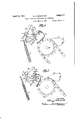
- the connector plates 50 are adapted to engage one of the flat faces of the square shaft 34, whereas the shoulders 51 of the respective connector plates are adapted to engage an adjacent face of such shaft as shown most clearly in Fig. 7.
- These cleanout fingers are detachably connected to the shaft 34 by a plurality of of bolts 45, which pass through the connector plates 50 and the shaft, and by a plurality of bolts 52, which pass through the rear of the connector plates and through the outwardly projecting flange 54 of an angle iron 55, which extends substantially throughout the length of the squared portion of the shaft 34 and is connected to the same by rivets 56, which pass through that shaft and the other flange of the angle iron 55.
- the clean-out fingers 45 are adapted to be engaged by the buckets and to enter the same as the buckets move about the sprockets 16 at the discharge endof the conveyer, it follows that the above-mentioned normal tangential relation of each such finger to the aforementioned circle, which is concentric with the head shaft 18, mus be maintained for any and all adjustments of such shaft that may be effected by the adjusting means 19; and it also follows that the center of the shaft 34, carryingsuch fingers, must be maintained at a given distance from the center of the head shaft 18 100 for any and all adjustments thereof.
- the shafts 18 and 34 are connected together by a pair of connector links 60 which insure the movement of the shaft 34 in a direction corresponding to and of an ex- 1 tent equal to the movement of the shaft 18, the two shafts being at all times maintained in fixed parallel planes by reason of the parallel relation of the upper flanges of the supports 22' to the plane of adjustment of the 110 shaft 18.
- These connector links 60 are pivotally mounted on the adjustable bearings 18' in which the shaft 18 is journalled, and are pivotally connected to the bearing plates 25 by bolts 61, which pass through the vertical 15 flanges of the respective bearing plates 25 and the gusset plates 28 secured thereto, it being noted that the link 60 appearing at the left in Fig.
- the buckets 13 collect at the pick-up end of the loader or conveyer the material to be handled and carry it along the upper reach of the conveyer chains to the discharge end of the conveyer.
- the clean-out fingers 45 are engaged by the inner wall of the bucket at the forward end thereof.
- the clean-out fingers together with the shaft 34, move about the axis of the latter against the tension of the springs 37 and in so moving they-sweep through the bucket from one position to another in a path indicated diagrammatically in Fig.
- a clean-out mechanism for a bucket conveyer comprising a pivotally mounted clean-out finger adaptedto be actuated by the bucket and to penetrate and sweep through the bucket during such actuation, tension means for resisting the sweeping movement of'said finger and for returning the same to its normal position upon completion of such movement,shockrabsorbing means for resistin'g the return of said finger to its normal position, andiconnecting means between said finger" and said shock-absorbing means operable to render said shock-absorbing means effective during only a part ofthe return movement of said finger.
- tension means for resisting thesweeping movement of said finger the bucket during such actuation, a connection between said shafts for automatically maintaining the latter at a given distance from the former while adjustment of the former is being” made, tension means for resisting the sweeping movement of said finger and for returning, the same to its normal position upon completion of such movement, and shock-absorbing means associated with the second-named shaft and automatically movable therewith uponadj'ustment of such shaft and adapted to resist the return movementof said finger to its normal position.
- a bucket clean-out mechanism comprising a support, a shaft rotatably and adjustably mounted on said support, a cleanout finger secured to the second shaft and adapted to be actuated by a bucket of the conveyer and to penetrate and sweep through the bucket during such actuation, a connection between said shafts for automatically maintaining the latter at a given distance from the former while adjustment of the former is being made, tension means for resisting the sweeping movement of said finger and for returning the same to its normal position upon completion of such movement, shock absorbing means associated with the secondnamed shaft and automatically movable therewith upon adjustment of such shaft and adapted to resist the return movement of said finger to its normal position, and connecting means between the second-named shaft and said shock-absorbing means operable to render said shock-absorbing means effective during only a part of the return movement of said finger.
- a chain bucket conveyer including a head shaft mounted for adjustment transversely of itself in a given plane and carrying a pair of sprockets over which the conveyer chains operate, and means for adjusting said shaft in said plane longitudinally of the chain reaches; of a bucket clean-out mechanism comprising a support, a shaft mounted on said support for adjustment transversely of itself in a plane parallel to the plane of adjustment of said head shaft, a clean-out finger secured to the second shaft and adapted to be actuated by a bucket of the conveyer and to penetrate and sweep through the bucket during such actuation, a connectionbetween said shafts for automatically maintaining the latter at a given distance from the former while adjustment of the former is being made, and tension means for resisting the sweeping movement of said finger and for returning the same to its normal position upon completion of such movement.
- a chain bucket conveyer including a head shaft mounted for adjustment transversely of itself in a given plane and carrying a pair of sprockets over which the conveyer chains operate, of a bucket clean-out mechanism comprising a support, a shaft mounted on said support for adjustment transversely of itself in a plane parallel to the plane of adjustment of said head shaft, a clean-out finger secured to the sec- 0nd shaft in a fixed normal relation to the WILLIAM H. Bos oRTH,
Description
April 12, 1932. w. H. BOSWORTH BUCKET CLEAN-OUT MECHANISM FOR CONVEYERS Filed March 4,- 1931 5 Sheets-Sheet 1 INVENTOR W4 M ATTORNEYS April 12, 1932. w. H, BOSWORTH 1,853,717
BUCKET CLEAN-OUT MECHANISM FOR CONVEYERS INVENTORL I 1 v 7mm M11, 4,11% BY v 1 W zg' a C h f 21 ATTORNEYS April 12, 1932. w. H. BOSWORTH BUCKET CLEAN-OUT MECHANISM FOR CONVEYERS Filed March 4, 1951 5 Sheets-Sheet 5 MW N mm m INVENTOR ATTORN EYS April 12, 1932. w. H.- BOSWORTH BUCKET CLEAN-OUT MECHANISM FOR CONVEYERS Filed March 1931 5 Sheets-Sheet 4 R O T N V m,
ATTORNEYS April 12, 1932. w. H. BOSWORTH 1,853,717
- BUCKET CLEAN-OUT MECHANISM FOR CONVEYERS Filed March 4, 1931' 5 Sheets-Sheet 5 INVENTOR ATTORNEYS Patented Apr. 12, 1932 UNITE stare:
WILLIAIIL I-I.: BOSWORTI-I; F YONKEES NEW YORK, ASSIGN'OR TO GEORGE HAISS-v MANUFACTURING CO. INC., OF 1\TEW YORK,.N..Y., A CORPORATION OF BUCKET CLEAN-OUT Mncnemsm roe convnynns Application filed. Mareh4, 1931. Serial no. 520,003.
This invention: relatesto bucket clean-out mechanism for conveyers, and is herein shown in connection'with an excavator of the type described in United States Patent No. ranted February 3, 1931, to Raymond O. I faiss, Wagon loader and excavator.
In the handling of sticky masses of material, such: as .certain kinds of mud, the buckets of a bucket conveyer become clogged with the material, which, due to its adhesive nature is=held .withinthe buckets, instead of discharged by gravity or by centrifugal force and gravity, at the dischargeend of the conveyer, with the result that the operation of theconveyer is impaired.
The general object of this invention is to provide a simple, reliable and. effective means for-automatically removing the mate rial from the bucketsat the dischargeend 2 of the'conveyersso as to successivelyv'condition the buckets for reception of the mate rial. at the pick-up end ofithe conveyer.
Other. objects and advantages of i the: in-
vention, will become apparent when taken in connection with the accompanying drawings,
Fig.1 Lis a; side view of'an excavator of the bucketrconveyer type, having the clean outqnechanism: embodying this invention associated'therewith; Fig. 2 is an enlarged View, showing. in elevation the clean-out mechanism; with the cleaning fingers thereof positioned to be received by a bucket' as it approaches icleaningvposition; Fig. 3 is a plan view of the mechanism as viewed from above 8 is a diagrammatic view showing the path that the cleaning fingers describe with respect .to a..abucket.vduring a. cleaningoperationa Loaders or excavators of'the' type zaboves justablymounted on a traction device 11, by which the machine may be propelled from place to place and moved at slow speed to ward and into the materialrto be loaded or excavated, therebeing a powerunit such as entioned includea frame p-b C oy g aninternal combustion engine,-not;,shown,
employed as a driving means for the traction device as Well as the bucket conveyer 12. This conveyor 12 includes a plurality of buckets,13,"carried by aapair' of chains 14;,p-assin'g over pairs of sprockets 15 andlfi', respectively, the former ofwhich are secured to the 1111-1.
mediate portion of a shaft 17 suitably journall'ed to thelower end of the frame or boom 10'fand the latter of which are 'carriedzbyahead shaft'18 which is mountedin the usual mannerfor adjustment longitudinally of the boom .by adjusting 'means 19,whe'r eby the connection between the above-mentioned power unit and the-conveyer chains 14, which drive the shaft 17', is such that this shaft isrotated in the-direction of the arroWA-in Fig. 1, whereby the material to be loaded or excavated is loosened bya plurality of picks 20 carried by the shaft 17 and whereby such loosened material is moved toward and into the-path of thebuckets 13tobe there picked picked up by-such buckets and carriedto the I 1 discharge end of theconveyer where itisres leased ordinarily under the-action of gravity and deposited in a loading hopper orchute 21 carried by the boom 10.. v j
,To theiuppe'r ends of the sides of the frame or boom 10, are connected a pair of supports 22,?such: as angle irons,,.the upper flangesof which are disposed in a plane parallel to the planein which the head shaft 18" may be adjusted longitudinally of the boom 10 by the adjusting means 19. These supports are connected together :at their outer ends by a transverse frame member 23,. and 'are. reinforced, for-the sake of rigidity, by a pair of angle brackets 24 suitably connected thereto and to the sides of theframe 10. On the upper flange of the supports 22,.are mounted a pair of angle bearingplates 25' the-lowerfiange of'each of which restsrupon the upper flange ofthere spective supports 22. The bearing plates 25 are held for longitudinal adjustment on the respective supports 22 by a plurality of bolts 26, which extend through the upper flange of the supports 22 and through elongated openings 27 formed in the lower flange of the bear ing plates. Secured to the vertical flange of each of the bearing plates 25, is a gusset plate 28 which extends below theupper flange of the respective supports 22. To each of the gusset plates 28, is secured an angle abutment plate 30, the outwardly projecting flange- 31 of which carries a rubber cushioning element 32, the function of which will hereinafter more clearly appear. Mounted in each of the bearing plates 25, is a suitable bearing 33 in which is j ournalled a transverse shaft 34, the intermediate-portion of which is square in cross-section, and the opposite ends of which project beyond the respective bearing plates and are provided with a pair of substantially diametrically opposed arms 35 and 36, the former of which are connected to tension springs 37 which are anchored to the sides of the frame 10. Each of the arms 36 is pivotally connected to a link 38, having an elongated slot 40, which affords a lost-motion connection between the respective arms 36 and a pair of shock-absorbers 41, of a conventional dead beat type, .connected to the abutment plates 30, the lost-motion between the arms 36 and the shock-absorbers being af forded by reason of the fact that the connecting pins 42, by which the links 38 are connected to the torque arms 43 of the shockabsorbers, are slidable within the respective slots 40. V
Secured to the squared portion of the transverse shaft 34 and intermediate the bearings 33, are a plurality of clean-out fingers 45 which are disposed in an aligned relation and are spaced from each other. Each of these fingers includes a spade-like end portion 46, adapted to enter the successive buckets at a tangent to a circle struck from the center of the head shaft 18 and intersecting the buckets at the point of clean-out-finger contact therewith as such buckets are presented tothe clean-out fingers. This relation of the clean-out fingers to the buckets, at the time the buckets are presented to the clean-out fingers, is necessary in order to insure a head-on contact between the entering ends of the fingers and the load in the bucket, it being understood that were the fingers un duly pitched forwardly of their normal position (Fig. 2), they would be subjected on their rear faces to the influence of the bucket load and would be pushed out of'the way by the contents of the bucket without being given an opportunity to perform the function for which they are intended. The spadelike end portion 46 of each finger is reinforced along its backby a rib 47, extending longitudinally thereof and terminating in a shank portion 48 which is formed integral with a connector plate 50 disposed at right angles thereto and provided with a shoulder 51. The connector plates 50 are adapted to engage one of the flat faces of the square shaft 34, whereas the shoulders 51 of the respective connector plates are adapted to engage an adjacent face of such shaft as shown most clearly in Fig. 7. These cleanout fingers are detachably connected to the shaft 34 by a plurality of of bolts 45, which pass through the connector plates 50 and the shaft, and by a plurality of bolts 52, which pass through the rear of the connector plates and through the outwardly projecting flange 54 of an angle iron 55, which extends substantially throughout the length of the squared portion of the shaft 34 and is connected to the same by rivets 56, which pass through that shaft and the other flange of the angle iron 55.
Inasmuch as the clean-out fingers 45 are adapted to be engaged by the buckets and to enter the same as the buckets move about the sprockets 16 at the discharge endof the conveyer, it follows that the above-mentioned normal tangential relation of each such finger to the aforementioned circle, which is concentric with the head shaft 18, mus be maintained for any and all adjustments of such shaft that may be effected by the adjusting means 19; and it also follows that the center of the shaft 34, carryingsuch fingers, must be maintained at a given distance from the center of the head shaft 18 100 for any and all adjustments thereof. To these ends the shafts 18 and 34 are connected together by a pair of connector links 60 which insure the movement of the shaft 34 in a direction corresponding to and of an ex- 1 tent equal to the movement of the shaft 18, the two shafts being at all times maintained in fixed parallel planes by reason of the parallel relation of the upper flanges of the supports 22' to the plane of adjustment of the 110 shaft 18. These connector links 60 are pivotally mounted on the adjustable bearings 18' in which the shaft 18 is journalled, and are pivotally connected to the bearing plates 25 by bolts 61, which pass through the vertical 15 flanges of the respective bearing plates 25 and the gusset plates 28 secured thereto, it being noted that the link 60 appearing at the left in Fig. 3 is cut away or recessed,'as shown at 62, so as to provide a notch through which 126 25, carrying the bearings 33 in which the 13c transverse shaft .1 34 is ournalled, to move longitudinally on the supports22in one di.-. rection or the other. If the shaft. 18 is moved ina direction to tighten the conveyer chains I I l4,.the'-bearing pl ates'will be caused to correspondingly 1n0ve,:and this is also true if the shaft is adjusted in: a direction to loosen the conveyer'chains 14,: the distance between the shafts 18 and 34 being thus maintainedthe same for all positions of adjustment that may be assumedby the shaft 18. After having adjusted the shaft 18, the bolts 26 are tightened, thereby locking the bearing plates 25.to thesupports22.
In operation, the buckets 13 collect at the pick-up end of the loader or conveyer the material to be handled and carry it along the upper reach of the conveyer chains to the discharge end of the conveyer. As the buckets 13 successively move over the sprockets 16, the clean-out fingers 45 are engaged by the inner wall of the bucket at the forward end thereof. By reason of this engagement, the clean-out fingers, together with the shaft 34, move about the axis of the latter against the tension of the springs 37 and in so moving they-sweep through the bucket from one position to another in a path indicated diagrammatically in Fig. 8, thus removing from the successive buckets any material that may, because of its adhesive nature, fail to fall from the buckets by gravity alone as they pass over the sprockets 16 into dumping position. During suchtime as the clean-out fingers sweep through the respective buckets, the torque arms 43 of the shock-absorbers 41 move from their positions shown in Fig. 4 to their positions shown in Fig. 7, the connecting pins 42 of the respective torque arms being permitted to move, in the meantime, from the lower ends of the slots 40 of the connector links 38 to the other end thereof. As the successive buckets are disengaged from the clean-out fingers 45, the transverse shaft 34 is rotated by the springs 87 in a reverse direction, thus retracting the clean-out fingers. This reverse movement of the shaft 34 is unrestrained during such time as the connector pins 42 of the torque arms 43 move throughout the length of the slots 40 of the connector links 38, but as these pins reach the outer end of the slots 40 an operative connection is established between the torque arm 43 and the connector links, with the result that the shock-absorbers become effective to decelerate the return movement of the shaft, which is finally and positively limited to its position shown in Fig. 2 by engagement of the arms 35 with the rubber cushioning elements 32, against which such arms normally rest.
What is claimed is:
1. A. clean-out mechanism for a bucket the" bucket and to penetrate. and sweep through the bucket during such actuation, tension means: for resisting the sweeping movement of said finger and for" returning the same to its normal position upon com pletion of such movement, and shock-absorbing means for resisting the return of. said finger to its normal position.
2. A clean-out mechanism for a bucket conveyer comprising a pivotally mounted clean-out finger adaptedto be actuated by the bucket and to penetrate and sweep through the bucket during such actuation, tension means for resisting the sweeping movement of'said finger and for returning the same to its normal position upon completion of such movement,shockrabsorbing means for resistin'g the return of said finger to its normal position, andiconnecting means between said finger" and said shock-absorbing means operable to render said shock-absorbing means effective during only a part ofthe return movement of said finger.
3. The combination with a chain, bucket conveyerincludingf an adjustable head shaft carrying a: pair of sprockets over which the conveyer chains operate, and means for adjusting'saidshaft longitudinally ofthe chain reaches; of a bucket clean-out mechanism comprising a support, a'shaft rotatably and adj ustably mountedon said support, a clean-, out finger secured to the second shaft and adapted. to b'e actuated. by. a. bucket of the conveyer and to penetrate and. sweepthrough the bucketduring' such actuation, a connection between said. shafts for automatically maintaining the latter at a given distance from the. former while adjustment of the former is being made, tension means for resisting thesweeping movement of said finger the bucket during such actuation, a connection between said shafts for automatically maintaining the latter at a given distance from the former while adjustment of the former is being" made, tension means for resisting the sweeping movement of said finger and for returning, the same to its normal position upon completion of such movement, and shock-absorbing means associated with the second-named shaft and automatically movable therewith uponadj'ustment of such shaft and adapted to resist the return movementof said finger to its normal position.
5. The combination with a chain bucket conveyer including an adjustable head shaft carrying a pair of sprockets over which the conveyer chains operate, and means for adj usting said shaft longitudinally of the chain reaches; of a bucket clean-out mechanism comprising a support, a shaft rotatably and adjustably mounted on said support, a cleanout finger secured to the second shaft and adapted to be actuated by a bucket of the conveyer and to penetrate and sweep through the bucket during such actuation, a connection between said shafts for automatically maintaining the latter at a given distance from the former while adjustment of the former is being made, tension means for resisting the sweeping movement of said finger and for returning the same to its normal position upon completion of such movement, shock absorbing means associated with the secondnamed shaft and automatically movable therewith upon adjustment of such shaft and adapted to resist the return movement of said finger to its normal position, and connecting means between the second-named shaft and said shock-absorbing means operable to render said shock-absorbing means effective during only a part of the return movement of said finger.
6. The combination with a chain bucket conveyer including a head shaft mounted for adjustment transversely of itself in a given plane and carrying a pair of sprockets over which the conveyer chains operate, and means for adjusting said shaft in said plane longitudinally of the chain reaches; of a bucket clean-out mechanism comprising a support, a shaft mounted on said support for adjustment transversely of itself in a plane parallel to the plane of adjustment of said head shaft, a clean-out finger secured to the second shaft and adapted to be actuated by a bucket of the conveyer and to penetrate and sweep through the bucket during such actuation, a connectionbetween said shafts for automatically maintaining the latter at a given distance from the former while adjustment of the former is being made, and tension means for resisting the sweeping movement of said finger and for returning the same to its normal position upon completion of such movement.
7. The combination with a chain bucket conveyer including a head shaft mounted for adjustment transversely of itself in a given plane and carrying a pair of sprockets over which the conveyer chains operate, of a bucket clean-out mechanism comprising a support, a shaft mounted on said support for adjustment transversely of itself in a plane parallel to the plane of adjustment of said head shaft, a clean-out finger secured to the sec- 0nd shaft in a fixed normal relation to the WILLIAM H. Bos oRTH,
Priority Applications (1)
| Application Number | Priority Date | Filing Date | Title |
|---|---|---|---|
| US520003A US1853717A (en) | 1931-03-04 | 1931-03-04 | Bucket clean-out mechanism for conveyers |
Applications Claiming Priority (1)
| Application Number | Priority Date | Filing Date | Title |
|---|---|---|---|
| US520003A US1853717A (en) | 1931-03-04 | 1931-03-04 | Bucket clean-out mechanism for conveyers |
Publications (1)
| Publication Number | Publication Date |
|---|---|
| US1853717A true US1853717A (en) | 1932-04-12 |
Family
ID=24070780
Family Applications (1)
| Application Number | Title | Priority Date | Filing Date |
|---|---|---|---|
| US520003A Expired - Lifetime US1853717A (en) | 1931-03-04 | 1931-03-04 | Bucket clean-out mechanism for conveyers |
Country Status (1)
| Country | Link |
|---|---|
| US (1) | US1853717A (en) |
-
1931
- 1931-03-04 US US520003A patent/US1853717A/en not_active Expired - Lifetime
Similar Documents
| Publication | Publication Date | Title |
|---|---|---|
| CN110254489A (en) | A kind of architectural engineering tipping bucket self-unloading dumper | |
| US2669338A (en) | Power operated conveyer-type loading machine | |
| US2711035A (en) | Bucket cleaner attachment for wheeltype ditch digger | |
| US1853717A (en) | Bucket clean-out mechanism for conveyers | |
| US1764949A (en) | Bucket cleaner | |
| US2417846A (en) | Dumping device for wheel excavators | |
| US3525167A (en) | Scraper elevator with radial arm cleaner | |
| US1434601A (en) | Bucket cleaner | |
| US2826839A (en) | Roller conveyor for excavating wheel | |
| US1760964A (en) | Load-ejecting apparatus for conveyers | |
| US2594990A (en) | Cribber chain | |
| US1581685A (en) | Loading machine | |
| US3006087A (en) | Bucket line for trenching machine | |
| US2709312A (en) | Side collector for mobile loader | |
| US1246527A (en) | Trenching-machine. | |
| US2647332A (en) | Rapid shovelling device | |
| US3243057A (en) | Method and means for unloading a grain storage chamber | |
| US1726065A (en) | Loading machine | |
| US3133365A (en) | Trencher chain digger bucket assembly | |
| USRE16997E (en) | Assickmob to babbeb-gbeehe compawy | |
| US2341977A (en) | Loader | |
| US1810069A (en) | Wagon loader | |
| US2757463A (en) | Excavating apparatus and method | |
| US1021463A (en) | Machine for handling loose materials. | |
| KR101575220B1 (en) | Power Bucket Elevator |