US1853701A - Semitrailer hitch - Google Patents
Semitrailer hitch Download PDFInfo
- Publication number
- US1853701A US1853701A US171760A US17176027A US1853701A US 1853701 A US1853701 A US 1853701A US 171760 A US171760 A US 171760A US 17176027 A US17176027 A US 17176027A US 1853701 A US1853701 A US 1853701A
- Authority
- US
- United States
- Prior art keywords
- link
- upright
- trailer
- hitch
- vehicle
- Prior art date
- Legal status (The legal status is an assumption and is not a legal conclusion. Google has not performed a legal analysis and makes no representation as to the accuracy of the status listed.)
- Expired - Lifetime
Links
Images

Classifications
-
- B—PERFORMING OPERATIONS; TRANSPORTING
- B62—LAND VEHICLES FOR TRAVELLING OTHERWISE THAN ON RAILS
- B62D—MOTOR VEHICLES; TRAILERS
- B62D53/00—Tractor-trailer combinations; Road trains
- B62D53/04—Tractor-trailer combinations; Road trains comprising a vehicle carrying an essential part of the other vehicle's load by having supporting means for the front or rear part of the other vehicle
- B62D53/08—Fifth wheel traction couplings
Definitions
- rlhe hitch 12 includes two members, one attached to vehicle 10 4and the other to the semi-trailer 11p-and adapted to be releasably interlocked with each other as Will be described.
- a hitchv for semi-trailers including an element adapted to he swiveled to a driven ⁇ vehicle for horizontal pivotal action, stops for limiting said pivotal actionto a predetermined amount in either direction from normal alignment, ⁇ an upright hinged onto said element f or longitudinal vertical pivotal action, an upwardly extending, rounded projeotion on the upper end of the upright, said upright being enlarged at its upper end.
Description
April 12, 1932- A. M. SCHLAEGEL. 1,853,701
SEMITRAILER HITCH Filed March l, 1927 2 Sheets-Sheet l A TTORNE Y.
April l2, 1932.
A. M. SCHLAEGEL l,-853,701
SEMITRAILER HITCH Filed March 1, 1927 2 sheets-Sheet 2 INVENToR. /MF Ran I\/l i EH LAEEEL BY w ATTORNEY.
Patented Apr. 12, 1932 i ALFRED sci-ILAEGEL, or BARBERTON, oHIo SEMITRAILER HITGH Application sled March 1, 1927..- serial No. 171,760.
This invention relates to hitches for semi-- trailers for use with trucks or passenger vehicles'for hauling or touring purposes.
y Y The general purpose ofthe invention is to provide an improved hitch for semi-trailers adapted to facilitate easy attachment of the trailer to the driven vehicle and easy handling of the vehicle and trailer.
Particularly the invention has for one obil@ ject the provision of an improved hitch comprising interlocking members adapted to be engaged and locked together in a simple, effective way. v
Another object of the invention yis to provide in a hitchfor trailers means providing a double pivotal action between the vehicle and trailer, these actions being effective progressively in such away as to permit a close connection between the vehicle and trailer 2@ while at the same time permitting the trailer to swing clear of the vehicle especially for short turns, and also facilitating handling and particularly backing of the trailer by the vehicle into any desired osition.
The foregoing and other objects of the invention are obtained by vthe construction illustrated in the accompanying drawings. It'isto be understood that the invention is not -limited to the specific form thereof shown 3@ and described. K f
' Of the accompanying drawings:
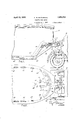
Figure 1 is a side elevation illustrating the improved trailer hitch in operative position between a vehicle and a semi-trailer;
Figure 2 is a plan thereof illustrating the hitch in normal operation;
Figure 3 is a plan thereof illustrating the hitch at the limit vof its first pivotal move- .ac-)menti y I Figure l is a plan thereof illustrating the hitch in a position in which bothv pivotal movements are brought into play;
Figure 5 is a detail illustrating the man- Ar. ner of making interlocking connection be- 'J tween the members of the'hitch; and
Figure 6 is a detail View illustrating a modified form of mounting for the hitch member on the driven vehicle. Y
Referring to the drawings, the numeral designates a driven vehicle suchas'a passenger coup, and the numeral 11 a semitrailer, for example, carrying a touring outfit including kitchen', sleeping quarters, etc. The improved hitch is indicated generally by the numeral 12. v
The member of hitch 12 connected'with Vvehicle 10 includes a base 13 mounted on the floor of vehicle 10, preferably on channels 15 secured to said floor. Swiveled onto base 13 is an element 16 formed withl lateral extensions 17, 17 riding on curved tracks 18, 18 on base 13, this construction providing the pivot on which the hitch first swings in operation, the pivotal action of which is limited in each direction to substantially forty-five" degrees ()v by means of stops 19, 19 on tracks 18 with which' extensions 17 will engage. Hinged on element 16 at 20', 20 is an upright 2O capable of limited swinging in a vertical plane to small angles with respect to the vertical, in which positions it is limited by abutments 21, 21 on element 16.'
In Figure 6 a modified form of mounting for upright 2O on the driven vehicle 11 is shown. In this form the base 13 has swiveled thereon the element 16 tracking thereon at 18', 1S. A second'element 20a has the upright hinged thereon at 2Ob for lateral rocking movement, this `movement being limited by abutments 20c, 20, element 20a-bei o' VVtrailer 11 at 11a is a link 26 supported by a curved track .i7 secured on the bottom portion llo the trailer and having an undercut rail 28 on which a supporting member 29, connected to link 26, rides to suspend the link 26 beneath the trailer.
To connect link 26 to upright 20, the ree end o1 the link is formed with an upper downwardly curved hook portion 30 Jor en gaging over the rounded protection 22e Sllz@ members 3l, 3l lor embracing portion 23 oi the upright 20 and lower upwardly curved prongs 33, 33 for engaging under shoulders 2e of upright 20. To secure the link 2G and 20 in locked relationship, a yoke 3ft is pivoted at 35 on a slide block 36 arranged in a slot 3? in link 26 and is adapted to be ,extended about upright 20 the slot 8T being directed at an angle as shown so to tighten the yoke onto upright 20 by downward operation of the slide block 36.` llo operate rthe slide block, a screw 38 is journaled in the link and threaded through the block and has an operating crank 39 thereon.
To the end that link 26 will normally be prevented from swinging on pivot 25, an extension 40 thereon is arranged to project between `two levers lll, el pivoted at L12, 42 on the bottom Loil the trailer andA yeldingly urged against the sides of extension e() by flexibleconnectors e3, 43 extended offer pulleys elli, ,4d and 45 45 and connecte-d to tensile springs 46, 46 secured to the chasis of the trailer at 4T, e7, action of the springs on levers ll beinglimited by stops at el 48.
In use, relative horizontal movement of the trailer li with respect to the driven vehicle l0 up, to ubstantially forty-live degrees in either direction from a position in alignment take-s place about the pivotal connection to the vehicle 'l0 at 1 6.. Further relative horizont-al movement to greater angles in either direction takes place about pivot 25. Springs 46 yielding under this action. Relative vertical movement longitudinally or in f lthe line of force between the vehicle and the trailer, as whengoincf over the crest of a hill or the like, takes place about the hinges 20 .O I' 202 and in the form oi' mounting shown in Figure 6, relative lateral rocking move'- ment takes place about pivot 2Gb. The manner of making or breaking the connection between vehicle and trailer will be readily Y understood, the parts being brought together element adapted to be swiveled to a driven vehicle for horizontal pivotal action, stops for limiting said pivotal action to a predej termined amount in either direction from normal alignment, an upright hinged onto said element for longitudinal Vertical pivotal action and also for lateral vertical rocking movement, an upwardly extending, rounded projection on the upper end of the upright, said upright being enlarged at its upper endl to define forwardly extending, upwardly curved shoulders thereon, a semitrailer having a link pivoted thereon for horizontal swinging movement, a'track on the trailer and means on the link engaging the track to suspend the free end of the link from the trailer, a downwardly curved, hooklike element on the free end of the link for engaging over said rounded projection, side elements on the free end Ot' the link for embracing the enlarged upper end of thc UP- right, upwardly curved, 'forwardly extending prongs on the bottom of the free end of the' lir for engaging under said shoulders on said Vupright, the lire-e end of the link having a slot thereinn a slide block in the slot,
a yoke pivoted on the slide block for einbrac- .ing the upper end of the upright, said block being adjustable to tighten'said yoke on said upright., an extension on the link, levers pivoted on the tra er, and yielding means urging the levers against opposite sides of the est-emision ncrmally tc Prcvcnt rivet-el, action or" the link with respect to the trailer but' adapted tc yield tc permit Such action accu said Swivclccl, element cngcecc .Said Stops- 2- A hitch tcl?- Scmtralcrs including' 21111 elementafleptccl tc bc SWvclccl t0 2 1 driven vehicle for horizontal pivotal, action, Stops for limiting said pivotal action to a predetermined. amount in either drcctcn from ncrmal alignment, an upright hinged onto said element for. longitudinal vertical pivotal action, an unwarcly extending rounded nrcicc tion on the upper end of the upright, said upric-ht being enlarged at its upper ccd tc; flac- .nc forwardly extending, upwardly curved Shoulders thereon, a Semi-trailcxi having c link pivoted thereon for horizontal swinging movement, a track on the trailer and means on the link engaging the track to suspend the free end of the link from the trailer, downwardly curved, hook-li e element on the :tree end of the link for engaging over said rounded projection, side elements on the free end ci the link for embracing; thc enlarged upper end of the upright, upwardly curved, for- Wardly extending prongs on the bottom ofthe free end of the link fory engagmg under said shoulders on said upright, the free end of the link having slot therein, a slide block in the slot, a, yoke pivoted on the slide block for embracing the upper end of the upright, ,saidV block being adjust-able to tighten said yoke on `said upright, an `extension on the link, and
yielding nieces clcctivc ceciicst erectile sides of the extension normally to prevent rirctal actcn el; @hcl-i111; with rccpcct tc thc trailer bet' eclartccl tc yicld tc permit such" action when said swiveled element engages said stops.
3. A hitch for semi-trailers including an element adapted to be swiveled to a driven vehicle for horizontal pivotall action, stops I link pivoted thereon for horizontal swinging movement, a track on the trailer and means on the link engaging the track to suspend the free end of the link from the trailer, interlocking means on the upper end-of the upright Y and the free end of the link for releasably locking these elements together, an extension on the link, and yielding Vmeans effective against opposite sides of the extension. normally to prevent pivotal action of the link with respect to the trailer but adapted to yield to permit such action when said swiveled element engages said stops.
4. A hitch for semi-trailers including an element adapted to be swiveled toa drivenV vehicle Jfor horizontal pivotal action, stops for limiting said pivotal action to a predetermined amount in either direction from normal alignment, an upright hinged onto said element for longitudinal vertical pivotal action, an upwardly extending, rounded proj ection on the upper end of the upright, said up-V right being enlarged at its upper end to define forwardly extending, upwardly curved shoulders thereon, a semi-trailer having a link pivoted thereon for horizontal swinging movement, interlocking means on the upper end of the upright and the tree end of the link for releasably locking these elements together, an extension on the link, and yielding means eHective against opposite sides of the extension normally to prevent pivotal action of the link with respect to the'trailer but adapted Y to yield to permit such action when said swiveled element engages said stops.
adapted to be connected to a driven vehicle, a member connected to the trailer, and means on each member for releasably interlocking it with the other, said means including anupwardly extending portion on the irst member formed with a rounded projection on its upper end and being enlarged adjacent said end to form Vforwardly extending upwardly curved shoulders, the second member having a forwardly extending portion formed with' an upper downwardly curved hook member for engaging ove-r said projection on the first member, side members for embracing the enlarged portion of the lirst member and upwardly curved prongs for engaging under the j upwardly curved, y prongs on the bottom ofthe free end of the flink' for'engaging under said shoulders on shoulders on said first member and means for 'securing said members 1n interlocked relationship.
6. -A ytrailer hitch including a member adapted to be connected to a driven vehicle,
a member Yconnected to the trailer,`and means on each `member for releasably interlocking it with tlierother saidmeans including an upwardly 'extending portion on the first-mem- V-ber formed with a rounded proj ectionv on its upper Aend and being enlarged adj acentV said end to vform forwardly extending upwardly curvedshoulders,the second member vhaving a forwardlyI extending portion formed' Awith an-upper downwardly curved hook member for engaging over said projection on thelirst Amember, upwardly curved prongs for engaging under the 'shoulders on said first member and means for securing said members in inter- 'locked relationship.
7. A hitch for semi-trailers including an element ladapted to be swiveled to a driven vehicle for horizontal pivotal action, stops for limiting `said pivotal action to a' predetermined amount in either direction from normal alignment, an upright hinged onto said element for longitudinal vertical-pivotal action, an upwardly extending, rounded projection on the upper end of the upright', said upright being enlarged at its upper end to define forwardly extending,up'wardly curved V'shoulders thereon, a semi-trailer having a link pivoted-'thereon for horizontal swinging movement, a downwardly curved, hook-like element on the free end of the link for engaging .over said rounded projection, side elements on the free end of the link for embracing 'the enlarged upper end of the upright, forwardly extending said upright, the free end of the link having a slot therein, a slide block in the slot', and a yoke pivoted on the slide block for embracing the upper end of the upright, said block being adjustable to tighten said yoke on .said upright.
'8. A hitch' for semi-trailers includingan element adapted to be swiveled to a driven ve- 5. A trailer hitch including a member fhicle for horizontal pivotal action', stops for limiting said pivotal action to a predetermined amoun't' in either direction `from normalalignment, an upright hinged onto said element for longitudinal vertical pivotal action, an upwardly extending, rounded projection on the upper end of vthe upright, said `upright Vbeing enlarged at its upper end to in the slot, and a yoke pivoted on the slide'VV block for embracing the upper end of the upright, said block being adjustable to tighten said yoke on said upright.
9. A h tch for semi-trailers including an element adapted to be swiveled to a driven c vehicle lfor horizontal-pivotal action, stops for limiting said pivotal action to a predetermined amount in either direction from normal` alignment, an upright hinged onto said element for longitudinal vertical pivotal action, an upwardly extending, rounded `projection on the upper end of the upright, said upright being enlarged at its upper end to deiine forwardly extending, upwardlycurved shoulders thereon, a semi-trailer having` a link pivoted thereon vfor horizontal swinging movement, a downwardly curved, hooklike elementen the free end of the link for engagingover said rounded projection, side elements on the free endof' the link for embracing the enlarged upper end of the upright, upwardly curved, forwardly extending prongs on the bottom of the free end of the link for engaging under'said'shoulders on saidupright, and means for releasably securing the upright and link in interlocking relationship. a
l0. A hitchv for semi-trailers including an element adapted to he swiveled to a driven `vehicle for horizontal pivotal action, stops for limiting said pivotal actionto a predetermined amount in either direction from normal alignment,` an upright hinged onto said element f or longitudinal vertical pivotal action, an upwardly extending, rounded projeotion on the upper end of the upright, said upright being enlarged at its upper end. to deii'ne forwardly extending, upwardly curvedl shoulders thereon, a semi-trailer havingV a link pivoted thereon for horizontal swinging movement, a` downwardly curved, .hook-like element on the free end of thel link forV engagingv over said rounded projection, ,and means for releasably secu-ring the upright, and link i-n interlockingrelationship.
l1, A semi-trailer hitchr` includinga member adapted to be attached to a driven vehicle, a` member attached tothe trailer, interlocking iformationson said members for releasably securing them together, one of sai-d members providing a socket and the other having` a `head engageahle in sai-d socket7 one of said members being Amounted for angularv movement with respect tothe other and said interlocking tormation permittingi-nterlocking of one toi-mation; with the. other only by such angular movement, and meansengageable with said socketl and head members to retaiin them in interlocked relationship.
ALFRED SCHLAEtir-Elli.V
Priority Applications (1)
| Application Number | Priority Date | Filing Date | Title |
|---|---|---|---|
| US171760A US1853701A (en) | 1927-03-01 | 1927-03-01 | Semitrailer hitch |
Applications Claiming Priority (1)
| Application Number | Priority Date | Filing Date | Title |
|---|---|---|---|
| US171760A US1853701A (en) | 1927-03-01 | 1927-03-01 | Semitrailer hitch |
Publications (1)
| Publication Number | Publication Date |
|---|---|
| US1853701A true US1853701A (en) | 1932-04-12 |
Family
ID=22625019
Family Applications (1)
| Application Number | Title | Priority Date | Filing Date |
|---|---|---|---|
| US171760A Expired - Lifetime US1853701A (en) | 1927-03-01 | 1927-03-01 | Semitrailer hitch |
Country Status (1)
| Country | Link |
|---|---|
| US (1) | US1853701A (en) |
Cited By (5)
| Publication number | Priority date | Publication date | Assignee | Title |
|---|---|---|---|---|
| US2925286A (en) * | 1957-05-03 | 1960-02-16 | Locomotion Engineering Inc | Fifth-wheel coupler for truck-trailer combination |
| US3302957A (en) * | 1965-02-05 | 1967-02-07 | Letourneau Westinghouse Compan | Anti-jack-knifing hitch assembly for tractor-trailers |
| US3498639A (en) * | 1967-12-14 | 1970-03-03 | Allis Chalmers Mfg Co | Vehicle tilt limit stop |
| US3525539A (en) * | 1968-11-08 | 1970-08-25 | Gen Motors Corp | Pull yoke assembly for articulated vehicle |
| US4420169A (en) * | 1982-04-30 | 1983-12-13 | Taylor Wayne A | Trailer hitch |
-
1927
- 1927-03-01 US US171760A patent/US1853701A/en not_active Expired - Lifetime
Cited By (5)
| Publication number | Priority date | Publication date | Assignee | Title |
|---|---|---|---|---|
| US2925286A (en) * | 1957-05-03 | 1960-02-16 | Locomotion Engineering Inc | Fifth-wheel coupler for truck-trailer combination |
| US3302957A (en) * | 1965-02-05 | 1967-02-07 | Letourneau Westinghouse Compan | Anti-jack-knifing hitch assembly for tractor-trailers |
| US3498639A (en) * | 1967-12-14 | 1970-03-03 | Allis Chalmers Mfg Co | Vehicle tilt limit stop |
| US3525539A (en) * | 1968-11-08 | 1970-08-25 | Gen Motors Corp | Pull yoke assembly for articulated vehicle |
| US4420169A (en) * | 1982-04-30 | 1983-12-13 | Taylor Wayne A | Trailer hitch |
Similar Documents
| Publication | Publication Date | Title |
|---|---|---|
| US3355043A (en) | Truck and body connection means | |
| US4106794A (en) | Multiple bar linkage towing system | |
| US2036344A (en) | Freight car for transporting vehicles | |
| US2743118A (en) | Trailer hitches | |
| US3659876A (en) | Trailer hitch | |
| US2460466A (en) | Trailer dolly | |
| US4060255A (en) | Wide range bumper mounted hitch | |
| US3542395A (en) | Trailer hitch | |
| US2808272A (en) | Car level and load adjusting device | |
| US1853701A (en) | Semitrailer hitch | |
| US2738206A (en) | Trailer hitch with vertically spaced connections | |
| US2410241A (en) | Riding dolly | |
| US2474296A (en) | Towing device for trailers | |
| US3152704A (en) | Vehicle towing device | |
| US2692146A (en) | Stabilized coupling mechanism for tractor-trailer vehicles | |
| US2714017A (en) | Anti-jackknife device for half-tandem of semi-trailer | |
| US3722917A (en) | Trailer hitch apparatus | |
| US3375946A (en) | Retractable hitch for tilting bed trucks | |
| US2531289A (en) | Trailer hitch | |
| US3764164A (en) | Converter dolly with slideable fifth wheel for use in combination with tractor-trailer rigs | |
| US2388923A (en) | Retractable vehicle support | |
| US1968623A (en) | Automotive vehicle | |
| US3722921A (en) | Tractor-trailer side tow construction | |
| US3394949A (en) | Trailer stabilzier | |
| US1255384A (en) | Means for transporting poles or the like. |