US1853658A - Door - Google Patents
Door Download PDFInfo
- Publication number
- US1853658A US1853658A US494323A US49432330A US1853658A US 1853658 A US1853658 A US 1853658A US 494323 A US494323 A US 494323A US 49432330 A US49432330 A US 49432330A US 1853658 A US1853658 A US 1853658A
- Authority
- US
- United States
- Prior art keywords
- door
- hinge
- branches
- spring
- notches
- Prior art date
- Legal status (The legal status is an assumption and is not a legal conclusion. Google has not performed a legal analysis and makes no representation as to the accuracy of the status listed.)
- Expired - Lifetime
Links
Images
Classifications
-
- B—PERFORMING OPERATIONS; TRANSPORTING
- B60—VEHICLES IN GENERAL
- B60H—ARRANGEMENTS OF HEATING, COOLING, VENTILATING OR OTHER AIR-TREATING DEVICES SPECIALLY ADAPTED FOR PASSENGER OR GOODS SPACES OF VEHICLES
- B60H1/00—Heating, cooling or ventilating [HVAC] devices
- B60H1/24—Devices purely for ventilating or where the heating or cooling is irrelevant
- B60H1/26—Ventilating openings in vehicle exterior; Ducts for conveying ventilating air
Definitions
- This invention relates to doors, and its principal object is to provide novel means for holding the door closed and in a plurality of selected open positions.
- the invention has particular reference to doors formed of struck up sheet metal and hinged to a sheet metal wall. Doors of this character are particularly useful for controlling ventilating openings in the hood, cowl and body portions of automobiles, although itis to be understood that the invention is not limited to such use.
- Another object is to provide spring urged means in a hinged door for holding the same closed and in a plurality of selected open positions, and composed of a minimum number of parts. Another object is to provide means for preventing the door from rattling.
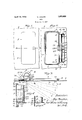
- Figure 1 is a side elevation of a fragment of a wall equipped with a door embodying a simple form of the present invention
- Fig.2 is a side elevation of the parts seen in Fig. 1, looking at the reverse side thereof;
- Fig. 3 is a detail horizontal section taken on the line 33 of Fig. 1;
- Fig. 4 is a detail vertical fragmental cross section taken on the line 4-4 of Figs. 2 and 3;
- Fig. 5 is a detail vertical fragmental cross section taken on the line 5-5 of Figs. 2 and 3.
- the reference character 6 designates a fragment of a wall having a door opening 7 therein of rectangular or other suitable configuration.
- the wall is composed of sheet metal, as shown, it is preferred to form it with an inset marginal flange 8 surrounding the door opening.
- the door is seen at 9, andwhen formed of sheet metal, as shown, is
- a knob or other handle 11 is usually provided to facilitate opening of the door.
- an upright flat bar 12 Secured to the inner face of the wall'6, as by spot welding or riveting it thereto, is an upright flat bar 12, the ends of which are bent at right angles to the main portion of the bar to provide ears 13 for receiving hinge pins 14.
- the portion of the flange 10 of the door adjacent the hinge connection with the wall is extended inwardly, as at 15, along an arc of acircle concentric withthehinge pins 14, and then curved back towards the hinge pins as at 16, thereby forming a substantially U-shaped connection between th door proper and the hinge.
- the top and bottom edge portions of the U-shaped part of the door are bent outtherefrom-to provide flanges 17 for the purpose of stiffening and strengthening the same, and said flanges are continued beyond the U- shapedpart to provide ears 18 that overlap the ears 13 of the bar 12 and receive the hinge pins 14. It will be noted that whenever the door is swung open, the arcuate flanged part 15 closes the gap between the hinged end of the door 9 and the wall 6.
- a U-shaped spring 19 is employed between. the bar 12 and the door 9..
- the bent part 20 of the spring 19 is held under a tongue 21 which is bentv up from the bar 12 and the two branches 22 of the spring diverge slightly and extend through an elongated vertical slot 28 formed in a flange 24 and also extend through horizontal slots 25 formed in the arcuate flanged portion 15 of the door.
- the bar 12 is formed with a lateral extension 26 which extends into the hollow of the U-shaped part 15, 16, of the door and is bent up to form the slotted flange 24.
- the upper edge of the upper slot 25 and the lower edge of the lower slot 25 are serrated or notched to provide two series of notches 27 which are 9 adapted to receive the two branches 22 of the spring 19.
- the tension of the spring is exerted in a direction to force the branches 22 thereof into oppositely disposed notches, and
- edges of the; notches are preferably rounded OK, so that when the door is moved to open or closed position, the spring branches may pass from one notch to another and thereby hold the door closed, or in any selected open position of adjustment.
- the slotted flange 24 prevents movement of the U-shaped spring in a direction transverse of the wall 6', although it permits-the branches thereof to swing toward andaway from each other. that by reason of the engagement of the branches 22 of the U-sha ed s rin 19 with.
- the spring serves to hold the door in any. position determined by the notches, and in Fig, 3, the door is illustrated in dotted: lines in the several open positions" in which it is held by the spring and other co-operating elements.
- the inclined side edges ofthe notches force the-two branches of the U-shaped spring out of the opposing notches, and-as-the next opposite notches come into register with the-two branches of the spring, said branches enter these notches and hold the door in the position determined by those notches.
- the door is positively held in any of the selected positions, and that there isno likelihood of any rattlingsound caused by vibration, and yet the door may beopened and closed with very little exertion.
- the invention is particularly adaptable foruse in automobiles, as, for instance, for controlling openingsinthe hood or cowl, in thebody portion, or-in other parts of an: automobile.
- a hinged doorhavingan'arcuate portion concentric with' the. hinge line of the door and connecting the doorwith the hinge portion, said arcuate portion being provided with a transversely extending serrated edge por tion, and a springanchored at one endand guided for movement in a direction at right angles to said serrated edge and urgedinto engagement with the serrations.
- a hinged door having'an arcuate portion concentric with respect t'o-the hinge line. and formed with a notched slot which extends transverselyto the plane ofthe door, and a spring anchored at one end and engaging in saidxnotched slot, said spring being guided to move in a line at right angles to said slotand urged into engagement with the notches thereof.
- a hinged door having an arcuate portion disposed concentric with-its hinge lineand formed with spaced slots extending trans It willbe. seen, therefore,
- a door formed with an arcuate flanged part terminating in hinge ears, a supporting bar for the door having outstanding ears hingedly connected with the ears of the door, a U-shapedspring'secured on said bar and having two branches engaging in notched slotsformed in said arcuate portion of'the door, and a guide member for guiding: the two branches of said spring tomove in lines extending between opposing notches.
- a supporting, bar formed with a lateral projection-ten minating; in a slotted flange, a door having an arcuate portion terminating inhingerears pivotally connected tosaidbar, said-arcuate portion being formed with'a pair of notched slots extending transversely to the plane of the door, a U-shaped spring secured to said bar and having its two branches extending through) the notched slots: of said: flange: and engaging in opposite notches therein,v and guiding means for guiding said two branches ofthe spring to move at right angles torsaid slots.
- a hinge comprisingtwo hingedtogeth'er members, one having an arcuate part concentrio with the hinge line thereofand-formed with a pair of edge notched slots andspring means having, two arms engaging in:
- a hinge comprising two members, one
Description
April 12, 1932. M. BRIISKIN 1,853,658
DOOR
Filed Nov. 8, 1930 Patented Apr. 12, 1932 UNITED STATES MAX BRISKIN, O13 CH ICAGO, ILLINOIS Application filed November 8,1930. Serial No. 494,323.
This invention relates to doors, and its principal object is to provide novel means for holding the door closed and in a plurality of selected open positions. The invention has particular reference to doors formed of struck up sheet metal and hinged to a sheet metal wall. Doors of this character are particularly useful for controlling ventilating openings in the hood, cowl and body portions of automobiles, although itis to be understood that the invention is not limited to such use.
Another object is to provide spring urged means in a hinged door for holding the same closed and in a plurality of selected open positions, and composed of a minimum number of parts. Another object is to provide means for preventing the door from rattling.
Other objects and advantages will appear in the course of this specification, and with all of said objects and advantages in view, this invention consists in the several novel features of construction, arrangement and combination of parts hereinafter fully set forth and claimed.
The invention is clearly illustrated in the drawingsaccompanying this specification in' which Figure 1 is a side elevation of a fragment of a wall equipped with a door embodying a simple form of the present invention;
Fig.2 is a side elevation of the parts seen in Fig. 1, looking at the reverse side thereof;
Fig. 3 is a detail horizontal section taken on the line 33 of Fig. 1;
Fig. 4 is a detail vertical fragmental cross section taken on the line 4-4 of Figs. 2 and 3; and
Fig. 5 is a detail vertical fragmental cross section taken on the line 5-5 of Figs. 2 and 3.
Referring to said drawings, which illustrate a simple embodiment of the invention, the reference character 6 designates a fragment of a wall having a door opening 7 therein of rectangular or other suitable configuration. When the wall is composed of sheet metal, as shown, it is preferred to form it with an inset marginal flange 8 surrounding the door opening. The door is seen at 9, andwhen formed of sheet metal, as shown, is
also formed with an inset marginal flange 10. A knob or other handle 11 is usually provided to facilitate opening of the door.
' Secured to the inner face of the wall'6, as by spot welding or riveting it thereto, is an upright flat bar 12, the ends of which are bent at right angles to the main portion of the bar to provide ears 13 for receiving hinge pins 14. The portion of the flange 10 of the door adjacent the hinge connection with the wall is extended inwardly, as at 15, along an arc of acircle concentric withthehinge pins 14, and then curved back towards the hinge pins as at 16, thereby forming a substantially U-shaped connection between th door proper and the hinge.
The top and bottom edge portions of the U-shaped part of the door are bent outtherefrom-to provide flanges 17 for the purpose of stiffening and strengthening the same, and said flanges are continued beyond the U- shapedpart to provide ears 18 that overlap the ears 13 of the bar 12 and receive the hinge pins 14. It will be noted that whenever the door is swung open, the arcuate flanged part 15 closes the gap between the hinged end of the door 9 and the wall 6.
For the purpose of holding the door closed, or in any of several selected open positions, a U-shaped spring 19 is employed between. the bar 12 and the door 9.. The bent part 20 of the spring 19 is held under a tongue 21 which is bentv up from the bar 12 and the two branches 22 of the spring diverge slightly and extend through an elongated vertical slot 28 formed in a flange 24 and also extend through horizontal slots 25 formed in the arcuate flanged portion 15 of the door.
The bar 12 is formed with a lateral extension 26 which extends into the hollow of the U-shaped part 15, 16, of the door and is bent up to form the slotted flange 24. The upper edge of the upper slot 25 and the lower edge of the lower slot 25 are serrated or notched to provide two series of notches 27 which are 9 adapted to receive the two branches 22 of the spring 19. The tension of the spring is exerted in a direction to force the branches 22 thereof into oppositely disposed notches, and
the edges of the; notches are preferably rounded OK, so that when the door is moved to open or closed position, the spring branches may pass from one notch to another and thereby hold the door closed, or in any selected open position of adjustment.
The slotted flange 24 prevents movement of the U-shaped spring in a direction transverse of the wall 6', although it permits-the branches thereof to swing toward andaway from each other. that by reason of the engagement of the branches 22 of the U-sha ed s rin 19 with.
P P a:
the oppositely disposed notches, the spring serves to hold the door in any. position determined by the notches, and in Fig, 3, the door is illustrated in dotted: lines in the several open positions" in which it is held by the spring and other co-operating elements.
hen the door'is opened, the inclined side edges ofthe notches force the-two branches of the U-shaped spring out of the opposing notches, and-as-the next opposite notches come into register with the-two branches of the spring, said branches enter these notches and hold the door in the position determined by those notches. It will be understoodfrom the above, thatthe door is positively held in any of the selected positions, and that there isno likelihood of any rattlingsound caused by vibration, and yet the door may beopened and closed with very little exertion. The inventionis particularly adaptable foruse in automobiles, as, for instance, for controlling openingsinthe hood or cowl, in thebody portion, or-in other parts of an: automobile.
More orless variation-o'f'the exact details of construction is possible'without departing from the spirit of this invention. I desire, therefore,- not tolimit myself to the exact form otthe construction shown anddescribed, but'intend; in the following claims, ttrpoint out all of the invention disclosed-herein.
I claim'as new, and desire to secure byLetters' Patent 1. A hinged doorhavingan'arcuate portion concentric with' the. hinge line of the door and connecting the doorwith the hinge portion, said arcuate portion being provided with a transversely extending serrated edge por tion, and a springanchored at one endand guided for movement in a direction at right angles to said serrated edge and urgedinto engagement with the serrations.
2. A hinged door having'an arcuate portion concentric with respect t'o-the hinge line. and formed with a notched slot which extends transverselyto the plane ofthe door, and a spring anchored at one end and engaging in saidxnotched slot, said spring being guided to move in a line at right angles to said slotand urged into engagement with the notches thereof.
3. A hinged door having an arcuate portion disposed concentric with-its hinge lineand formed with spaced slots extending trans It willbe. seen, therefore,
versely to the plane of the door, there being a series of notches formed in an edge of each slot and disposed opposite each other, a U- shaped spring anchored at its bent end and having its two branches urged into engagement in opposite notches of said slots, and a guide member for guiding the two branches of said spring to move in-lines between oppositely disposed notches.
4. A door formed with an arcuate flanged part terminating in hinge ears, a supporting bar for the door having outstanding ears hingedly connected with the ears of the door, a U-shapedspring'secured on said bar and having two branches engaging in notched slotsformed in said arcuate portion of'the door, and a guide member for guiding: the two branches of said spring tomove in lines extending between opposing notches.
5. The combination with a sheet metalfwall having a door opening therein, of: a: sheet metal door for closing said door opening and formed with an arcuate portionrterminating in hinge cars, a bar securedto-said wall and formed with hinge ears-pivotally secured to the hinge ears ofthe door, a. U shaped spring secured to said bar and having two branches guided to move in a direction parallel. with the wall and engaging in notched-transversely extending slots formed in said arcuate portionof'the door;
6.v The combination with a sheet metalwall having door opening therein, and a bar formed with ears on its ends. andsecured to the inner face of said wall, ofaihingedsheet metal door having a marginal flange entering said door opening, the flange adjacent the hinge. being extended. tov form an arcuate portion terminating in hinge ears pivotally connected to the hinge earsofthe bar, aUishaped springtsecured'to said bar and having its. two. branches guided to move. in a'plane parallel to said wall and extending through notched slots formed in said arcuate: flanged portion, said branches beingurged' intoop.- posing; notches of the notched slots.
7. Ina door, the combination ofa supporting, bar formed with a lateral projection-ten minating; in a slotted flange, a door having an arcuate portion terminating inhingerears pivotally connected tosaidbar, said-arcuate portion being formed with'a pair of notched slots extending transversely to the plane of the door, a U-shaped spring secured to said bar and having its two branches extending through) the notched slots: of said: flange: and engaging in opposite notches therein,v and guiding means for guiding said two branches ofthe spring to move at right angles torsaid slots.
8. A hinge comprisingtwo hingedtogeth'er members, one having an arcuate part concentrio with the hinge line thereofand-formed with a pair of edge notched slots andspring means having, two arms engaging in: the
notches of said slots and secured to the other hinged member against movement in a direction concentric with the arcuate slotted part of the first mentioned member.
9. A hinge comprising two members, one
having an arcuate part concentric with the hinge line of the hinge and terminating at its ends in hinge ears and the other member of the hinge having hinge ears co-operating with the hinge ears of the first mentioned member, said arcuate part being formed with an edge notched slot therein, and spring means on the other member of the hinge having an arm engaging in said notched slot and secured against movement in a direction concentric with said arcuate part. 7
MAX BRISKIN.
Priority Applications (1)
| Application Number | Priority Date | Filing Date | Title |
|---|---|---|---|
| US494323A US1853658A (en) | 1930-11-08 | 1930-11-08 | Door |
Applications Claiming Priority (1)
| Application Number | Priority Date | Filing Date | Title |
|---|---|---|---|
| US494323A US1853658A (en) | 1930-11-08 | 1930-11-08 | Door |
Publications (1)
| Publication Number | Publication Date |
|---|---|
| US1853658A true US1853658A (en) | 1932-04-12 |
Family
ID=23964004
Family Applications (1)
| Application Number | Title | Priority Date | Filing Date |
|---|---|---|---|
| US494323A Expired - Lifetime US1853658A (en) | 1930-11-08 | 1930-11-08 | Door |
Country Status (1)
| Country | Link |
|---|---|
| US (1) | US1853658A (en) |
Cited By (6)
| Publication number | Priority date | Publication date | Assignee | Title |
|---|---|---|---|---|
| US2707302A (en) * | 1949-06-11 | 1955-05-03 | Atwood Vacuum Machine Co | Automobile door hinge |
| US2726744A (en) * | 1951-07-25 | 1955-12-13 | Entpr Railway Equipment Co | Gondola type railway car convertible from closed to open end construction |
| US2894277A (en) * | 1953-11-18 | 1959-07-14 | Gen Motors Corp | Deck lid hinge with adjustable counterbalance |
| US3096538A (en) * | 1960-12-21 | 1963-07-09 | Gen Motors Corp | Closure hinge |
| US3153260A (en) * | 1961-01-11 | 1964-10-20 | Gen Motors Corp | Closure hinge |
| US4850142A (en) * | 1988-04-11 | 1989-07-25 | Paccar Inc | Articulating vent window assembly |
-
1930
- 1930-11-08 US US494323A patent/US1853658A/en not_active Expired - Lifetime
Cited By (6)
| Publication number | Priority date | Publication date | Assignee | Title |
|---|---|---|---|---|
| US2707302A (en) * | 1949-06-11 | 1955-05-03 | Atwood Vacuum Machine Co | Automobile door hinge |
| US2726744A (en) * | 1951-07-25 | 1955-12-13 | Entpr Railway Equipment Co | Gondola type railway car convertible from closed to open end construction |
| US2894277A (en) * | 1953-11-18 | 1959-07-14 | Gen Motors Corp | Deck lid hinge with adjustable counterbalance |
| US3096538A (en) * | 1960-12-21 | 1963-07-09 | Gen Motors Corp | Closure hinge |
| US3153260A (en) * | 1961-01-11 | 1964-10-20 | Gen Motors Corp | Closure hinge |
| US4850142A (en) * | 1988-04-11 | 1989-07-25 | Paccar Inc | Articulating vent window assembly |
Similar Documents
| Publication | Publication Date | Title |
|---|---|---|
| US1853658A (en) | Door | |
| US2372431A (en) | Hinge | |
| US2185214A (en) | Compensating hinge structure for automobile hoods or the like | |
| US3038196A (en) | Door hinge | |
| US479857A (en) | Range hot-closet door | |
| US2290219A (en) | Door closing device | |
| US3170455A (en) | Removable oven door and hinge assembly | |
| US1853659A (en) | Door | |
| US1497500A (en) | Fastener for doors and the like | |
| US2143704A (en) | Pivot door plate | |
| US2715540A (en) | Cam latch | |
| US2185212A (en) | Compensating hinge structure for automobile hoods or the like | |
| US1785568A (en) | Gas range | |
| US2295421A (en) | Door holder | |
| US2087777A (en) | Ventilating device for automobiles | |
| US2027833A (en) | Automobile door hinge | |
| US1989151A (en) | Hinge | |
| US1582784A (en) | Door-operating structure | |
| US2441600A (en) | Combined door-hinging, door-checking, and door-holding device | |
| US1706100A (en) | Window-latching device | |
| US1198939A (en) | Shutter. | |
| US1732870A (en) | Ventilator | |
| US1841187A (en) | Closure fastener | |
| US1866735A (en) | Cowl ventilator | |
| US1574340A (en) | Doorcheck |