US1853587A - Permanent wave baker - Google Patents
Permanent wave baker Download PDFInfo
- Publication number
- US1853587A US1853587A US485950A US48595030A US1853587A US 1853587 A US1853587 A US 1853587A US 485950 A US485950 A US 485950A US 48595030 A US48595030 A US 48595030A US 1853587 A US1853587 A US 1853587A
- Authority
- US
- United States
- Prior art keywords
- jaws
- levers
- jaw
- hair
- plate
- Prior art date
- Legal status (The legal status is an assumption and is not a legal conclusion. Google has not performed a legal analysis and makes no representation as to the accuracy of the status listed.)
- Expired - Lifetime
Links
- 208000027418 Wounds and injury Diseases 0.000 description 6
- 239000004020 conductor Substances 0.000 description 6
- 238000010438 heat treatment Methods 0.000 description 6
- 229910052751 metal Inorganic materials 0.000 description 5
- 239000002184 metal Substances 0.000 description 5
- 239000000463 material Substances 0.000 description 4
- 239000010445 mica Substances 0.000 description 4
- 229910052618 mica group Inorganic materials 0.000 description 4
- 238000005452 bending Methods 0.000 description 2
- 230000007775 late Effects 0.000 description 2
- 102100035683 Axin-2 Human genes 0.000 description 1
- 101700047552 Axin-2 Proteins 0.000 description 1
- 229920001875 Ebonite Polymers 0.000 description 1
- 230000004075 alteration Effects 0.000 description 1
- 229910052782 aluminium Inorganic materials 0.000 description 1
- XAGFODPZIPBFFR-UHFFFAOYSA-N aluminium Chemical group [Al] XAGFODPZIPBFFR-UHFFFAOYSA-N 0.000 description 1
- 238000010276 construction Methods 0.000 description 1
- 230000006378 damage Effects 0.000 description 1
- 210000003128 head Anatomy 0.000 description 1
- 208000014674 injury Diseases 0.000 description 1
- 230000037431 insertion Effects 0.000 description 1
- 238000003780 insertion Methods 0.000 description 1
- 210000004761 scalp Anatomy 0.000 description 1
Images
Classifications
-
- A—HUMAN NECESSITIES
- A45—HAND OR TRAVELLING ARTICLES
- A45D—HAIRDRESSING OR SHAVING EQUIPMENT; EQUIPMENT FOR COSMETICS OR COSMETIC TREATMENTS, e.g. FOR MANICURING OR PEDICURING
- A45D4/00—Separate devices designed for heating hair curlers or hair-wavers
- A45D4/08—Separate devices designed for heating hair curlers or hair-wavers for flat curling, e.g. with means for decreasing the heat
- A45D4/12—Separate devices designed for heating hair curlers or hair-wavers for flat curling, e.g. with means for decreasing the heat heated by electricity
Definitions
- This invention relates to hair curling devices, and has for an object the provision of a simple and yet .unusually eflicient device which is particularly adapted for, though not necessarily limited to, use in baking permanent waves.
- a more detailed object is to provide a permanent wave baking device, the jaws of which are ivoted with respect to the remainder of the evice, whereby they are permitted to conform themselves to the mandrel whereupon the hair bping curled is wound, and thus establish a nicer fit between the baking device and the mandrel.
- a further object is to provide a permanent wave bakin device as described, which is composed o a very few and simple parts, most of which may be manufactured economicall as die stampings, and which maybe assem led to operate form with only a minimum number of screws, bolts, nuts, and the like.
- Fig. 1 is a medial sectional view of a permanent wave baking device, incorporating the principles of the present invention, and shown in operative position with respect to the head of a patient whose hair is being curled.
- Fig. 2 is a plan view taken in the direction of the arrow 2 of Fig. 1, portions of the figure being broken away and shown in section to disclose the construction to better advanthe present invention comprises a pair of pivotally joined leversand a jaw carried by each lever. These jaws, each of which is provided with heating means, is pivotally joined to its associated lever, whereby it is permitted to conform itself to a mandrel with a wisp of hair wound thereupon, and thereby establish a larger area of contact between the aw and the hair being curled, as compared to previously existing devices intended for similar use, wherein the jaws are rigidly mounted no with res ect to the levers of the clamp.
- Each of the levers'i, 8 comprise a plate 9 which may conveniently be formed. by die stamping from a sheet of metal of suitable gauge.
- Each plate 9 comprises a straight section 11, to which a handle portion 12, formed preferably of hard rubber or its equivalent, is secured as by a plurality of screws 13 extendlng through suitable apertures in the straight portion 11 of the plate 9, and threaded into the inner face of the handle portion 12.
- Each of the handle portions 12 extends beyond the extreme outer end 14 of the associated plate 9, so as to materially inso crease the leverage which may be developed by squeezing the outer ends 16 of the handles 12 together; and in order to facilitate gripping the two handles 12 a depression 17 is formed in each, adjacent its outer end and in its outer face.
- Each of the plates 9 is also provided with an inclined portion 18 which slopes outwards and away from the pivot pin 19, whereby the two levers 7 and 8 are joined.
- This pin 19 extends loosely through four flanges 21, each of which is formed by bending a lateral edge of the straight portion 11 of a plate 9, substantially at right angles therewith, thus bringing the two flanges 21 of each plate into parallelism with each other.
- a suitable aperture 22 is formed in each of the flanges 21 to permit insertion of the pivot pin 19, whereby the two levers 7 and 8 are pivotally joined.
- a coil spring 23 encircles the pivot pin 19, and has one end pressing against each lever 7, 8 at a point between the outer end 16 thereof and the pivot pin 19. Hence, the outer ends 16 of the levers 7, 8 are continually urged apart, with the result that the inner ends 24 thereof are continually urged toward each other.
- Laterally extending flanges 26 are provided at each side of the inclined portion 18 of each plate 9, and these flanges are curled about axes extending transversely with respect to the associated plate 9, as best illustrated upon Fig. 4.
- the curled flanges 26 of each plate 9 are dis osed in axial alinement with each other, wit the result that they cooperate to form a pivot pin whereb a clamping jaw of the device may be joine pivotally thereto.
- Each of these aws 27,28 which are mounted upon the levers 7 8, respectively, comprises a front plate 29 w ich is arcuate about an axis which extends lon 'tudinally with re-- spect to the jaw, and a ack plate 31 which also is preferably arcuate.
- the back plate 31 is rigidly connected to the front plate 29 through the expedient of flan es 32 formed by bending the edges of the ront plate 29 backwards and reversely with respect to the remainder of the front plate 29.
- the parts are so arranged, however, that suflicient space is left between the' front and back plates 29 and 31, respectively, toaccommodate an electrical resistance element 33.
- each comprises a sheet of mica 36, or similar material, having a continuous wire 37 of suitable conductin material wound thereupon.
- the wires 3 of the two plates 36 are connected in series with each other b means of an insulated wire 38, and current is supplied to both by conductors 39 and 41 which lead to the opposite ends of the wires 37 of the two plates 36 of the jaws 27 and 28, respectively.
- Each of the electrical resistance elements 33 is operated from the front and back lates 29 and 31, respectively, of the assoclated jaw, by a sheet of mica 42 or equivalent insulating and noncombustible material, whereby the wire 37 of each jaw is positively kept out of contact with the metal of which the jaws are constructed.
- This metal preferably is aluminum, because of the lightness, relative cheapness, and high efficiency in heat conduction thereof.
- the wires 39 and 41 gain access to the heating elements 33 within the jaws by extending through the tubular flanges 26 (see Fig. 2) from which they are spaced by mica washers
- Each jaw 27, 28 is also provided with a lug 46 adjacent each end thereof.
- Each of these lugs is preferably formed separately, and comprises a suitably curved body portion 47, the lateral edges of which are also engaged behind the reversely bent flanges 32 which tions 48 of each jaw are in alinement with each other, the parts being so proportioned and arranged that the pivot pin formed by 'the curved lateral flanges 26 of one of the plates 9 is pivotally receivable within the raised portions 48 of one of the jaws.
- This manner of mounting the jaw upon the associated lever permits a material amount of pivotal movement therebetween, as indicated y the full and broken lines on Fig. 4.
- the jaws are arranged with the concave faces of the front lates 29 of the two opposed jaws 27 and 28 acing each other, thereby defining a substantially cylindrical space 49 therebetween.
- a ground wire 51 is attached, preferably by one of the screws 13, to one of the plates 9, and this wire extends between the two handles 12, preferably twisted with the conductors 39 and 41, whereby current is conducted to the heating elements 33, thereby preventin possibility, of injury to a patient should e ectrical connection be established between one of the conductors or the wire 37 of the resistance elements, and the metal of the clamp. Every precaution is taken, however, to prevent such short-circuits, by interposing mica sheets 52 between the units, which are preferably insulated, and the adjacent metal.
- the baking clamp 6 is intended to be used in conjunction with a suitable hair clamp 56 and mandrel 57.
- the clamp 56 comprises a pair of parallel jaws 58 having a rubber or other suitable resilient covering 59, and means (not shown) for pressing the jaws 58 toward each other, with a wisp of hair 61 clamped firmly therebetween.
- These jaws serve not only to prevent discomfort to the patient but also to protect the scalp 62 of the patient rom the heated jaws 27 and 28, between which the mandrel 57 is gripped, with the wisp of hair 61 wound thereupon.
- the conventional manner of forming a permanent wave is by applying heat and pressure to a wisp of hair wound in this manner upon a mandrel.
- the jaws are rigidly connected to their supporting levers, with the result that these jaws cannot conform themselves to the shape of the substantially cylindrical mass of hair wound upon the mandrel.
- a baking clamp for hair dressing comprising a pair of pivotally joined levers, a jaw pivoted to each of said levers, each jaw being free to pivot independently of the other jaw, and means for heating said jaws.
- a baking clamp for hair dressing comprising a pair of pivotally joined levers, a aw pivoted to each of said levers, each jaw being free to pivot independently of the other jaw, spring means urging said jaws toward each other, and means for heating said jaws.
- a baking clamp for hair dressing comrising a pa1r of ivotally joined levers, a aw pivoted to eac of said levers, each jaw being free to pivot independently of the other jaw, spring means urging said jaws toward each other, an electrical resistance associated with each of said jaws, and electrical conductors associated with said resistance elements.
- a baking clamp for hair dressing comprising a pair of pivotally joined levers, an arcuate jaw pivoted to each of said levers each jaw being free to pivot independently of the other jaw, the concave faces of said jaws facing each other, and means for heating said aws.
- J 5 A baking clamp for hair dressing, comrising a pa1r of pivotall joined levers, a aw pivoted to each of sai levers for movement about an axis extending lon 'tudinally with respect to the 'aw, each of said jaws being free to pivot in ependently of the other jaw and bein of arcu-ate, transverse cross section, an e ectrical resistance associated with each of said jaws, and electrical conductors associated with said resistance elements.
- a bakin clamp for hair dressing comprising a pa1r of pivotally joined levers, a jaw pivoted to each of said levers, each of said jaws comprising a concave front plate having its edges bentbackwards and reverse- 1y with respect to the plate, a back plate engaged by said reversely bent edges, a resistance element disposed between said resistance element and each of said plates, and a lug adjacent each end of the jaw and mounted on the back thereof, but being engaged by said reversely bent edges, means on each of said levers pivotally engaging the In of the associated jaw, and electrical con actors leading to said resistance elements.
- a bakin clamp for hair dres c rr prising a pan of pivetally jeinen jaw pivoted to each of said levers, each of said jaws comprising a concave front plate having its edges bent backwards and reversely with respect to the plate, a back plate engaged by said reversely bent edges, a resistance element disposed between said resistance element and each of said plates, and a ,lug adjacent each end of the jaw and mounted on the back thereof, but being engaged by said reversely bent edges, and each of said levers comprising a plate having lateral edges bent into parallelism adjacent one end.
Description
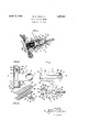
April 12, 1932. w. N. VANATTA PERMANENT WAVE BAKER Filed Oct. 2, 1950 FIG.2.
INVENTOR LLIS. N VANATTA JWW TTORNEYS- Patented Apr. 12, 1932v UNITED STATES WILLIS IN. YANATTA, OF ONTARIO, CALIFORNIA PERMANENT WAVE BAKER Application filed October 8, 1930. Serial No. 485,950.
This invention relates to hair curling devices, and has for an object the provision of a simple and yet .unusually eflicient device which is particularly adapted for, though not necessarily limited to, use in baking permanent waves.
A more detailed object is to provide a permanent wave baking device, the jaws of which are ivoted with respect to the remainder of the evice, whereby they are permitted to conform themselves to the mandrel whereupon the hair bping curled is wound, and thus establish a nicer fit between the baking device and the mandrel.
A further object is to provide a permanent wave bakin device as described, which is composed o a very few and simple parts, most of which may be manufactured economicall as die stampings, and which maybe assem led to operate form with only a minimum number of screws, bolts, nuts, and the like.
The invention possesses other objects and advantageous features, some of which, with those enumerated, will be set forth in the following description of the inventions particular embodiment which is illustrated in the drawings accompanying and forming a part of the specification.
Referring to the drawings:
Fig. 1 is a medial sectional view of a permanent wave baking device, incorporating the principles of the present invention, and shown in operative position with respect to the head of a patient whose hair is being curled.
Fig. 2 is a plan view taken in the direction of the arrow 2 of Fig. 1, portions of the figure being broken away and shown in section to disclose the construction to better advanthe present invention comprises a pair of pivotally joined leversand a jaw carried by each lever. These jaws, each of which is provided with heating means, is pivotally joined to its associated lever, whereby it is permitted to conform itself to a mandrel with a wisp of hair wound thereupon, and thereby establish a larger area of contact between the aw and the hair being curled, as compared to previously existing devices intended for similar use, wherein the jaws are rigidly mounted no with res ect to the levers of the clamp.
Speci 'cally describing that embodiment of the invention which at present appears to be most practical, I have provided a clamping device, indicated in its entirety at 6, and com- 05 pr sing a pair of levers 7 and 8 pivotally jipined intermediate their ends to each other.
ach of the levers'i, 8 comprise a plate 9 which may conveniently be formed. by die stamping from a sheet of metal of suitable gauge. 74) Each plate 9 comprises a straight section 11, to which a handle portion 12, formed preferably of hard rubber or its equivalent, is secured as by a plurality of screws 13 extendlng through suitable apertures in the straight portion 11 of the plate 9, and threaded into the inner face of the handle portion 12. Each of the handle portions 12 extends beyond the extreme outer end 14 of the associated plate 9, so as to materially inso crease the leverage which may be developed by squeezing the outer ends 16 of the handles 12 together; and in order to facilitate gripping the two handles 12 a depression 17 is formed in each, adjacent its outer end and in its outer face. Each of the plates 9 is also provided with an inclined portion 18 which slopes outwards and away from the pivot pin 19, whereby the two levers 7 and 8 are joined.
This pin 19 extends loosely through four flanges 21, each of which is formed by bending a lateral edge of the straight portion 11 of a plate 9, substantially at right angles therewith, thus bringing the two flanges 21 of each plate into parallelism with each other. A suitable aperture 22 is formed in each of the flanges 21 to permit insertion of the pivot pin 19, whereby the two levers 7 and 8 are pivotally joined. A coil spring 23 encircles the pivot pin 19, and has one end pressing against each lever 7, 8 at a point between the outer end 16 thereof and the pivot pin 19. Hence, the outer ends 16 of the levers 7, 8 are continually urged apart, with the result that the inner ends 24 thereof are continually urged toward each other.
Laterally extending flanges 26 are provided at each side of the inclined portion 18 of each plate 9, and these flanges are curled about axes extending transversely with respect to the associated plate 9, as best illustrated upon Fig. 4. The curled flanges 26 of each plate 9 are dis osed in axial alinement with each other, wit the result that they cooperate to form a pivot pin whereb a clamping jaw of the device may be joine pivotally thereto.
Each of these aws 27,28, which are mounted upon the levers 7 8, respectively, comprises a front plate 29 w ich is arcuate about an axis which extends lon 'tudinally with re-- spect to the jaw, and a ack plate 31 which also is preferably arcuate. The back plate 31 is rigidly connected to the front plate 29 through the expedient of flan es 32 formed by bending the edges of the ront plate 29 backwards and reversely with respect to the remainder of the front plate 29. The parts are so arranged, however, that suflicient space is left between the' front and back plates 29 and 31, respectively, toaccommodate an electrical resistance element 33.
These elements, which are illustrated in detail upon Fig. 5, each comprises a sheet of mica 36, or similar material, having a continuous wire 37 of suitable conductin material wound thereupon. The wires 3 of the two plates 36 are connected in series with each other b means of an insulated wire 38, and current is supplied to both by conductors 39 and 41 which lead to the opposite ends of the wires 37 of the two plates 36 of the jaws 27 and 28, respectively. Each of the electrical resistance elements 33 is operated from the front and back lates 29 and 31, respectively, of the assoclated jaw, by a sheet of mica 42 or equivalent insulating and noncombustible material, whereby the wire 37 of each jaw is positively kept out of contact with the metal of which the jaws are constructed. This metal preferably is aluminum, because of the lightness, relative cheapness, and high efficiency in heat conduction thereof. The wires 39 and 41 gain access to the heating elements 33 within the jaws by extending through the tubular flanges 26 (see Fig. 2) from which they are spaced by mica washers Each jaw 27, 28 is also provided with a lug 46 adjacent each end thereof. Each of these lugs is preferably formed separately, and comprises a suitably curved body portion 47, the lateral edges of which are also engaged behind the reversely bent flanges 32 which tions 48 of each jaw are in alinement with each other, the parts being so proportioned and arranged that the pivot pin formed by 'the curved lateral flanges 26 of one of the plates 9 is pivotally receivable within the raised portions 48 of one of the jaws. This manner of mounting the jaw upon the associated lever permits a material amount of pivotal movement therebetween, as indicated y the full and broken lines on Fig. 4. As is shown clearly upon that figure, the jaws are arranged with the concave faces of the front lates 29 of the two opposed jaws 27 and 28 acing each other, thereby defining a substantially cylindrical space 49 therebetween.
A ground wire 51 is attached, preferably by one of the screws 13, to one of the plates 9, and this wire extends between the two handles 12, preferably twisted with the conductors 39 and 41, whereby current is conducted to the heating elements 33, thereby preventin possibility, of injury to a patient should e ectrical connection be established between one of the conductors or the wire 37 of the resistance elements, and the metal of the clamp. Every precaution is taken, however, to prevent such short-circuits, by interposing mica sheets 52 between the units, which are preferably insulated, and the adjacent metal.
The baking clamp 6 is intended to be used in conjunction with a suitable hair clamp 56 and mandrel 57. The clamp 56 comprises a pair of parallel jaws 58 having a rubber or other suitable resilient covering 59, and means (not shown) for pressing the jaws 58 toward each other, with a wisp of hair 61 clamped firmly therebetween. These jaws serve not only to prevent discomfort to the patient but also to protect the scalp 62 of the patient rom the heated jaws 27 and 28, between which the mandrel 57 is gripped, with the wisp of hair 61 wound thereupon.
The conventional manner of forming a permanent wave is by applying heat and pressure to a wisp of hair wound in this manner upon a mandrel. However, in previously produced devices, for applying heat and pressure, the jaws are rigidly connected to their supporting levers, with the result that these jaws cannot conform themselves to the shape of the substantially cylindrical mass of hair wound upon the mandrel. Obviously, it is impossible to form the coil of hair upon the mandrel to precisely the same size and shape each time a coil is wound, with the result that the rigid jaws are not able in every instance to establish the greatest area of contact between themselves and the coil-of hair. This constitutes one of the improvements of my device over those previously produced, inasmuch as the jaws 27 and 28 may, by pivotal movement with respect to their supporting levers 7 and 8, respectively, seat themselves upon the coiled hair 61, so as to establish the greatest possible area of contact therebetween, thereby increasingthe efficiency and rapidity of operation of the baking clamp.
. It is to be understood that the details of the invention, as herein disclosed, are subject to alteration within the spirit or scope of the appended claims.
I claim: j 1. A baking clamp for hair dressing, comprising a pair of pivotally joined levers, a jaw pivoted to each of said levers, each jaw being free to pivot independently of the other jaw, and means for heating said jaws.
A baking clamp for hair dressing, comprising a pair of pivotally joined levers, a aw pivoted to each of said levers, each jaw being free to pivot independently of the other jaw, spring means urging said jaws toward each other, and means for heating said jaws.
3. A baking clamp for hair dressing, comrising a pa1r of ivotally joined levers, a aw pivoted to eac of said levers, each jaw being free to pivot independently of the other jaw, spring means urging said jaws toward each other, an electrical resistance associated with each of said jaws, and electrical conductors associated with said resistance elements.
4. A baking clamp for hair dressing, comprising a pair of pivotally joined levers, an arcuate jaw pivoted to each of said levers each jaw being free to pivot independently of the other jaw, the concave faces of said jaws facing each other, and means for heating said aws.
J 5 A baking clamp for hair dressing, comrising a pa1r of pivotall joined levers, a aw pivoted to each of sai levers for movement about an axis extending lon 'tudinally with respect to the 'aw, each of said jaws being free to pivot in ependently of the other jaw and bein of arcu-ate, transverse cross section, an e ectrical resistance associated with each of said jaws, and electrical conductors associated with said resistance elements.
6. A bakin clamp for hair dressing, comprising a pa1r of pivotally joined levers, a jaw pivoted to each of said levers, each of said jaws comprising a concave front plate having its edges bentbackwards and reverse- 1y with respect to the plate, a back plate engaged by said reversely bent edges, a resistance element disposed between said resistance element and each of said plates, and a lug adjacent each end of the jaw and mounted on the back thereof, but being engaged by said reversely bent edges, means on each of said levers pivotally engaging the In of the associated jaw, and electrical con actors leading to said resistance elements.
7. A bakin clamp for hair dres c rr prising a pan: of pivetally jeinen jaw pivoted to each of said levers, each of said jaws comprising a concave front plate having its edges bent backwards and reversely with respect to the plate, a back plate engaged by said reversely bent edges, a resistance element disposed between said resistance element and each of said plates, and a ,lug adjacent each end of the jaw and mounted on the back thereof, but being engaged by said reversely bent edges, and each of said levers comprising a plate having lateral edges bent into parallelism adjacent one end.
ing flanges of both of said levers, spring means interposed between said levers urging said jaws toward each other, and electrical conductors leading to said resistance elements.
In testimony whereof I have signed my name to this specification.
WILLIS N. VANATTA.
Priority Applications (1)
| Application Number | Priority Date | Filing Date | Title |
|---|---|---|---|
| US485950A US1853587A (en) | 1930-10-02 | 1930-10-02 | Permanent wave baker |
Applications Claiming Priority (1)
| Application Number | Priority Date | Filing Date | Title |
|---|---|---|---|
| US485950A US1853587A (en) | 1930-10-02 | 1930-10-02 | Permanent wave baker |
Publications (1)
| Publication Number | Publication Date |
|---|---|
| US1853587A true US1853587A (en) | 1932-04-12 |
Family
ID=23930039
Family Applications (1)
| Application Number | Title | Priority Date | Filing Date |
|---|---|---|---|
| US485950A Expired - Lifetime US1853587A (en) | 1930-10-02 | 1930-10-02 | Permanent wave baker |
Country Status (1)
| Country | Link |
|---|---|
| US (1) | US1853587A (en) |
-
1930
- 1930-10-02 US US485950A patent/US1853587A/en not_active Expired - Lifetime
Similar Documents
| Publication | Publication Date | Title |
|---|---|---|
| US20130146081A1 (en) | Hair styling apparatus | |
| US1853587A (en) | Permanent wave baker | |
| US2377953A (en) | Abrasive stick holder | |
| US2644142A (en) | Electric terminal clamp | |
| US1940704A (en) | Electric cable clamping plate | |
| US1639183A (en) | Pliers | |
| US2165552A (en) | Permanent waving apparatus | |
| US3102941A (en) | Hair conditioning implement | |
| US1987127A (en) | Means for connecting conductors and the like | |
| US1589818A (en) | Waesesf sitter | |
| US1528948A (en) | Electric heating device | |
| US2189865A (en) | Strain relieving device | |
| US2451102A (en) | Ruffle ironer | |
| US2258844A (en) | Device for straightening hair | |
| US2134869A (en) | Hair-waving heater | |
| US2155282A (en) | Hair waving device | |
| US1865655A (en) | Hair waver | |
| US1762792A (en) | Electric hair curler | |
| US1982767A (en) | Curl presser | |
| US1539898A (en) | Device for straightening hair | |
| US1357926A (en) | Binding-post for electric wires | |
| JPH0559643B2 (en) | ||
| US1593055A (en) | Device and process for straightening hair | |
| US1771584A (en) | Hair-waving equipment | |
| US1937599A (en) | Apparatus for waving hair |