US1853580A - Vehicle paekino indicator - Google Patents
Vehicle paekino indicator Download PDFInfo
- Publication number
- US1853580A US1853580A US1853580DA US1853580A US 1853580 A US1853580 A US 1853580A US 1853580D A US1853580D A US 1853580DA US 1853580 A US1853580 A US 1853580A
- Authority
- US
- United States
- Prior art keywords
- indicator
- vehicle
- parking
- hands
- time
- Prior art date
- Legal status (The legal status is an assumption and is not a legal conclusion. Google has not performed a legal analysis and makes no representation as to the accuracy of the status listed.)
- Expired - Lifetime
Links
- 239000011521 glass Substances 0.000 description 10
- 238000010276 construction Methods 0.000 description 4
- BFPSDSIWYFKGBC-UHFFFAOYSA-N Chlorotrianisene Chemical compound C1=CC(OC)=CC=C1C(Cl)=C(C=1C=CC(OC)=CC=1)C1=CC=C(OC)C=C1 BFPSDSIWYFKGBC-UHFFFAOYSA-N 0.000 description 2
- 230000000875 corresponding Effects 0.000 description 2
- 230000002452 interceptive Effects 0.000 description 2
- 238000004519 manufacturing process Methods 0.000 description 2
- ATJFFYVFTNAWJD-UHFFFAOYSA-N tin hydride Chemical compound [Sn] ATJFFYVFTNAWJD-UHFFFAOYSA-N 0.000 description 2
Images
Classifications
-
- G—PHYSICS
- G07—CHECKING-DEVICES
- G07B—TICKET-ISSUING APPARATUS; FARE-REGISTERING APPARATUS; FRANKING APPARATUS
- G07B15/00—Arrangements or apparatus for collecting fares, tolls or entrance fees at one or more control points
- G07B15/02—Arrangements or apparatus for collecting fares, tolls or entrance fees at one or more control points taking into account a variable factor such as distance or time, e.g. for passenger transport, parking systems or car rental systems
-
- A—HUMAN NECESSITIES
- A61—MEDICAL OR VETERINARY SCIENCE; HYGIENE
- A61J—CONTAINERS SPECIALLY ADAPTED FOR MEDICAL OR PHARMACEUTICAL PURPOSES; DEVICES OR METHODS SPECIALLY ADAPTED FOR BRINGING PHARMACEUTICAL PRODUCTS INTO PARTICULAR PHYSICAL OR ADMINISTERING FORMS; DEVICES FOR ADMINISTERING FOOD OR MEDICINES ORALLY; BABY COMFORTERS; DEVICES FOR RECEIVING SPITTLE
- A61J7/00—Devices for administering medicines orally, e.g. spoons; Pill counting devices; Arrangements for time indication or reminder for taking medicine
- A61J7/04—Arrangements for time indication or reminder for taking medicine, e.g. programmed dispensers
Definitions
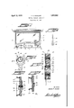
- VEHICLE PARKING INDICATOR Filed May 16, 1951 gmwntoi Ta/nas' E Jam/aw Patented Apr. 12, 1932 UNITED STATI-is rnonns H. sANDoW, or WILKESLBARRE, rmvNsYLvANIA .VEHICLE PARKING INDICATOR'A Application led May 16,
- This invention relates to a method and apparatus for indicating the length of time that a vehicle has been parked.
- the down town Aor business sections -thetime allowed for parking may be one hour, and in less lcongested ⁇ sections the time may be two-hours, Whereas in the residential districts the parking time may be unlimited.
- yGrreat diiiiculty has been experienced in enforcing the ⁇ parking regulations,"since many automobiles are parked within the restricted zone beyond the time allowed by law.
- One object ofthe :present invention therefore is to provide a parking indicator for attachment yto automobiles or other vehicles which Will indicate at a glance the time that a -vehicle has Vbeen parked.
- Another object of the present invention is to .provide a parking indicator for attachment yto automobiles which is adapted to be theriders therein.
- a furtherobject ofthis invention therefore isthe provision' of ⁇ a system of'timing vehicles parked Tin garages or other spaces whereicharges are made inaccordance with the time of parking in which an indicatormay .be vset 'by each automobile owner, andwhich may beqreadily attached to eachvehiclefto clearly show the time of parking when tlie' 75 ownerre-claims his automobile.
- l i A further ⁇ object of vthis* invention Yis the A' f provision of a system of timing and a parking indicator for use in said system .whereby ya V manually adjustableindicator may beset .3@ l
- Figure 3 is a vertical section onan enlarged scale taken through the indicatorot Figures" 1 and 2.
- v Y Y Figure 4- is a view of one of the indicator hands.
- Y v V Figure 5 is a sectional view of-another embodiment of the invention embodying a suction cup for attaching to a vehicle.
- Figure 6 is a sectional view of a single dial indicator embodying a suction cup.
- FIG. 1 one embodiment of my novel indicator is shownY in Figure 1 as attached lto the instrument panel of'an auto-mobile havingy an enclosed body.
- the instrument panel 1 is provided with the .usual instruments 2, and the corner brackets 3 for supporting the Windshield 4 and the top in the usual manner.
- the novel parking indicator 5 constituting the present embodiment is mounted on the instrument panel kadj acent ⁇ one end thereof and projects upwardly whereby the tace of the same may be clearly viewed through the windshield 4.
- my novel indicator embodies a supporting bracket 6 including a bottom strap having openings 7 therein forsecuring bolts, and having upwardly extending'divergent arms 8 to which are secured the indicating mechanism.
- the upper ends of arms 8 carry supporting .head 9 having a rectangular or circ-ular opening for providing a rigidy framework to which the indicating mechanism may be secured.
- front andV back members 12 and 13 Secured to the frame9 are the front andV back members 12 and 13 having suitable holes therein for Aalignment with corresponding holes in thehead 9 for the reception of locking vbolts 14.
- Each 'of 'themembers 12 and'13 is provided with a circular recess 15.
- TheH dial and hand'fsupportingbase 16 is secured against the faceof support 9 by member 13, the base 16 being apertured-for the recept-ion of bolts 14.
- -Member 16 has va central opening in Vwhich is positioned thev supporting members for the indicating hands of the parking device.
- a sleeve 17 has an external di- .aineterto have a'workingiit with the opening,
- Each end of the sleeve 17 has a boss 19 provided with a flat portion adapted for the reception of an indicating hand.
- the indicating hands are similar in construction, one hand being shown in Figure 4.
- the hand 32 has an opening23 in the hub 24 thereof, opening 23 being substantially circular with two straight sides for engagement with the flat portions of the bosses 19.
- Sleeve 17 has a plain unthreaded opening throughout its length.
- Tithin sleeve 17 is a second sleeve or bearing post 25.
- the two sleeves may be rotated with respect to one another.
- Sleeve 25 has flange 26 adjacent one end and is also provided with projecting bosses 27 having flattened portions thereon similar to bosses 19 of the-sleeve 17. lEach end of the sleeve 25 is threaded for the reception of screws 28.
- the sleeves 17 and 25 are assembled as shown in Figure 3.
- the sleeve 17 is rst positioned through the opening insupporting member 16 and then the two minute hands 32 and 33 are forced over the bosses 19.
- the inner sleeve 25 is slippedinto the sleeve 17 and the twohour hands 34 and 35 are cating dialsV 36 and 37 having numerals ar-y e. ranged thereon similar to the face lof a clock.
- dials are arranged with their iigures progressively increasing in opposite directions.
- the parking indicator is preferably located in a portion of. the automobile wherein one of the dials with its cooperating hands maybe clearly viewed from the exterior of the vehicle, and the otherV may be viewed from the interior'tliereof.
- One convenient and preferred location of the indicator is shown in Figure 1, wherein thel For example if the vehicle is parked at three oclock the hour hand is turned by handto the numeral 3, and theminutehand is turned to the y numeral 12asV shown on 1the drawings.
- Each operator of a vehicle may be required by municipal or city ordinances to indicate the exact time at which a vehicle is parked. Furthermore such ordinances may make it unlawful to set the indicator at any other than the actual time at which the vehicle was parked. VVith each vehicle equipped with these indicators and each indicator clearly showing the time that the vhicle was parked, obviously an officer could tell at a glance n whether the vehicle had been parked longer than allowed by law in the particular Zone. Thus one officer could cover much more territory than under the present system.
- novel parking indicator may be mounted in various other positions in the vehicle, the principle requireinent being that the hands are readily accessible for positioning by the operator of the vehicle and that the dials and hands are visible from the exterior thereof.
- a readily detachable mountingis shown wherein the indicator is provided on one face with a iiexible rubber suction cup 38 whereby it may be readily attached to the glass of the windshield of anautomobile or to a window thereof, either on the interior of the closed body or exterior of the body.
- the indicator is provided on one face with a iiexible rubber suction cup 38 whereby it may be readily attached to the glass of the windshield of anautomobile or to a window thereof, either on the interior of the closed body or exterior of the body.
- the form of invention shown in Figure 5 ⁇ wherein the parking indicator may be readily attached to an automobile is also useful where someone other than the operator of the vehicle attaches the parking device to the vehicle.
- various garages and open air parking places are provided in which vehicles may be park-ed.
- the charges for parking in these garages or parking spaces usually depends upon the length of time that the vehicle remains parked.
- the form'of invention shown in Figure 5 therefore'when a machine is driven into a privately owned parkingrspace, the attendant or the vehicle operator may manually attach by the suction cup 38 a parking indicator to the vehicle.
- the indicator may be mounted within the car and set correctly, and the automobile owner may then lockf the rdoors-of; the: cari whereby ⁇ the'indicatorE may not bere-set;
- the owner may then lockf the rdoors-of; the: cari whereby ⁇ the'indicatorE may not bere-set;
- the owner may then lockf the rdoors-of; the: cari whereby ⁇ the'indicatorE may not bere-set;
- the owner .returns therecan' fbe yno dispenser as. ⁇ to the time of parkingfsince'the-indicator could: not have-been tampered with.
- the indicatorf has beenshownt ina simplified form. whereinfthe rubber suction cup38is mounted on the rear facelof aablock;,39 lembodying; only onefdial 42., supporting two hands on the adj acentxface thereof.
- the two' indicating hands 43,:and mayl be: friction; f ally vmounted on a; center; post for manual; independent adjustment;
- This formo-f ther invention is particularly useful in parking spaces and garages or any iother use: wherein the necessity of viewing; the indicator from two directions isavoided'.
- 'A parking indicator comprising a sup porting member, two indicating dials thereon and facing in opposite directions, indicia on said dials representing hours Vand minutes, said supporting member having an opening therethrough Vconcentric with said dials, a bearing post passing through said ⁇ opening and having its ends projecting beyond the two dials, an indicating hand secured to each projecting end of said bearing post forsimultaneous rotation adjacent the two dials, a sleeve surrounding said'bearing post and having its ends projecting beyond the two dials',
- A. parking indicator'- for automobiles comprising a supporting member, twooppositely facing dials thereon having indicia representing time intervals, and indicating hands cooperating with each dial, said hands being. connected for simultaneous manual adjustment, andV a hollow vsuction cup on said supporting Vmember surrounding one dial and spaced beyond the dial whereby said indicatorlmay be readily attached to a glass panel of an automobile with one dial visible through the glass and the hollow suction cup.
- A12 .parking indicator for automobiles comprising a supporting member, two dials on opposite faces thereof having indicia representing hours and minutes, two hourvhands one cooperating with each ⁇ dial, two minute hands one cooperating witheach dial, a bear- -ing post projecting through said supporting member and having both hour hands secured theretofa sleeve surrounding said post and projecting through said member and having both minute hands secured thereto, and a hollow suction ⁇ cup secured to said supporting member and surrounding one dial whereby one set of hands maybe vmanually positioned to indicate the time a vehicle is parked and the suction cup'then securedto the inner sur- Y. 'face of the -windshield'of the automobile, one
Description
April 12, 1932. -rY H. SANDOW .1,853,580
VEHICLE PARKING INDICATOR Filed May 16, 1951 gmwntoi Ta/nas' E Jam/aw Patented Apr. 12, 1932 UNITED STATI-is rnonns H. sANDoW, or WILKESLBARRE, rmvNsYLvANIA .VEHICLE PARKING INDICATOR'A Application led May 16,
This invention relates to a method and apparatus for indicating the length of time that a vehicle has been parked.
Practically all cities and municipalitiestoday have various regulations restricting the length lof time that vehicles such asauto'- mobiles may lbe parked on the streets. InV most cities the time for parking varies in accordance with the locality. For example, in
the down town Aor business sections -thetime allowed for parking may be one hour, and in less lcongested `sections the time may be two-hours, Whereas in the residential districts the parking time may be unlimited. yGrreat diiiiculty has been experienced in enforcing the `parking regulations,"since many automobiles are parked within the restricted zone beyond the time allowed by law.
In orderfto apprehend these violators-of lthe 'zcity laws, various expedients have been-resorted to, -the most common requiring .thel
actual presence of an oficer ofthe'law `who will time the vehicle by noting they-time it .was first parked and if the parkingextends beyond the allowed period. To .effectively time the parked cars in a city inthe above manner Aobviously requires the services of' a great many officers. One object ofthe :present invention therefore is to provide a parking indicator for attachment yto automobiles or other vehicles which Will indicate at a glance the time that a -vehicle has Vbeen parked.
Another object of the present invention is to .provide a parking indicator for attachment yto automobiles which is adapted to be theriders therein.
1931".-A serial No. 537,962".v
construction and cheap to manufacture and which maybe readily installed in an accessible position without interfering with vthe operating partsv of the vehicle nor with thevievv of In many congestedl localities garagesor open lots are utilized lasparking spaces'for automobiles, the ownersof the garages or lots charging the'operators ofthe automobiles in accordance with the time thatthe Vehicles'are '65 parked. Disputes frequently varise between theowner'sof automobilesand the operators ofthesegarages or lots as tothe parking time. Alsotor correctly time amultiplicity of vehicles which renter at dierent times and '65 leave at vdierent times now requires a written record for each vehicle.
A furtherobject ofthis invention therefore isthe provision' of `a system of'timing vehicles parked Tin garages or other spaces whereicharges are made inaccordance with the time of parking in which an indicatormay .be vset 'by each automobile owner, andwhich may beqreadily attached to eachvehiclefto clearly show the time of parking when tlie' 75 ownerre-claims his automobile. l i A further `object of vthis* invention Yis the A' f provision of a system of timing and a parking indicator for use in said system .whereby ya V manually adjustableindicator may beset .3@ l
by or in the presence of Ethe ,automobile r owner and then locked inthe Vclosed body of a parked Vcarlby the owner thereof'so that it ymay not rhe movedimtil the `owner opensthe car, the clasped 'time then can be easily calculated.v
Afurther object'of this .inventionis to prof videa simple and cheap indicatorhaving a clock `face and manually .movable A.handsand including a suction cup `to attach it to an auto- 99 mobile forzusein garages and'parking spaces V whereby one. indicator may be `manually set g and attachedto'each car as .it is parked, *andV the parking. timeV maybe readily computed-V when the' car owner re-claims vhiscar.` V95 .1A further objectof this linvention is the provision of a vsystem of .timing parked vef hicles whereby anaccurateandreadily available timing `record is f easily keptfor eachy vehiclewithout -requiring=written vrecords {o ffffltwA the time of entering and leaving the parking s ace.
pThese and other objects' of the invention will be apparent from the following description and the appended claims when taken in conjunction with the accompanying drawings wherein Y Figure lis a view of one embodiment of this invention attached to an enclosed automobile and viewed from the interior thereof. Figure 2 is an elevation of the'opposite face of the indicator shown in Figure 1 on a slightly larger scale. f
Figure 3 is a vertical section onan enlarged scale taken through the indicatorot Figures" 1 and 2.- v Y Y Figure 4-is a view of one of the indicator hands. Y v V Figure 5 is a sectional view of-another embodiment of the invention embodying a suction cup for attaching to a vehicle. Y f
Figure 6 is a sectional view of a single dial indicator embodying a suction cup.
Referring to t-lie drawings wherein like reference characters indicate like parts, one embodiment of my novel indicator is shownY in Figure 1 as attached lto the instrument panel of'an auto-mobile havingy an enclosed body. The instrument panel 1 is provided with the .usual instruments 2, and the corner brackets 3 for supporting the Windshield 4 and the top in the usual manner.V The novel parking indicator 5 constituting the present embodiment is mounted on the instrument panel kadj acent `one end thereof and projects upwardly whereby the tace of the same may be clearly viewed through the windshield 4.
vAls indicated more clearly in Figures 2 and 3, my novel indicator embodies a supporting bracket 6 including a bottom strap having openings 7 therein forsecuring bolts, and having upwardly extending'divergent arms 8 to which are secured the indicating mechanism. The upper ends of arms 8 carry supporting .head 9 having a rectangular or circ-ular opening for providing a rigidy framework to which the indicating mechanism may be secured.`
Secured to the frame9 are the front andV back members 12 and 13 having suitable holes therein for Aalignment with corresponding holes in thehead 9 for the reception of locking vbolts 14. The two members 12 and 13.
have the bolt holes enlarged at opposite ends whereby the heads of they bolts and the nuts are positioned below the surface of members 12 and 13. Each 'of 'themembers 12 and'13 is provided witha circular recess 15. TheH dial and hand'fsupportingbase 16 is secured against the faceof support 9 by member 13, the base 16 being apertured-for the recept-ion of bolts 14. -Member 16 has va central opening in Vwhich is positioned thev supporting members for the indicating hands of the parking device. A sleeve 17 has an external di- .aineterto have a'workingiit with the opening,
'in the supporting member 16 and is provided with a flange 18 adjacent one end thereot.
Each end of the sleeve 17 has a boss 19 provided with a flat portion adapted for the reception of an indicating hand. The indicating hands are similar in construction, one hand being shown in Figure 4. As illustrated, the hand 32 has an opening23 in the hub 24 thereof, opening 23 being substantially circular with two straight sides for engagement with the flat portions of the bosses 19. Sleeve 17 has a plain unthreaded opening throughout its length.
Tithin sleeve 17 is a second sleeve or bearing post 25. The two sleeves may be rotated with respect to one another. Sleeve 25 has flange 26 adjacent one end and is also provided with projecting bosses 27 having flattened portions thereon similar to bosses 19 of the-sleeve 17. lEach end of the sleeve 25 is threaded for the reception of screws 28.
flattened surfaces of the bosses 19 andl the' parallel edges of the openings 23 in the hands cooperate to prevent slipping of the hands and frictional engagement of the parts is sucient to retain the hands in position. VThenV the inner sleeve 25 is slippedinto the sleeve 17 and the twohour hands 34 and 35 are cating dialsV 36 and 37 having numerals ar-y e. ranged thereon similar to the face lof a clock.
However it will be noted from Figures 1 and 2 that the dials are arranged with their iigures progressively increasing in opposite directions.
.As indicated in Figure 1, the parking indicator is preferably located in a portion of. the automobile wherein one of the dials with its cooperating hands maybe clearly viewed from the exterior of the vehicle, and the otherV may be viewed from the interior'tliereof. One convenient and preferred location of the indicator is shown in Figure 1, wherein thel For example if the vehicle is parked at three oclock the hour hand is turned by handto the numeral 3, and theminutehand is turned to the y numeral 12asV shown on 1the drawings. Ro-
iig
tation of the'liour hand 34 causes simultaneous f rotation of the inner sleeve 25 carrying with 2^ .it the opposite hour handV 35. Similarly rotation of the minute hand 32 causes rotation i kof the outer sleeve 17 thus rotating` the opposite minute hand 33. The hands are thus simultaneously set on both dials 36 and 37 to clearly indicate to persons within and outside the automobile the-time at which it was parked.
Each operator of a vehicle may be required by municipal or city ordinances to indicate the exact time at which a vehicle is parked. Furthermore such ordinances may make it unlawful to set the indicator at any other than the actual time at which the vehicle was parked. VVith each vehicle equipped with these indicators and each indicator clearly showing the time that the vhicle was parked, obviously an officer could tell at a glance n whether the vehicle had been parked longer than allowed by law in the particular Zone. Thus one officer could cover much more territory than under the present system.
It will be obvious that the novel parking indicator may be mounted in various other positions in the vehicle, the principle requireinent being that the hands are readily accessible for positioning by the operator of the vehicle and that the dials and hands are visible from the exterior thereof.
In the embodiment illustrated in Figure 5, a readily detachable mountingis shown, wherein the indicator is provided on one face with a iiexible rubber suction cup 38 whereby it may be readily attached to the glass of the windshield of anautomobile or to a window thereof, either on the interior of the closed body or exterior of the body. In
either mounting the dial and hands within the suction cup are clearly visible through the cup and the glass.
The form of invention shown in Figure 5` wherein the parking indicator may be readily attached to an automobile is also useful where someone other than the operator of the vehicle attaches the parking device to the vehicle. For example in various congested localities such as the business sections i,of the'city, various garages and open air parking places are provided in which vehicles may be park-ed. The charges for parking in these garages or parking spaces usually depends upon the length of time that the vehicle remains parked. With the form'of invention shown in Figure 5 therefore'when a machine is driven into a privately owned parkingrspace, the attendant or the vehicle operator may manually attach by the suction cup 38 a parking indicator to the vehicle. He will then set the hands to indicate the actual time of parking, and when the operator returns the elapsed time .during which the vehicle has been parked will be readily ascertained from the set parking indicator hand and the time. Thus the correct charges for the parking of the vehicle may be simply computed. In the case of closed automobiles, the indicator may be mounted within the car and set correctly, and the automobile owner may then lockf the rdoors-of; the: cari whereby` the'indicatorE may not bere-set; Thus when'. the owner .returns therecan' fbe yno :dispute as.` to the time of parkingfsince'the-indicator could: not have-been tampered with.,
In .the form* of'. invention shown in Figure 6 the indicatorfhas beenshownt ina simplified form. whereinfthe rubber suction cup38is mounted on the rear facelof aablock;,39 lembodying; only onefdial 42., supporting two hands on the adj acentxface thereof. The two' indicating hands 43,:and mayl be: friction; f ally vmounted on a; center; post for manual; independent adjustment; This formo-f ther inventionis particularly useful in parking spaces and garages or any iother use: wherein the necessity of viewing; the indicator from two directions isavoided'. yThe formg-ofim Y vention shown finFigure maybe veryxcheapv ly manufactured and sold toy the opere ators of garages forparkingspaces,for ready attachmentto a vehicleas it ispa'rked. When the owner. reclaims. hisinachinel the` actualvv timeof parking is. easily'computed foreachv ear without the necessity 'off keepingy books or records. It willbe understood that the em#4 bodiment. shown in Figure yzcan also ybeset and then locked ,within an= automobile, ythus avoiding: all tpossible disputes'.4 asv tothe indicator having been movedduring the absencel ofthe operatorof the automobile, as described in connection withFigure 5.A l
It will be understood that mynovel systemf ofr timing the parking; of ,vehicles is not limited to the speciic..` embodimentsv shown: Othermodes of attaching the indicators to .ve-y hicles maybe used and'fa-ll within the purview of the invention.-` l i The invention;mayr be embodied :in other' specific forms without. departing froml the'A spirit or.4 essential characteristics thereof. The present* embodiment yis therefore to 2 be considered in allf respects as lillustrative and r notfrestrictive, the scope of the'finvention beingv indicatedfbythe appended claimsrather than Y lofi which come within the meaningfandrangeof'., equivalency of thefclaimsare therefore intended to be embraced'thereiin WhatvI claim and desire to secure by U. S; Letters Patent is i j 1. 'A parking indicator comprising a sup porting member, two indicating dials thereon and facing in opposite directions, indicia on said dials representing hours Vand minutes, said supporting member having an opening therethrough Vconcentric with said dials, a bearing post passing through said` opening and having its ends projecting beyond the two dials, an indicating hand secured to each projecting end of said bearing post forsimultaneous rotation adjacent the two dials, a sleeve surrounding said'bearing post and having its ends projecting beyond the two dials',
'an indicating hand secured to each projectingv endl of f said :sleeve for simultaneous rotation adjacent the two dials, and means for ysecuring said Vindicator to anl automobile with one dial visible from a distance.
2. The invention as defined in claim 1 wherein the projecting'ends of said bearing post and sleeve have flat surfaces thereon, and said hands have similar shaped openings engageable'over said ends.
3. The 'invention as defined in claim 1 wherein the means for securing the indicator to an automobile comprises a depending bracket, and means for securing said bracket to the instrument panel of the automobile :with one dial of said indicator visible through the windshield thereof. Y
zoV
V4. A. parking indicator'- for automobiles comprising a supporting member, twooppositely facing dials thereon having indicia representing time intervals, and indicating hands cooperating with each dial, said hands being. connected for simultaneous manual adjustment, andV a hollow vsuction cup on said supporting Vmember surrounding one dial and spaced beyond the dial whereby said indicatorlmay be readily attached to a glass panel of an automobile with one dial visible through the glass and the hollow suction cup.
`45. f A12 .parking indicator for automobiles comprising a supporting member, two dials on opposite faces thereof having indicia representing hours and minutes, two hourvhands one cooperating with each` dial, two minute hands one cooperating witheach dial, a bear- -ing post projecting through said supporting member and having both hour hands secured theretofa sleeve surrounding said post and projecting through said member and having both minute hands secured thereto, and a hollow suction `cup secured to said supporting member and surrounding one dial whereby one set of hands maybe vmanually positioned to indicate the time a vehicle is parked and the suction cup'then securedto the inner sur- Y. 'face of the -windshield'of the automobile, one
dial and hands being visible through the glass and the .hollowr cup. p. Y n In testimony whereof I'aihx my signature.
TrioMA'sH. sANDow. .j Y
Publications (1)
| Publication Number | Publication Date |
|---|---|
| US1853580A true US1853580A (en) | 1932-04-12 |
Family
ID=3423653
Family Applications (1)
| Application Number | Title | Priority Date | Filing Date |
|---|---|---|---|
| US1853580D Expired - Lifetime US1853580A (en) | Vehicle paekino indicator |
Country Status (1)
| Country | Link |
|---|---|
| US (1) | US1853580A (en) |
Cited By (2)
| Publication number | Priority date | Publication date | Assignee | Title |
|---|---|---|---|---|
| US2870735A (en) * | 1959-01-27 | Permit system for parking automobiles | ||
| US3104646A (en) * | 1963-09-24 | Time-setting device |
-
0
- US US1853580D patent/US1853580A/en not_active Expired - Lifetime
Cited By (2)
| Publication number | Priority date | Publication date | Assignee | Title |
|---|---|---|---|---|
| US2870735A (en) * | 1959-01-27 | Permit system for parking automobiles | ||
| US3104646A (en) * | 1963-09-24 | Time-setting device |
Similar Documents
| Publication | Publication Date | Title |
|---|---|---|
| KLAUBER et al. | The epidemiology of head injury: a prospective study of an entire community—San Diego County, California, 1978 | |
| US1853580A (en) | Vehicle paekino indicator | |
| US1752071A (en) | Means for regulating the use of street parking space | |
| US2870735A (en) | Permit system for parking automobiles | |
| US222597A (en) | Improvement in letter-box indicators | |
| US1727569A (en) | Oil-change indicator | |
| CN203345024U (en) | Automotive steering dial gauge | |
| US6380867B1 (en) | Traffic light sequence indication system | |
| US1004097A (en) | Program-clock. | |
| US1872838A (en) | Indicating device | |
| US1489408A (en) | Vehicle rear lamp and signaler | |
| Ackerly et al. | A nnouncements | |
| US726547A (en) | Odometer. | |
| JP3129763U (en) | Outside display aid | |
| US2173326A (en) | Coin operated time indicating device | |
| US1096670A (en) | Automobile number-plate. | |
| SU5530A1 (en) | Adaptation to the door to indicate the location of the person occupying the room, and the time of his return | |
| US177900A (en) | Improvement in fare controllers and indicators | |
| US1612407A (en) | Road meter | |
| US1276889A (en) | Street-car indicator. | |
| US2045822A (en) | Travel guide | |
| US1040345A (en) | Combined road-map and odometer. | |
| US1476580A (en) | License plate | |
| US1404868A (en) | Vehicle license sign | |
| US804087A (en) | Train-order indicator. |