US1853576A - Semitrailer - Google Patents
Semitrailer Download PDFInfo
- Publication number
- US1853576A US1853576A US481665A US48166530A US1853576A US 1853576 A US1853576 A US 1853576A US 481665 A US481665 A US 481665A US 48166530 A US48166530 A US 48166530A US 1853576 A US1853576 A US 1853576A
- Authority
- US
- United States
- Prior art keywords
- trailer
- cylinder
- valve
- truck
- pressure
- Prior art date
- Legal status (The legal status is an assumption and is not a legal conclusion. Google has not performed a legal analysis and makes no representation as to the accuracy of the status listed.)
- Expired - Lifetime
Links
Images
Classifications
-
- B—PERFORMING OPERATIONS; TRANSPORTING
- B60—VEHICLES IN GENERAL
- B60D—VEHICLE CONNECTIONS
- B60D1/00—Traction couplings; Hitches; Draw-gear; Towing devices
- B60D1/58—Auxiliary devices
- B60D1/66—Props
-
- B—PERFORMING OPERATIONS; TRANSPORTING
- B60—VEHICLES IN GENERAL
- B60S—SERVICING, CLEANING, REPAIRING, SUPPORTING, LIFTING, OR MANOEUVRING OF VEHICLES, NOT OTHERWISE PROVIDED FOR
- B60S9/00—Ground-engaging vehicle fittings for supporting, lifting, or manoeuvring the vehicle, wholly or in part, e.g. built-in jacks
- B60S9/14—Ground-engaging vehicle fittings for supporting, lifting, or manoeuvring the vehicle, wholly or in part, e.g. built-in jacks for both lifting and manoeuvring
- B60S9/16—Ground-engaging vehicle fittings for supporting, lifting, or manoeuvring the vehicle, wholly or in part, e.g. built-in jacks for both lifting and manoeuvring for operating only on one end of vehicle
- B60S9/20—Ground-engaging vehicle fittings for supporting, lifting, or manoeuvring the vehicle, wholly or in part, e.g. built-in jacks for both lifting and manoeuvring for operating only on one end of vehicle with fluid-pressure lift
Definitions
- This invention relates to improvements in semi-trailers and is particularly concerned with a front end carriage for supporting the front end of the trailer body when the trailer is unattached to a truck or other tractor means and for retaining the trailer body in the normal horizontal position for loading and unloading.
- the usual front end supports comprise pivotal legs and small wheels mounted on the lower ends thereof. Most, of these supports are operated manually through worm gears and cranks or through hydraulic pistons operable consequent upon the relative movement between the trailer and automotive truck. Since the present types of supports require manual operation by the operator of thetruck much inconvenience and loss of time results from their operation especially where several trailers are connected to form a train, as each trailer requires individual attention.
- My invention contemplates an operating mechanism for such front end supports which is simple and effective in operation, economical to manufacture and easy to install, and which may be operated either at the trailer or from the driving seat of the truck.
- Another advantage of my operating mechanism is that it is positive in action, both forlifting and lowering the front end support of the trailer, and is of sufficient strength to lift the front end of-the trailer higher than its normal position on the truck, even under comparatively heavy loads.
- Another advantage and object of my invention is that the supports of any number of trailers forming a train may be operated concurrently and easily, and the supports may be held firmly in. operating or idle position.
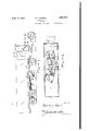
- Fig. l is a side elevation of a truck and trailer embodying my invention.
- Fig. 2 is a partial plan view of the trailer illustrated in Fig. 1.
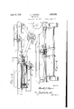
- Fig. 3 is an enlarged longitudinal sectional View of a portion of the trailer illustrated in Figs. 1 and 2, showing my invention in greater detail.
- Fig. 4 is an enlarged cross sectional view gaken on a plane indicated by the line 4-4 of
- my invention in eludes two or more transversely spaced legs 1 pivotally mounted at one end in brackets 2 onlongitudinal frame members 4 of the trailer.
- an axle 5 carrying a supporting wheel 6, which is adapted to swing in an are about the pivot point of the leg.
- Pivotally secured to each of the legs 1, for instance, to the axle 5 is an operating arm or leveri8.
- the other end of each of the levers is pivoted on a trunnion or cross shaft 9 on the body 10 of a carriage.
- the carriage is slidable longitudinally of the trailer along a track 11.
- this carriagei may include a body 10 provided with lugs 12 and 14 which engage tracks rigidly secured to the trailer frame. Rollers, such as 16 and 18, may be provided to engage the underside of the track to render operation of the carriage free and easy.
- An economical track may comprise a longitudinally extending I-beam 20 secured by its ends or otherwise to the trailer frame, and having its lower flanges machined for a sliding fit with the lugs 12 and 14 respectively.
- the wheel 6 In the extreme forward position of the carriage 10, the wheel 6 is advanced far enough to position its axis somewhat forward of the pivotal connection of the leg 1 in the bracket 2, so that the weight of the trailer tends to force the wheel forward and draw the carriage more tightly against a suitconnecting the trailer with a compressor and ed within the cylinder 30 is a re'ciprocablepiston 32 provided with a piston rod 34 extending outside of the cylinder, the piston rod passage being sealed bya suitable packing, as indicated at 36. As illustrated, -I
- I provide a conduit or air line 40 which communicates with a main feed line 41 leading from a compressor 38 or a compressed air tank on the truck.
- the conduit .40 opens'into a valve body 42 which communicates with conduits 44 and 46.
- the conduit 44 provides the passageway into the cylinder 36 on one side of passageway on the other side. These conduits preferably open into the cylinder at the ends, as illustrated.
- a simple and effective valve may include a plug 48 provided with passageways 49.
- valve body diametrically opposite to the opening of the conduit 40 is a small opening or bleeder 52.
- valve 42 As positioned on the trailer. This is especially desirable vwith trailers which are equipped with air brakes, as in such cases, each trailer is provided, with an air pressure line, 'fitted at each end with flexible operated concurrently without necessitating the driver leaving the seat of the truck.
- each of the conduits 44 and 46 may be tapped into separate main feed lines
- each main feed line should be provided at each end with flexible couplings so that it may be connected with corresponding lines on adjacent trailers in the train, the unconnected end of the lines of the last trailer being sealed.
- each main feed line would act to deliver pressure to all of the cylinders when the valve was in one position and would act as a discharge line to the valve bleeder .52 when. the positionof the valve was reversed.
- a tractor and trailer combination supporting legs for said trailer movable relative thereto to a raised position and to a lowered position for en agm a supporting surface, a source of fluid of said vehicles, therewith, a cylinder on said trailer, a lunger reciprocable within said cylinder an operably connected to said legs, a manually operated valve adapted for selectively communi cating said conduit with said cylinder on either side of said plunger and venting said cylinder on the opposite side of said plunger concurrently whereby the plunger may be reciprocated to raise and lower said le 2.
- a semi-trailer having a mova l e front end supporting truck, a cylinder on said trailand means to un er pressure on one a conduit communicating sure and the support moved to predetermined positions.
- a support for the front end of said trailer movable relative thereto move said support to predetermined positions, said means including a cylinder and a lun er reciprocable therein, one of said mem rs ing operably connected to said su port and the other being secured to said vc cle, means for-storing fluid under substantially constant pressure, manually o erable valve means for.
- said fluid storing means with said cylin er at either side of said plun r selectively and for concurrently commumcating the cylinder at the opposite side of the plunger with fluid under pressure diflerent from said source whereby said plunger is 'reciprocated and by fluid ressure in each direction said support move to predetermined ositions.
- conduits on said tra er communicating with said civlinder, one on one side of said plunger an one on the opposite side thereof, a valve in said conduit line communicating one of said conduits with a'source of fluid under pressure and the other with fluid under less pressure in one position of saidvalve and reversing said communication in another position of said valve whereby said plunger may be reciprocated to raise and lower said supporting truck, said valve sealing both of said conduits in a neutral position to retain said movable support in a given position.
Description
April 12, 1932. R. J. ROGERS 1,853,576
SEMITRAILER Filed Sept. 15, 1950 2 Sheets-Sheet 1 Far 1 R. J. ROG ERS SEMITRAILER April 12, 1932.
2 Sheets-Sheet 2 Filed Sept. 15, 1930 RUSSELL ROGERS, F ALBION, PENNSYLVANIA, AsSIGNOR PORATION, OF ALBION, PENNSYLVANIA, A CORPORATION Patented Apr. 12, 1932 UNITED STATES PATENT oFFrcs TO ROGERS BROS. COR- OF PENNSYLVANIA Application filed September 13, 1930. Serial No. 481,665.
This invention relates to improvements in semi-trailers and is particularly concerned with a front end carriage for supporting the front end of the trailer body when the trailer is unattached to a truck or other tractor means and for retaining the trailer body in the normal horizontal position for loading and unloading.
In the present so-called types of semitrailers, the usual front end supports comprise pivotal legs and small wheels mounted on the lower ends thereof. Most, of these supports are operated manually through worm gears and cranks or through hydraulic pistons operable consequent upon the relative movement between the trailer and automotive truck. Since the present types of supports require manual operation by the operator of thetruck much inconvenience and loss of time results from their operation especially where several trailers are connected to form a train, as each trailer requires individual attention.
My invention contemplates an operating mechanism for such front end supports which is simple and effective in operation, economical to manufacture and easy to install, and which may be operated either at the trailer or from the driving seat of the truck.
Another advantage of my operating mechanism is that it is positive in action, both forlifting and lowering the front end support of the trailer, and is of sufficient strength to lift the front end of-the trailer higher than its normal position on the truck, even under comparatively heavy loads.
Another advantage and object of my invention is that the supports of any number of trailers forming a train may be operated concurrently and easily, and the supports may be held firmly in. operating or idle position. I
Other objects of my invention will become apparent from the following specification.
In the drawings,
Fig. l is a side elevation of a truck and trailer embodying my invention.
Fig. 2 is a partial plan view of the trailer illustrated in Fig. 1. v
Fig. 3 is an enlarged longitudinal sectional View of a portion of the trailer illustrated in Figs. 1 and 2, showing my invention in greater detail.
Fig. 4 is an enlarged cross sectional view gaken on a plane indicated by the line 4-4 of In the form illustrated, my invention in eludes two or more transversely spaced legs 1 pivotally mounted at one end in brackets 2 onlongitudinal frame members 4 of the trailer. At the other or free end of each leg is an axle 5 carrying a supporting wheel 6, which is adapted to swing in an are about the pivot point of the leg. Pivotally secured to each of the legs 1, for instance, to the axle 5 is an operating arm or leveri8. The other end of each of the levers is pivoted on a trunnion or cross shaft 9 on the body 10 of a carriage.
The carriage is slidable longitudinally of the trailer along a track 11.
As illustrated, this carriageimay include a body 10 provided with lugs 12 and 14 which engage tracks rigidly secured to the trailer frame. Rollers, such as 16 and 18, may be provided to engage the underside of the track to render operation of the carriage free and easy. An economical track may comprise a longitudinally extending I-beam 20 secured by its ends or otherwise to the trailer frame, and having its lower flanges machined for a sliding fit with the lugs 12 and 14 respectively. Obviously, upon movement of the carriage 10 from the rearward position shown in Fig. 3 to forward position designated by the dotted lines, the levers 8 raise and lower the wheels 6. In the extreme forward position of the carriage 10, the wheel 6 is advanced far enough to position its axis somewhat forward of the pivotal connection of the leg 1 in the bracket 2, so that the weight of the trailer tends to force the wheel forward and draw the carriage more tightly against a suitconnecting the trailer with a compressor and ed within the cylinder 30 is a re'ciprocablepiston 32 provided with a piston rod 34 extending outside of the cylinder, the piston rod passage being sealed bya suitable packing, as indicated at 36. As illustrated, -I
' prefer to place the cylinder longitudinally of the truck'and directly connect the piston rod 34 to the carriage 10." Obviously, however, various lever or other arrangements may be provided to increase the speed or power tgansmitted to the carriage 10 and to permit reposithe piston 32 and the conduit 46 provides the tioning of the various parts.
In order to actuate the piston, I provide a conduit or air line 40 which communicates with a main feed line 41 leading from a compressor 38 or a compressed air tank on the truck. The conduit .40 opens'into a valve body 42 which communicates with conduits 44 and 46. The conduit 44 provides the passageway into the cylinder 36 on one side of passageway on the other side. These conduits preferably open into the cylinder at the ends, as illustrated.
A simple and effective valve may include a plug 48 provided with passageways 49. and
extending through the plug, each having its entrance and exit openings at adjacent quarter points about the plug respectively. In the valve body diametrically opposite to the opening of the conduit 40 is a small opening or bleeder 52. When it is desired to lower the wheels 6, the valve is opened, as illustrated in Fig. 3, and air'under pressure passes through the valve passage 48 and conduit 44 5 into the cylinder 30 on the left of the piston.
In this position of the valve plug, the conduit 46 communicates with the passage 50, and
through this passage with the bleeder 52.
Thus pressure is built up within the cylinder at the left of the piston and relieved on the rightsothat the piston is forced to the. right, moving the carriage forward and lowering the wheels 6. Obviously by turning the plug 48 so that the passage 49 communicates the conduits 40 and 46 and the passage 50 communicates the conduit 44 and the bleeder 52, the pressure is relieved on the left end of the piston and discharged through the bleeder and the air from the conduit 40 builds up pressure on the right of the piston, moving it to the left to raise the wheels 6. By turning the plug intermediate these positions both the conduits 44 and 46 are sealed by the plug and the wheels are retained in a given position.
I refer to usev air pressure for operating my ront end supporting truck, since it requires little extra equipment, but I do not mean to sure for raising and lowering the wieels 6, a; obviously liqiiids or other fluids may be use By way of illustration, I have shown the valve 42 as positioned on the trailer. This is especially desirable vwith trailers which are equipped with air brakes, as in such cases, each trailer is provided, with an air pressure line, 'fitted at each end with flexible operated concurrently without necessitating the driver leaving the seat of the truck.
If the single control valveon the truck is used, obviously each of the conduits 44 and 46 may be tapped into separate main feed lines,
respectively, which extend entirely along the trailer. Each main feed lineishould be provided at each end with flexible couplings so that it may be connected with corresponding lines on adjacent trailers in the train, the unconnected end of the lines of the last trailer being sealed. Thus, upon operation of the valve, as described, each main feed line would act to deliver pressure to all of the cylinders when the valve was in one position and would act as a discharge line to the valve bleeder .52 when. the positionof the valve was reversed. I
limit myself to differential air resi While various other arrangements of the 7 legs 1 and arms'8 may be made, I find the arrangement illustrated very eflicient, as the greatest forward or rearward thrust transmitted to the wheels from the longitudinally moving carriage 10 is obtained during the movement of the wheels from' a distance slightly above the ground past the extreme downward position, at which time the front end supporting truck maybe lifting the front end of the trailer. The power required to operate the legs or su porting truck when the wheels are out o engagement with the ground is, of course, very small.
By the use of the apparatus shown, sufficient power can easily be developed to raise the front end of the trailer when loaded, thus lifting it out of engagement with the truck or preceding trailer in the train. if desired.
While by way of illustration I have ,described the above apparatus as utilizing air or fluid above atmosphericor normal pressure, the usual vacuum system may be used a to actuate the piston instead. In such case the operating cylinder and plunger would necessarily be somewhat larger for the same amount of power and a vacuum pump and tank instead of a fluid compressor would be used as a source of power. Theadaptation of the system to such vacuum operation is "obvious. When, in the specification and claims, I speak of fluid pressures for actuating the piston, I do not mean to limit myself to fluidsabove atmospheric pressure, but mean to include as well fluid at atmospheric pressure on one side of the piston, operating by virtue of the reduced pressure or vacuum on the opposite side.
I claim:
1. In a tractor and trailer combination, supporting legs for said trailer movable relative thereto to a raised position and to a lowered position for en agm a supporting surface, a source of fluid of said vehicles, therewith, a cylinder on said trailer, a lunger reciprocable within said cylinder an operably connected to said legs, a manually operated valve adapted for selectively communi cating said conduit with said cylinder on either side of said plunger and venting said cylinder on the opposite side of said plunger concurrently whereby the plunger may be reciprocated to raise and lower said le 2. A semi-trailer having a mova l e front end supporting truck, a cylinder on said trailand means to un er pressure on one a conduit communicating sure and the support moved to predetermined positions.
4. In a semi-trailer, a support for the front end of said trailer movable relative thereto move said support to predetermined positions, said means including a cylinder and a lun er reciprocable therein, one of said mem rs ing operably connected to said su port and the other being secured to said vc cle, means for-storing fluid under substantially constant pressure, manually o erable valve means for. oommunicatin said fluid storing means with said cylin er at either side of said plun r selectively and for concurrently commumcating the cylinder at the opposite side of the plunger with fluid under pressure diflerent from said source whereby said plunger is 'reciprocated and by fluid ressure in each direction said support move to predetermined ositions.
In testimony whereof,
signature.
RUSSELL J. ROGERS.
er, a reciprocable plunger in said cylinder,
means actuated by-said reciprocable plun r to move said truck, conduits on said tra er communicating with said civlinder, one on one side of said plunger an one on the opposite side thereof, a valve in said conduit line communicating one of said conduits with a'source of fluid under pressure and the other with fluid under less pressure in one position of saidvalve and reversing said communication in another position of said valve whereby said plunger may be reciprocated to raise and lower said supporting truck, said valve sealing both of said conduits in a neutral position to retain said movable support in a given position.
3. The combination with a vehicle having a support adapted to-be moved into and out of supporting position, of pneumatic pressure means to actuate said support, said means including a cylinder, a plunger reciprocable therein and operably manually operable valve means for communicating said cylinder on one side of. said plunger with the atmosphereand on the opposite side of said plunger with a source of fluid under different pressure in one positionof said valve means and for reversing said cominunications in another position of said valve means whereby said plunger may be positively moved in each direction by fluid presengaging said support,
hereunto aflix my
Priority Applications (1)
| Application Number | Priority Date | Filing Date | Title |
|---|---|---|---|
| US481665A US1853576A (en) | 1930-09-13 | 1930-09-13 | Semitrailer |
Applications Claiming Priority (1)
| Application Number | Priority Date | Filing Date | Title |
|---|---|---|---|
| US481665A US1853576A (en) | 1930-09-13 | 1930-09-13 | Semitrailer |
Publications (1)
| Publication Number | Publication Date |
|---|---|
| US1853576A true US1853576A (en) | 1932-04-12 |
Family
ID=23912886
Family Applications (1)
| Application Number | Title | Priority Date | Filing Date |
|---|---|---|---|
| US481665A Expired - Lifetime US1853576A (en) | 1930-09-13 | 1930-09-13 | Semitrailer |
Country Status (1)
| Country | Link |
|---|---|
| US (1) | US1853576A (en) |
Cited By (3)
| Publication number | Priority date | Publication date | Assignee | Title |
|---|---|---|---|---|
| US2572409A (en) * | 1947-05-28 | 1951-10-23 | Hubertus Josephus Van Doorne | Supporting mechanism for semitrailers |
| US3033129A (en) * | 1954-03-03 | 1962-05-08 | Gen Am Transport | Systems of freight transportation |
| EP3309298A4 (en) * | 2015-06-15 | 2019-01-23 | Xuzhou Construction Machinery Group Co. Ltd. | Travelling mechanism for bridge detection vehicle, and bridge detection vehicle |
-
1930
- 1930-09-13 US US481665A patent/US1853576A/en not_active Expired - Lifetime
Cited By (3)
| Publication number | Priority date | Publication date | Assignee | Title |
|---|---|---|---|---|
| US2572409A (en) * | 1947-05-28 | 1951-10-23 | Hubertus Josephus Van Doorne | Supporting mechanism for semitrailers |
| US3033129A (en) * | 1954-03-03 | 1962-05-08 | Gen Am Transport | Systems of freight transportation |
| EP3309298A4 (en) * | 2015-06-15 | 2019-01-23 | Xuzhou Construction Machinery Group Co. Ltd. | Travelling mechanism for bridge detection vehicle, and bridge detection vehicle |
Similar Documents
| Publication | Publication Date | Title |
|---|---|---|
| USRE23704E (en) | Load equalizing device | |
| US3874696A (en) | Support for semi-trailers | |
| US3120398A (en) | Device for moving semi-trailers sidewise | |
| US3390895A (en) | Auxiliary axle suspension | |
| US2475443A (en) | Semitrailer with body elevating and lowering means | |
| US3185237A (en) | Hydraulic rams | |
| US2698758A (en) | Wheel lift for tandem wheel suspensions | |
| US2881799A (en) | Two-way height control overrule for air suspended vehicle | |
| US2148798A (en) | Dump body truck | |
| US20190292859A1 (en) | Transport trailer reel and injector shift for maximizing coiled tubing load distribution | |
| US2868583A (en) | Dump truck | |
| US1937532A (en) | Combined road and rail truck | |
| US5636830A (en) | Hydraulic lift system | |
| US1853576A (en) | Semitrailer | |
| US2773612A (en) | Apparatus for loading and unloading trailers and the like onto and from platforms and the like | |
| US3136566A (en) | Tractor semitrailer load distributor device | |
| US2319840A (en) | Compound hoist | |
| US2452110A (en) | Auxiliary safety wheels for use on automobiles and trucks | |
| US4383696A (en) | Brake control system for the retractible auxiliary wheel train of a truck trailer | |
| US2350141A (en) | Dump vehicle and stabilizer construction | |
| US2832610A (en) | Traction mechanism for tractor-trailers | |
| US2522385A (en) | Trailer dumping hitch | |
| US2341883A (en) | Convertible vehicle | |
| US2812193A (en) | Landing gear for trailer trucks | |
| US3504814A (en) | Plural-unit cargo carrier |