US1853573A - Automobile splash guard - Google Patents
Automobile splash guard Download PDFInfo
- Publication number
- US1853573A US1853573A US417709A US41770929A US1853573A US 1853573 A US1853573 A US 1853573A US 417709 A US417709 A US 417709A US 41770929 A US41770929 A US 41770929A US 1853573 A US1853573 A US 1853573A
- Authority
- US
- United States
- Prior art keywords
- guard
- splash guard
- automobile
- splash
- boss
- Prior art date
- Legal status (The legal status is an assumption and is not a legal conclusion. Google has not performed a legal analysis and makes no representation as to the accuracy of the status listed.)
- Expired - Lifetime
Links
Images
Classifications
-
- B—PERFORMING OPERATIONS; TRANSPORTING
- B62—LAND VEHICLES FOR TRAVELLING OTHERWISE THAN ON RAILS
- B62D—MOTOR VEHICLES; TRAILERS
- B62D25/00—Superstructure or monocoque structure sub-units; Parts or details thereof not otherwise provided for
- B62D25/08—Front or rear portions
- B62D25/16—Mud-guards or wings; Wheel cover panels
- B62D25/18—Parts or details thereof, e.g. mudguard flaps
- B62D25/182—Movable mudguards, or mudguards comprising movable or detachable parts
- B62D25/186—Movable mudguards, or mudguards comprising movable or detachable parts being attached or suspended laterally from the wheel
Definitions
- This invention relates to a splash guard for vehicle wheels, particularly for automobiles, and it is the principal object of my invention to provide a splash guard for protecting pedestrians and other vehicles against the mud,
- My invention overcomes this disadvantage by the suspension of a yielding splash guard preventing the mud, etc., to be spread or thrown laterally to the path of the vehicle, and it is another object of my invention to suspend the splash guard in such a manner from the Vehicles axle that it will adapt itself to all oscillations of the car.
- a further object of my invention is the provision of a splash-guard which is suspended from a part of the vehicle, for instance the mud-guard of an automobile to yieldingly avoid all damage to the guard by meeting obstructions in the path of the car.
- a still further object of my invention is the provision of a splash-guard for automobiles of simple and inexpensive construcm tion, yet durable and efficient in operation.
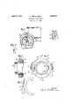
- Fig. 1 is a fragmentary side elevation of an automobile radiator and mudguard ilin lustrating the attachment of the splash-guard constructed according to my invention.
- Fig. 2 is a section on line 22 of Figure 1.
- Fig. 4 is a section through the same on line l4: of Figure 3. v
- Fig. 5 is a fragmentary detail view of a movable carrier ring for the side links.
- Fig. 6 is a fragmentary sectional rear Vele- 50 vation of wheel and upper end of splashguard securing means, the section being taken on line 66 of Figure 1.
- an automobile mud-guard on radiator ll has suspended from its lower face the upper end of a strap 12, theflower end of Whichis perforated.
- the upper ends of springs 13, 14, are secured, the low-er ends of which are attached to members or links 15, 16 having pivotally attached thereto, as at 17, a ring member 18 rotatably held in a groove ofa boss or bushing, generally designated 19 and formed by a flange 20 of the boss and a cap 21 secured upon a flange 22 of the boss.
- the rear face of the boss has attached thereto by means of inclined bars 23 a bi-partite sleeve 24 1 adapted to be clamped uponthe axle 25 of the car by means of bolts 26 passing through the pairwise arranged sockets 27, 27', of the sleeve parts.
- a bi-partite sleeve 24 1 adapted to be clamped uponthe axle 25 of the car by means of bolts 26 passing through the pairwise arranged sockets 27, 27', of the sleeve parts.
- To the lower ends of links 15, 16 is detachably secured by means of screws 28 the splash guard 29.
- a splash-guard for the wheels of motor vehicles comprising a member clamped to the wheel axle, a ring rotatably held in said member, links pivotally secured intermediate their ends to said-.ringand attached at their lower ends to -said splash-guard, springs attached at their ends to said links, a strap to which the opposite ends of said springs are attached, and means for suspending said strap from the inner face of the vehiolestmudv guard.
Description
April 12, 1932. P. OBUCHOWSKI AUTOMOBILE SPLASH GUARD Filed Dec. 31, 1929 INVENTOR. $4 (9 .4,
Patented Apr. 12, 1932 UNITED STATES PAUL OBUCHOWSKI, F srnivrronnoonnnorrou'r.
AUTOMOBILE SPLASH GUARD Application filed December 31, 1929. Serial No. 417,709.
This invention relates to a splash guard for vehicle wheels, particularly for automobiles, and it is the principal object of my invention to provide a splash guard for protecting pedestrians and other vehicles against the mud,
U etc., thrown laterally from the wheels during the rapid travel of the automobile.
Rapidly traveling automobiles in rainy weather throw the slush and watery mud laterally against pedestrians and other passing vehicles much to the inconvenience and injury of pedestrians.
My invention overcomes this disadvantage by the suspension of a yielding splash guard preventing the mud, etc., to be spread or thrown laterally to the path of the vehicle, and it is another object of my invention to suspend the splash guard in such a manner from the Vehicles axle that it will adapt itself to all oscillations of the car.
A further object of my invention is the provision of a splash-guard which is suspended from a part of the vehicle, for instance the mud-guard of an automobile to yieldingly avoid all damage to the guard by meeting obstructions in the path of the car.
A still further object of my invention is the provision of a splash-guard for automobiles of simple and inexpensive construcm tion, yet durable and efficient in operation.
These and other objects and advantages of my invention will become more fully apparent as the description thereof proceeds, and will then be specifically defined in the appended claim.
In the accompanying drawings forming a material part of this disclosure:
Fig. 1 is a fragmentary side elevation of an automobile radiator and mudguard ilin lustrating the attachment of the splash-guard constructed according to my invention.
Fig. 2 is a section on line 22 of Figure 1.
3 is an elevation of the central boss or bushing on an enlarged scale.
Fig. 4 is a section through the same on line l4: of Figure 3. v
Fig. 5 is a fragmentary detail view of a movable carrier ring for the side links.
Fig. 6 is a fragmentary sectional rear Vele- 50 vation of wheel and upper end of splashguard securing means, the section being taken on line 66 of Figure 1.
As illustrated, an automobile mud-guard on radiator llhas suspended from its lower face the upper end of a strap 12, theflower end of Whichis perforated. In the perforations the upper ends of springs 13, 14, are secured, the low-er ends of which are attached to members or links 15, 16 having pivotally attached thereto, as at 17, a ring member 18 rotatably held in a groove ofa boss or bushing, generally designated 19 and formed by a flange 20 of the boss and a cap 21 secured upon a flange 22 of the boss. The rear face of the boss has attached thereto by means of inclined bars 23 a bi-partite sleeve 24 1 adapted to be clamped uponthe axle 25 of the car by means of bolts 26 passing through the pairwise arranged sockets 27, 27', of the sleeve parts. To the lower ends of links 15, 16 is detachably secured by means of screws 28 the splash guard 29. p
The operation of my device will be entirely clear from the above description on hand of the drawings, and it will be entirely clear that the boss can be clamped by means of its bi-partite sleeve to the axle of the automobile, while the strap'12 is attached to the lower face of the mudguard and the springs hooked with their upper ends into the perforations of the strap and with their lower ends connected to the upper ends of links15, 16 carryingon the outer lower side face of the wheel 30 the splash-guard 29, so that pedestrians and other vehicles are protected from the mud laterally splashed by the quickly rotating auto wheels, while the splash guard owing to its resilient and movahle mounting and the rotation of ring 18 about the boss will readily accommodate itself to any oscillations caused by uneven roads, and swaying of the vehicle and to pass over obstacles on the road.
It will be understood that I have disclosed the preferred form of my device only and that I may make such changes in its construction as come within the scope of the appended claim without departure from my invention.
Having thus described my invention, what I claim as new and desire to secure by Letters Patent is:
A splash-guard for the wheels of motor vehicles comprising a member clamped to the wheel axle, a ring rotatably held in said member, links pivotally secured intermediate their ends to said-.ringand attached at their lower ends to -said splash-guard, springs attached at their ends to said links, a strap to which the opposite ends of said springs are attached, and means for suspending said strap from the inner face of the vehiolestmudv guard.
Signed at New York, in the county of New York and Stateof New York, this 13th day of DecemberfArD. 1929.
PAUL OBUCHOWSKI.
Priority Applications (1)
| Application Number | Priority Date | Filing Date | Title |
|---|---|---|---|
| US417709A US1853573A (en) | 1929-12-31 | 1929-12-31 | Automobile splash guard |
Applications Claiming Priority (1)
| Application Number | Priority Date | Filing Date | Title |
|---|---|---|---|
| US417709A US1853573A (en) | 1929-12-31 | 1929-12-31 | Automobile splash guard |
Publications (1)
| Publication Number | Publication Date |
|---|---|
| US1853573A true US1853573A (en) | 1932-04-12 |
Family
ID=23655095
Family Applications (1)
| Application Number | Title | Priority Date | Filing Date |
|---|---|---|---|
| US417709A Expired - Lifetime US1853573A (en) | 1929-12-31 | 1929-12-31 | Automobile splash guard |
Country Status (1)
| Country | Link |
|---|---|
| US (1) | US1853573A (en) |
-
1929
- 1929-12-31 US US417709A patent/US1853573A/en not_active Expired - Lifetime
Similar Documents
| Publication | Publication Date | Title |
|---|---|---|
| US2782053A (en) | Splash guard flap for automotive vehicles | |
| US1905674A (en) | Splash guard for motor vehicles | |
| US1853573A (en) | Automobile splash guard | |
| US1381001A (en) | Non-skid device for motor and other vehicles | |
| US1325705A (en) | William g- | |
| US1049946A (en) | Combined automobile fender and lamp-support. | |
| US1748304A (en) | Wheel guard | |
| US1867518A (en) | Mud guard for motor cars | |
| US1454738A (en) | Mud guard | |
| US1147256A (en) | Mud-guard for automobiles and the like. | |
| US1542625A (en) | Sled attachment for automobiles | |
| US2436549A (en) | Traction device | |
| US2194660A (en) | Bicycle guard | |
| US1739456A (en) | Automobile trailer-hitch attachment | |
| US1472005A (en) | Guard for motor vehicles and the like | |
| US1362841A (en) | Side-splash mud-guard | |
| US1052511A (en) | Mud-guard for automobiles. | |
| US1590375A (en) | Mud guard for motor cars | |
| US1662545A (en) | Spray screen | |
| US2252537A (en) | Splash guard for motor vehicles | |
| US1485326A (en) | Automobile bumper | |
| US857747A (en) | Mud-guard for vehicles. | |
| US1220494A (en) | Mud-deflector. | |
| US1241091A (en) | Mud-guard for bicycles and the like. | |
| US1517406A (en) | Splashguard |