US1853572A - Combination wheel - Google Patents
Combination wheel Download PDFInfo
- Publication number
- US1853572A US1853572A US541797A US54179731A US1853572A US 1853572 A US1853572 A US 1853572A US 541797 A US541797 A US 541797A US 54179731 A US54179731 A US 54179731A US 1853572 A US1853572 A US 1853572A
- Authority
- US
- United States
- Prior art keywords
- wheel
- deflated
- axle
- diameter
- periphery
- Prior art date
- Legal status (The legal status is an assumption and is not a legal conclusion. Google has not performed a legal analysis and makes no representation as to the accuracy of the status listed.)
- Expired - Lifetime
Links
Images
Classifications
-
- B—PERFORMING OPERATIONS; TRANSPORTING
- B60—VEHICLES IN GENERAL
- B60F—VEHICLES FOR USE BOTH ON RAIL AND ON ROAD; AMPHIBIOUS OR LIKE VEHICLES; CONVERTIBLE VEHICLES
- B60F1/00—Vehicles for use both on rail and on road; Conversions therefor
- B60F1/02—Vehicles for use both on rail and on road; Conversions therefor with rail and road wheels on the same axle
Definitions
- the principal object of my invention is to provide a combination wheel for vehicles having especial utility in connection with trucks or other automobiles, which may be used for riding along an ordinary highway and also along the rails of a railroad such, for example, as the railroads for steam or electric cars.
- a feature of my invention is the combination of two wheels in suitable adjacency, one of whichhas a periphery of permanent size to ride on a rail when desired and the other of which is deflatable to change the size CID of its periphery and. in the preferred form, being ada ted to become of less diameter than the first-mentioned wheel and consequently not furnishing 'an active tread surface butwhen inflated having an active tread surface and raising the first-mentioned wheel so that the latters periphery is no longer an active tread surface.
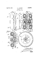
- Figure 1 is an elevation of acombination wheel embodying my invention and to be used as the rear wheel of a vehicle;
- Figure 2 is acentral longitudinal section of the combination wheel of Figure 1;
- Figure 3 is a central longitudinal section of a combination wheel embodying my invention and to be used as a front wheel;
- Figure 4 is a section on line H of F ig-" ure 2.
- Axle housing 1 is provided, as shown in Figure 2, for axle 2, which is keyed at- 3 to Y bushings 4 and 4A and 4B, the axle being held by nut- 5 against longitudinal movement with relation to the bushings.
- the bushings have annular perforated collars 6, 7' and 8. Between collars 6 and 7, and in engagement with bushing 4A, is mounted a horizontal tubular perforated portion 9 of rim 10, the latter having mounted on it a rubber shoe 11, which may be of ordinary construction and which encloses an ordinary inflatable and deflatable rubber inner tube 12 held in place as usual by walls13 of the shoe 11.
- a suitable valve may be provided for such inflation.
- tubular horizontal perforated portion 14 of wheel 15 and the tubular horizontal perforated portion 16 of rim 1? there are mounted the tubular horizontal perforated portion 14 of wheel 15 and the tubular horizontal perforated portion 16 of rim 1?, the latter having shoe 18 and inner tube 19, like shoe 11 and inner 55 tube 12.
- the horizontal perforated portions 9, 14 and. 16 are held between the collars by bolts 20 and nuts 21.
- the wheel 15 is of metal and its periphery 22 is of permanent size and is. provided with 24.
- the construction shown in Figures 1 and 2 is preferred for both of the rear wheels. although of course in the rear wheel not shown the parts 22 and 23 will be reversed.
- bushings25 and 25A are mounted on axle 26 and have collars 27 and 28 between which are mounted the horizontal tubular perforated portions 29 and 30, it being noted that the horizontal tubular portion 30 of metal wheel 31 extends to the left instead of to the right. these horizontal tubular portions being held by bolts 32 and 1 nuts 33.
- the horizontal portion 29 is integral with rim 34 which carries shoe 35 and inner tube 36.
- the wheel 15 it is desired tov use the wheel 15 to run on the rail 24 having its periphery 22 as the active tread surface.
- the tires or shoes 11 and 18, or 35. are deflated and the shoes annular lip 23 to engage the side of rail then occupy substantially the positions shown respectively in dotted lines at 37. 38 and 39 so that the shoes will not furnish an active tread surface, the lowest portions of the shoes being above the top of rail 24.
- the deflatable wheel wouldhave no active-tread action; and would be adapted to become, when necessary, of less diameter than the diameter of the solid metal wheel,
- a wheel having a periphery-of permanent size prising a wheel having a periphery-of permanent size; :and another wheel which is deflatable, the diameter of said other wheel, when the latter is inflated, being larger than the diameter of the first-mentioned wheel, and, when said other wheel isdeflated, being adapted to become of less diameter than the diameter of the first-mentioned wheel, said other wheel being so located with reference to said periphery of permanent size that it may be deflated to the normal deflated pofirst-mentioned wheel, said other wheel being deflatable to change the size of its active tread surface, said other wheel being so located with reference to said periphery of permanentv size that it may be deflated to the normal deflated position and that it will not,
- a device of the character described comprising an axle; a wheel mounted'on said axle and having a periphery 'ofpermanent size; and another wheel which is deflatable, said other wheel being mounted on said axle, the diameter of said other wheel, when the latter is inflated, being larger than the diameter of 'the first-mentioned wheel,- and,
- said other wheel when said other wheel is deflated, being adapted to become of less diameter than the diameter of the first-mentioned wheel, said other wheel being so located with reference to said peripheryof permanent size that it may be deflated to the normal deflated position and that it will not, when so deflated,
- a device of the character described comprising an axle; a wheel mounted on said axle and having a peripheryof permanent size; and two other wheels, both'of which are deflatable and when inflated being of substantially the same diameter, one of said other wheels being mounted on said axle in suitable adjacency to, andat one side of, the
- first-mentioned wheel the other of said other wheels being mounted onsaid axle in suitable adjacency to, and at the other side of, the first-mentioned wheel, the diameter of said other wheels, whenthe latter are inflated. being larger than the diameter of the first-mentioned wheel, and, when said other wheels are deflated, being adapted tobecome of less diameter than the diameter of the first-mentioned wheel, said other wheels being so located withreference tosaid periphcry of permanent size that they may be deflated to their normal deflated positions and that they will not, when so deflated, project within the path of the said periphery.
- a device of the character described comprising an axle; a wheel on said axle and having a tread surface of'permanent size;" and another wheel on said axle adjacent to the
Description
April 12,1932.
- 0. c. NUGENT CCSMBINATION WHEEL Filed June 3, 1931 fizwtenza r.
Mm C I Patented Apr. 12, 1932 UNITED I STATES v CHRISTOPHER C. NUGENT, OF WINTHBOP, MASSACHUSETTS COMBINATION WHEEL Application filed June a, 1931. Serial No. 541,797.
The principal object of my invention is to provide a combination wheel for vehicles having especial utility in connection with trucks or other automobiles, which may be used for riding along an ordinary highway and also along the rails of a railroad such, for example, as the railroads for steam or electric cars.
A feature of my invention is the combination of two wheels in suitable adjacency, one of whichhas a periphery of permanent size to ride on a rail when desired and the other of which is deflatable to change the size CID of its periphery and. in the preferred form, being ada ted to become of less diameter than the first-mentioned wheel and consequently not furnishing 'an active tread surface butwhen inflated having an active tread surface and raising the first-mentioned wheel so that the latters periphery is no longer an active tread surface.
Other features will be pointed out below.
In the drawings Figure 1 is an elevation of acombination wheel embodying my invention and to be used as the rear wheel of a vehicle;
Figure 2 is acentral longitudinal section of the combination wheel of Figure 1;
Figure 3 is a central longitudinal section of a combination wheel embodying my invention and to be used as a front wheel; and
Figure 4 is a section on line H of F ig-" ure 2.
Between collars 7 and 8, and in engagement with bushing 4B, are mounted the tubular horizontal perforated portion 14 of wheel 15 and the tubular horizontal perforated portion 16 of rim 1?, the latter having shoe 18 and inner tube 19, like shoe 11 and inner 55 tube 12.
The horizontal perforated portions 9, 14 and. 16 are held between the collars by bolts 20 and nuts 21.
The wheel 15 is of metal and its periphery 22 is of permanent size and is. provided with 24. The construction shown in Figures 1 and 2 is preferred for both of the rear wheels. although of course in the rear wheel not shown the parts 22 and 23 will be reversed.
In the form shown in Figure 3, which I prefer for front wheels, bushings25 and 25A are mounted on axle 26 and have collars 27 and 28 between which are mounted the horizontal tubular perforated portions 29 and 30, it being noted that the horizontal tubular portion 30 of metal wheel 31 extends to the left instead of to the right. these horizontal tubular portions being held by bolts 32 and 1 nuts 33. The horizontal portion 29 is integral with rim 34 which carries shoe 35 and inner tube 36.
lVhen it is desired tov use the wheel 15 to run on the rail 24 having its periphery 22 as the active tread surface. the tires or shoes 11 and 18, or 35. are deflated and the shoes annular lip 23 to engage the side of rail then occupy substantially the positions shown respectively in dotted lines at 37. 38 and 39 so that the shoes will not furnish an active tread surface, the lowest portions of the shoes being above the top of rail 24. Even if the deflation were not quite so complete as I have indicated and if the bottom of theshoe, when deflated, were slightlv below the top of rail 24, the deflatable wheel wouldhave no active-tread action; and would be adapted to become, when necessary, of less diameter than the diameter of the solid metal wheel,
an example of this being when the vehicle crosses frogs or switches or grade crossings where the top of the rail might be lower than I the surfaces adjacent to it. In such case the deflated wheel or wheels would have their tread surfaces pressed upward slightly but without said tread surfaces becoming active cry.
prising a wheel having a periphery-of permanent size; :and another wheel which is deflatable, the diameter of said other wheel, when the latter is inflated, being larger than the diameter of the first-mentioned wheel, and, when said other wheel isdeflated, being adapted to become of less diameter than the diameter of the first-mentioned wheel, said other wheel being so located with reference to said periphery of permanent size that it may be deflated to the normal deflated pofirst-mentioned wheel, said other wheel being deflatable to change the size of its active tread surface, said other wheel being so located with reference to said periphery of permanentv size that it may be deflated to the normal deflated position and that it will not,
when deflated, project within the path of said periphery. v
CHRISTOPHER 'C. NUGENT.
sition and that it will not, when so deflated, project within the path of said periph- 2. A device of the character described comprising an axle; a wheel mounted'on said axle and having a periphery 'ofpermanent size; and another wheel which is deflatable, said other wheel being mounted on said axle, the diameter of said other wheel, when the latter is inflated, being larger than the diameter of 'the first-mentioned wheel,- and,
when said other wheel is deflated, being adapted to become of less diameter than the diameter of the first-mentioned wheel, said other wheel being so located with reference to said peripheryof permanent size that it may be deflated to the normal deflated position and that it will not, when so deflated,
A project within the path of said periphery.
3. A device of the character described comprising an axle; a wheel mounted on said axle and having a peripheryof permanent size; and two other wheels, both'of which are deflatable and when inflated being of substantially the same diameter, one of said other wheels being mounted on said axle in suitable adjacency to, andat one side of, the
first-mentioned wheel, the other of said other wheels being mounted onsaid axle in suitable adjacency to, and at the other side of, the first-mentioned wheel, the diameter of said other wheels, whenthe latter are inflated. being larger than the diameter of the first-mentioned wheel, and, when said other wheels are deflated, being adapted tobecome of less diameter than the diameter of the first-mentioned wheel, said other wheels being so located withreference tosaid periphcry of permanent size that they may be deflated to their normal deflated positions and that they will not, when so deflated, project within the path of the said periphery.
4. A device of the character described comprising an axle; a wheel on said axle and having a tread surface of'permanent size;" and another wheel on said axle adjacent to the
Priority Applications (1)
| Application Number | Priority Date | Filing Date | Title |
|---|---|---|---|
| US541797A US1853572A (en) | 1931-06-03 | 1931-06-03 | Combination wheel |
Applications Claiming Priority (1)
| Application Number | Priority Date | Filing Date | Title |
|---|---|---|---|
| US541797A US1853572A (en) | 1931-06-03 | 1931-06-03 | Combination wheel |
Publications (1)
| Publication Number | Publication Date |
|---|---|
| US1853572A true US1853572A (en) | 1932-04-12 |
Family
ID=24161089
Family Applications (1)
| Application Number | Title | Priority Date | Filing Date |
|---|---|---|---|
| US541797A Expired - Lifetime US1853572A (en) | 1931-06-03 | 1931-06-03 | Combination wheel |
Country Status (1)
| Country | Link |
|---|---|
| US (1) | US1853572A (en) |
Cited By (15)
| Publication number | Priority date | Publication date | Assignee | Title |
|---|---|---|---|---|
| DE3841092A1 (en) * | 1988-12-07 | 1990-06-21 | Gegege Gmbh Grundstuecks Und B | Generalised combination vehicle (rail/road), magnetic or mechanial side rails and guide rails, magnetic drives, high-speed switches and generalised transport routes (rail/road) |
| US4943101A (en) * | 1989-02-24 | 1990-07-24 | Leonard Studio Equipment | Wheel unit |
| WO1995009738A1 (en) * | 1993-10-06 | 1995-04-13 | Harald Lehmann | Rail borne vehicle |
| WO1999041094A1 (en) * | 1998-02-17 | 1999-08-19 | Mi-Jack Products | Railwheel system for supporting loads on a road-traveling gantry crane |
| US6679535B2 (en) * | 1998-11-19 | 2004-01-20 | Alstom Holdings | Safety wheel, method of manufacturing such a wheel and bogie equipped with such a wheel |
| US20040237831A1 (en) * | 2003-05-16 | 2004-12-02 | Tremblay Richard B. | Integrated bi-modal wheel assembly |
| US20070095248A1 (en) * | 2005-11-02 | 2007-05-03 | Coots William R Jr | Method and apparatus for operating a vehicle on rails of a railroad track with an auxiliary drive assembly |
| US20100326314A1 (en) * | 2009-06-30 | 2010-12-30 | Kissel Waldemar F | Integrated Multimodal Transportation System and Associated Infrastructure |
| US8636460B1 (en) * | 2010-03-26 | 2014-01-28 | B & B Metals, Inc. | Gondola carriage assembly |
| US9096235B2 (en) | 2009-06-30 | 2015-08-04 | Wfk & Associates, Llc | Universal multimodal transportation system and associated infrastructure |
| US9096236B2 (en) | 2011-08-18 | 2015-08-04 | Wfk & Associates, Llc | Transitional mode high speed rail systems |
| US9446662B2 (en) | 2013-02-22 | 2016-09-20 | B & B Metals, Inc. | Auxiliary drive system |
| CN111497538A (en) * | 2020-04-27 | 2020-08-07 | 西华大学 | Electric road-rail dual-purpose vehicle driving device |
| WO2023156481A1 (en) | 2022-02-17 | 2023-08-24 | Nt Innovation Ohg | Rail vehicle, in particular road-rail vehicle, which is designed to change tracks, and corresponding system and method |
| DE102022110582A1 (en) | 2022-04-29 | 2023-11-02 | Nt Innovation Ohg | TWO-WAY WHEEL, TWO-WAY VEHICLE, USE OF A TWO-WAY WHEEL AS A WHEEL OF A TWO-WAY VEHICLE AND METHOD FOR OPERATING A TWO-WAY VEHICLE WITH A TWO-WAY WHEEL USING A RADIUS CHANGE OF THE HARD WHEEL |
-
1931
- 1931-06-03 US US541797A patent/US1853572A/en not_active Expired - Lifetime
Cited By (22)
| Publication number | Priority date | Publication date | Assignee | Title |
|---|---|---|---|---|
| DE3841092A1 (en) * | 1988-12-07 | 1990-06-21 | Gegege Gmbh Grundstuecks Und B | Generalised combination vehicle (rail/road), magnetic or mechanial side rails and guide rails, magnetic drives, high-speed switches and generalised transport routes (rail/road) |
| US4943101A (en) * | 1989-02-24 | 1990-07-24 | Leonard Studio Equipment | Wheel unit |
| WO1995009738A1 (en) * | 1993-10-06 | 1995-04-13 | Harald Lehmann | Rail borne vehicle |
| WO1999041094A1 (en) * | 1998-02-17 | 1999-08-19 | Mi-Jack Products | Railwheel system for supporting loads on a road-traveling gantry crane |
| US6158602A (en) * | 1998-02-17 | 2000-12-12 | Mi-Jack Products, Inc. | Railwheel system for supporting loads on a road-traveling gantry crane |
| US6230911B1 (en) * | 1998-02-17 | 2001-05-15 | Mi-Jack Products, Inc. | Rail wheel system for supporting loads on a road-traveling gantry crane |
| US6679535B2 (en) * | 1998-11-19 | 2004-01-20 | Alstom Holdings | Safety wheel, method of manufacturing such a wheel and bogie equipped with such a wheel |
| US20040108023A1 (en) * | 1998-11-19 | 2004-06-10 | Alstom Holdings And Valdunes | Safety wheel, method of manufacturing such a wheel and bogie equipped with such a wheel |
| US20040237831A1 (en) * | 2003-05-16 | 2004-12-02 | Tremblay Richard B. | Integrated bi-modal wheel assembly |
| US7077065B2 (en) | 2003-05-16 | 2006-07-18 | Richard B. Tremblay | Integrated bi-modal wheel assembly |
| US20070095248A1 (en) * | 2005-11-02 | 2007-05-03 | Coots William R Jr | Method and apparatus for operating a vehicle on rails of a railroad track with an auxiliary drive assembly |
| US7406919B2 (en) | 2005-11-02 | 2008-08-05 | Coots William R | Method and apparatus for operating a vehicle on rails of a railroad track with an auxiliary drive assembly |
| US20100326314A1 (en) * | 2009-06-30 | 2010-12-30 | Kissel Waldemar F | Integrated Multimodal Transportation System and Associated Infrastructure |
| US8342101B2 (en) * | 2009-06-30 | 2013-01-01 | Wfk & Associates, Llc | Integrated multimodal transportation system and associated infrastructure |
| US9096235B2 (en) | 2009-06-30 | 2015-08-04 | Wfk & Associates, Llc | Universal multimodal transportation system and associated infrastructure |
| US8636460B1 (en) * | 2010-03-26 | 2014-01-28 | B & B Metals, Inc. | Gondola carriage assembly |
| US9096236B2 (en) | 2011-08-18 | 2015-08-04 | Wfk & Associates, Llc | Transitional mode high speed rail systems |
| US9415783B2 (en) | 2011-08-18 | 2016-08-16 | Wfk & Associates, Llc | Transitional mode high speed rail systems |
| US9446662B2 (en) | 2013-02-22 | 2016-09-20 | B & B Metals, Inc. | Auxiliary drive system |
| CN111497538A (en) * | 2020-04-27 | 2020-08-07 | 西华大学 | Electric road-rail dual-purpose vehicle driving device |
| WO2023156481A1 (en) | 2022-02-17 | 2023-08-24 | Nt Innovation Ohg | Rail vehicle, in particular road-rail vehicle, which is designed to change tracks, and corresponding system and method |
| DE102022110582A1 (en) | 2022-04-29 | 2023-11-02 | Nt Innovation Ohg | TWO-WAY WHEEL, TWO-WAY VEHICLE, USE OF A TWO-WAY WHEEL AS A WHEEL OF A TWO-WAY VEHICLE AND METHOD FOR OPERATING A TWO-WAY VEHICLE WITH A TWO-WAY WHEEL USING A RADIUS CHANGE OF THE HARD WHEEL |
Similar Documents
| Publication | Publication Date | Title |
|---|---|---|
| US1853572A (en) | Combination wheel | |
| US3945326A (en) | Railway vehicle | |
| US2209967A (en) | Automobile wheel | |
| US1876016A (en) | Auto tire | |
| US1344238A (en) | Safety-driver for road-vehicles | |
| US1945283A (en) | Resilient tire construction for track circuit shunting | |
| US2032261A (en) | Combined felly, rim, and tire structure | |
| US1917962A (en) | Auxiliary chassis for automobiles | |
| US2075934A (en) | Emergency appliance | |
| US2044812A (en) | Antiskidding device for automobiles | |
| US917967A (en) | Wheel. | |
| US1874120A (en) | Pneumatic tire construction | |
| US2292281A (en) | Mud grip for tires | |
| US1416253A (en) | Pneumatic vehicle tire | |
| US2098859A (en) | Combined felly, rim, and dual pneumatic tire structure | |
| US1305101A (en) | Tire-protector device | |
| US1599915A (en) | Convertible hgstskxd auto sleigh | |
| GB191004972A (en) | Improvements in Means for Automatically Inflating the Tyres of Vehicle Wheels while in Motion. | |
| US2187085A (en) | Toy railway rolling stock | |
| US963304A (en) | Vehicle-wheel. | |
| US1545583A (en) | Composite pneumatic vehicle tire | |
| US1659943A (en) | Automotive vehicle | |
| US1892023A (en) | Frame support | |
| US1390024A (en) | Spring-tire | |
| US1465476A (en) | Resilient vehicle wheel |