US1853568A - Burner - Google Patents
Burner Download PDFInfo
- Publication number
- US1853568A US1853568A US46080730A US1853568A US 1853568 A US1853568 A US 1853568A US 46080730 A US46080730 A US 46080730A US 1853568 A US1853568 A US 1853568A
- Authority
- US
- United States
- Prior art keywords
- burner
- valve
- mixing chamber
- air
- casing
- Prior art date
- Legal status (The legal status is an assumption and is not a legal conclusion. Google has not performed a legal analysis and makes no representation as to the accuracy of the status listed.)
- Expired - Lifetime
Links
Images
Classifications
-
- F—MECHANICAL ENGINEERING; LIGHTING; HEATING; WEAPONS; BLASTING
- F23—COMBUSTION APPARATUS; COMBUSTION PROCESSES
- F23D—BURNERS
- F23D14/00—Burners for combustion of a gas, e.g. of a gas stored under pressure as a liquid
-
- Y—GENERAL TAGGING OF NEW TECHNOLOGICAL DEVELOPMENTS; GENERAL TAGGING OF CROSS-SECTIONAL TECHNOLOGIES SPANNING OVER SEVERAL SECTIONS OF THE IPC; TECHNICAL SUBJECTS COVERED BY FORMER USPC CROSS-REFERENCE ART COLLECTIONS [XRACs] AND DIGESTS
- Y10—TECHNICAL SUBJECTS COVERED BY FORMER USPC
- Y10T—TECHNICAL SUBJECTS COVERED BY FORMER US CLASSIFICATION
- Y10T137/00—Fluid handling
- Y10T137/8593—Systems
- Y10T137/87571—Multiple inlet with single outlet
- Y10T137/87587—Combining by aspiration
- Y10T137/87611—Flow control by varying position of a fluid inlet relative to entrainment chamber
Definitions
- This invention relates to a burner adapted for use on a work-bench and which is used from time to time in heatingV articles for treatment but which-has indeterminate periods of idleness.
- Such burners are used in such operations as heating glass tubes for use in neon lights and for other purposes and in the course of the day thewtubeis often removed for fitting or installation. Tor keep lo the burner going is wasteful and I have devised a burner which can be quickly turned off and on by one movement of one hand or foot and which has a pilot light Vwhichburns when the main burner is of and which lights the main burner at once when the main fuel inlet is again opened.
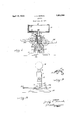
- Figure 1 is a vertical section of a burner embodying my ineo vention.
- Figure 2 is a side view of the burner shown in Figure 1 andpartly broken away at the bottom.
- Figure 3 is a detail section of a burner of preferred construction.
- the burner can be fixed in place but is preferably and usually made portable having a base 10 on which the tube casing 11 is mounted.
- the casing is supported on spaced legs 12 and is supplied at the top with a main. burner 13.
- This burner is of any desired form but is preferably of the long cylindrical type.
- ,'Iheplate 14 is perforated at the top to provide flame along the top of the burner.
- a desirable form of burner is such as described in Patent No. 1,704,359, dated March 5, 1929.
- the nipple 16 acts as a sup- A port for the burner and also supplies fuel from the mixing chamber 17.
- the mixing chamber is movable to close the air inlet 18 and gas inlet 19 at the same time.
- this ksimultaneous opening and closing of the air and gas inlets is done by Ysliding the mixing chamber up and, down.
- the chamber is in the form of a sleeve which slides in the bore 20 of the casing 11.
- a nozzle 21 which has a 1930.
- the mixing chamber 17 and the nozzle 21 therefore form a valve which opens and closes the air and gas linlets simultaneously.
- a valvedl pipe 24 supplies the gas inlet 19 and a valved pipe 25 supplies the air inlet 18 with air under pressure, in the accepted practice.
- the valve is moved up and down by a lever 26 which is pivoted at one end, at 27, to theY base and is Vconnected by the link 28 to the* when turned on.
- This ignition is due to a pilot light in the form of a by-pass 32 which extends from the gas inlet, in front of the valve 17 and to the burner where its outlet 33 is restricted to the desired extent.
- by-pass is usually in the form of a small pipe passed up inside the main burner casing and having at its lower part a connecting passage 34 and lis supplied with a needle valve 35.y
- the burner shown in Figure 3 has a burner plate 14 with its side extensions 36 with the small holes 37 slightly under the overhanging edges of the outer shell 13 to prevent the complete extinguishing of the flame under a strong draft.
- Vhile the word handle has been used in this specification for the lever for operating the valve to supply or cut ofi" fuel toand from the main. burner, this termis designed to includeanyother form of operatingmech- Vhen the valve is to be lowered
- the l anism such as might be connected to a foot treadle on the machine.
- a burner comprising a casing having burner element at the top, air and gas inlets at the sides, a Valve slidable in the casing and having a port connecting with the air inlet when the valve is up, the valve being below the gas inlet When the valve is down, the Valve acting to close bothvinlets When in lowered position, a handle for the Valve, a stop to hold the handle in raised position, and a by-pa'ss from the gas inlet to the burner and in front of the Valve to serve as a pilot light.
Description
April l2, 1932. 1. ALMomcK l 1,853,568-
BURNER Filed June 13, 1930 v lNvENToR W ATTO EY Patented pr. 172, 1932 UNIT-ED STATES JOSEPH A.. MORICK, OF KENILWORTH, NEW JERSEY, ASSIGNOR TO EISLER IE}I.1LG'1RIC'V vi'mrtzla'r oFF-ier:
CORPORATION, OF NEWARK, NEW JERSEY BURNER Application filed June 13,
This invention relates to a burner adapted for use on a work-bench and which is used from time to time in heatingV articles for treatment but which-has indeterminate periods of idleness. Such burners are used in such operations as heating glass tubes for use in neon lights and for other purposes and in the course of the day thewtubeis often removed for fitting or installation. Tor keep lo the burner going is wasteful and I have devised a burner which can be quickly turned off and on by one movement of one hand or foot and which has a pilot light Vwhichburns when the main burner is of and which lights the main burner at once when the main fuel inlet is again opened. l
The invention is illustrated in the accompanying drawings, in which Figure 1 is a vertical section of a burner embodying my ineo vention. Figure 2 is a side view of the burner shown in Figure 1 andpartly broken away at the bottom. Figure 3 is a detail section of a burner of preferred construction.
The burner can be fixed in place but is preferably and usually made portable having a base 10 on which the tube casing 11 is mounted. The casing is supported on spaced legs 12 and is supplied at the top with a main. burner 13. This burner is of any desired form but is preferably of the long cylindrical type. ,'Iheplate 14 is perforated at the top to provide flame along the top of the burner. A desirable form of burner is such as described in Patent No. 1,704,359, dated March 5, 1929. The nipple 16 acts as a sup- A port for the burner and also supplies fuel from the mixing chamber 17. The mixing chamber is movable to close the air inlet 18 and gas inlet 19 at the same time. In the form shown this ksimultaneous opening and closing of the air and gas inlets is done by Ysliding the mixing chamber up and, down. The chamber is in the form of a sleeve which slides in the bore 20 of the casing 11. In the 5 mixing chamber is a nozzle 21 which has a 1930. Serial No. 460,807.
right-angled channel 22 which conducts air from the yair inlet 18 to the mixing chamber whenk the mixing chamber is raised. The mixing chamber has an opening 23 which is in line with the gas inlet 19 when the mixing chamber is raised. The mixing chamber 17 and the nozzle 21 therefore form a valve which opens and closes the air and gas linlets simultaneously. A valvedl pipe 24 supplies the gas inlet 19 and a valved pipe 25 supplies the air inlet 18 with air under pressure, in the accepted practice.
The valve is moved up and down by a lever 26 which is pivoted at one end, at 27, to theY base and is Vconnected by the link 28 to the* when turned on. This ignition is due to a pilot light in the form of a by-pass 32 which extends from the gas inlet, in front of the valve 17 and to the burner where its outlet 33 is restricted to the desired extent. by-pass is usually in the form of a small pipe passed up inside the main burner casing and having at its lower part a connecting passage 34 and lis supplied with a needle valve 35.y
The burner shown in Figure 3 has a burner plate 14 with its side extensions 36 with the small holes 37 slightly under the overhanging edges of the outer shell 13 to prevent the complete extinguishing of the flame under a strong draft.
Vhile the word handle has been used in this specification for the lever for operating the valve to supply or cut ofi" fuel toand from the main. burner, this termis designed to includeanyother form of operatingmech- Vhen the valve is to be lowered The l anism such as might be connected to a foot treadle on the machine.
I claim Y A burner comprising a casing having burner element at the top, air and gas inlets at the sides, a Valve slidable in the casing and having a port connecting with the air inlet when the valve is up, the valve being below the gas inlet When the valve is down, the Valve acting to close bothvinlets When in lowered position, a handle for the Valve, a stop to hold the handle in raised position, and a by-pa'ss from the gas inlet to the burner and in front of the Valve to serve as a pilot light.
In testimony whereof he aHiXeshis signature.
JOSEPH A. MORICK. Y
Priority Applications (1)
| Application Number | Priority Date | Filing Date | Title |
|---|---|---|---|
| US46080730 US1853568A (en) | 1930-06-13 | 1930-06-13 | Burner |
Applications Claiming Priority (1)
| Application Number | Priority Date | Filing Date | Title |
|---|---|---|---|
| US46080730 US1853568A (en) | 1930-06-13 | 1930-06-13 | Burner |
Publications (1)
| Publication Number | Publication Date |
|---|---|
| US1853568A true US1853568A (en) | 1932-04-12 |
Family
ID=23830155
Family Applications (1)
| Application Number | Title | Priority Date | Filing Date |
|---|---|---|---|
| US46080730 Expired - Lifetime US1853568A (en) | 1930-06-13 | 1930-06-13 | Burner |
Country Status (1)
| Country | Link |
|---|---|
| US (1) | US1853568A (en) |
Cited By (1)
| Publication number | Priority date | Publication date | Assignee | Title |
|---|---|---|---|---|
| US3159203A (en) * | 1961-08-11 | 1964-12-01 | Robertshaw Controls Co | Pilot burner |
-
1930
- 1930-06-13 US US46080730 patent/US1853568A/en not_active Expired - Lifetime
Cited By (1)
| Publication number | Priority date | Publication date | Assignee | Title |
|---|---|---|---|---|
| US3159203A (en) * | 1961-08-11 | 1964-12-01 | Robertshaw Controls Co | Pilot burner |
Similar Documents
| Publication | Publication Date | Title |
|---|---|---|
| BRPI1016196B1 (en) | GAS BURNER AND HOUSEHOLD KITCHEN | |
| US1791565A (en) | Gas burner | |
| US1853568A (en) | Burner | |
| US1394721A (en) | Gas-burner | |
| US2183273A (en) | Gas lighter for wick oil burners | |
| US1617399A (en) | Oil-burning pressure torch | |
| US2153497A (en) | Blast burner | |
| US1987386A (en) | Gas burner | |
| US1378675A (en) | Automatic asphalt-smoothing iron | |
| US1991609A (en) | Heating system | |
| US2008882A (en) | Lamp | |
| US1827951A (en) | Stove | |
| US1828779A (en) | Burner | |
| US1024320A (en) | Soldering-iron heater. | |
| US2081507A (en) | Gas stove | |
| US1057814A (en) | Gas-burner. | |
| US1484805A (en) | Automatic-lighting gas-stove burner | |
| US2281563A (en) | Pilot for gas ranges | |
| US989766A (en) | Lamp. | |
| US1297374A (en) | Gas-burning appliance. | |
| US1222084A (en) | Burner. | |
| US1920933A (en) | Liquid fuel vapor burner | |
| US1132722A (en) | Gas burner and mixer. | |
| USRE18339E (en) | Automatic gas igniter | |
| US1629909A (en) | Blowtorch |