US1853567A - Toy aeroplane - Google Patents
Toy aeroplane Download PDFInfo
- Publication number
- US1853567A US1853567A US156554A US15655426A US1853567A US 1853567 A US1853567 A US 1853567A US 156554 A US156554 A US 156554A US 15655426 A US15655426 A US 15655426A US 1853567 A US1853567 A US 1853567A
- Authority
- US
- United States
- Prior art keywords
- aircraft
- toy
- aeroplane
- flight
- gear
- Prior art date
- Legal status (The legal status is an assumption and is not a legal conclusion. Google has not performed a legal analysis and makes no representation as to the accuracy of the status listed.)
- Expired - Lifetime
Links
Images

Classifications
-
- A—HUMAN NECESSITIES
- A63—SPORTS; GAMES; AMUSEMENTS
- A63H—TOYS, e.g. TOPS, DOLLS, HOOPS OR BUILDING BLOCKS
- A63H27/00—Toy aircraft; Other flying toys
- A63H27/04—Captive toy aircraft
Definitions
- This invention relates to toy vehicles generally, and more particularly to toy aircraft. It is the object of the present invention to provide a toy vehicle which will perform 5 various stunts in the course of its travel.”
- the present invention relates to the type of toy aircraft in which a toy in the form. of an aeroplane is made to rise from the ground by the aid of a motor and air propeller means 10 and then to swing in a circular path, thus simulating the flight of aircraft, and then to descend to the ground.
- Toys of this general type known hitherto were attached to an arm which was provided witha counterbalance at,
- toy aeroplane points downward, and flies downward for a short while, but before it reaches the ground it straightens out into a horizontal position and reascends to its normal height and con tinues its flight.
- Another stunt which the toy aeroplane is made to perform by the-pres ent device is to loop the loop in which case it is rotated through 360 on its transverse axis while in flight, and then resumes its normal course.
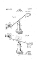
- Figure 1 shows one embodiment of the invention illustrating the devices in the starting position.
- Figure 2 shows the same devices illustrated in Figure 1 in flight, and shows the stunt performing aircraft in a vertical position.
- Figure 3 is a detail showing on the line 5 33 of Figure 1.
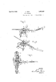
- FIG. 5 shows another form of the invention, the toy aircraft beingillustrated in the starting position
- Figure 6 shows the same form as that il-, lustrated in Figure 5, in operation, and illustrates in dotted linesthe performing toy aircraft in its inverted position.
- Figure 7 is a detail showingdevices for rotating the performing toy aircraft in inoperative position.
- Figure 8 shows the same devices in their operative position.
- Figure 9 is a sectional View of Figure taken on the line 9.9.
- 10 illustrates a base,-preferably in the formof a tower, which is so con v structed that the beam 11 maybe pivotally and .removably mounted thereon.
- the base 10 is provided with a cup-shaped gear device 12 having an aperture'l3 in its base .and mounted on the tower by means of the support 14.
- the beamll consists of two arms 15 and 16 which arepivotally attached to each other by means of the horizontal pin 17, the pin 17 also serving to pivotally attach to the arms the vertical pin 18 which carries a collar 19 serving as a stop and limiting the downward movement of the pin 18 and the beam. It willibe .se'en,.
- the beam 11 which comprises the arms 15 and 16 may be readily removed. from the tower and may .be replaced thereon by positioning the pin 18 in the aperture 13, the'collar 19 serving asa bearingsurface and cooperating with the base of thecup l2 to permit the rotationof the beam.
- Each'ofthe arms 15 and 16 are troughshaped in cross section with the open face of the trough pointed downward.
- the oivoted end of the arm 16 is bent slightly upward as will be seen at 20, the sides of the trough'of the bent portion 20 being provided with notches 21 which permit the arm 16 to move from the position shown in Figures 1 and 3 to that shown in Figures 2 and 4, without touching the gear, 12.
- the pivoted end of the arm 16 beyond the bent portion 20, comprises the forked elements 21 and 22 which I carry the pivot pin 17, and straddles the correspondingly forked end of the arm 15 and the pin 18.
- the free end of the arm 16 is provided with a hook 23 which is adapted to cooperate with an eye 24011 the toy aircraft 25 in order to suspend the same. 7
- the pivoted end of thearm 15 is also forked to straddle the pin 18, and is provided with lugs 26 which overlie the upper edges of the forked portions 21 and 22 of the arm 16.
- the trough-shaped arm 15 serves to support therod 28 in the bearing plate 27 as well as to attach the arm 15 to the pivot pin 18 and to the arm 16 in such a manner as to permit of the planetary movement of the toy aircraft 29 around the tower 10 and also to permit of the rotational move- .ment of the rod 28 on its own longitudinal axis and with it the rotation of the toy aircraft 29 on its transverse axis.
- the troughshaped arm 15 also is extendedto the proximity of the toy aircraft 29 so as to cover the rod 29 and give the entire device a better appearance.
- the rod 28 is provided with a gear 30 cooperating withthe gear 12 for rotating the rod 28 on its longitudinal axis and the toy aircraft 29 on its transverse axis.
- thetoy aeroplane 25 is sl ghtly heavier than the toy aeroplane 29, with the result that in the starting position the aeroplane 25 will rest on the ground whereas the aeroplane 29wi1l behiorh over the ground in the position shown in Figures 1 and 3, with the result that the gears 12 and 30 are out of engagement with each other. It is obvious, however. that if desired. the two aeroplanes 25 and 29 may be substantially the same in weight and the desired effect may be obtained by lengthening. the arm 16 as compared with the arm 15.
- the toy aeroplane 25 is provided with a spring-motorwhich may be wound by the aid of the key 31 so as to rotate the propeller 32 whereas-the aeroplane 29 is not provided with a spring motor although it is provided with an air propeller in order to simulate the appearance of an aeroplane.
- the two aeroplanes may be identicalin construction, the difference in weight being obtained by the weight ofthe spring motor on the aeroplane 25.
- aeroplane is caused to perform various stunts 33 is provided with a spring motor 34 which 1' may be wound by the aid of a key 35 and is provided with devices which cause the rotation of the aeroplane 330111115 transverse axis in a manner similar to that in the first embodiment; in the present case, however, the engagement is caused when the aeroplane 33 is raised and disengagement is caused by the lowering of said aeroplane.
- the arms 15 and 16 of the beam are mounted upon the tower 10 by the aid of the pin 18 in substan tially the same manner as that shown in the previous embodiment.
- the arm 16' is provided with a hook 23 to cooperate with an eye 24 to sustain a cooperating counter-balw ance which in the present case is illustrated in the form of an airship.
- the aeroplane 33 is made slightly heavier thanv the counter-balance 25' with the result that in the ner of attaching the aeroplane 33 to the arm 15' is varied from that shown in the first embodiment of the invention.
- the aeroplane 33 is provided with a bracket 39 which is attached to the aeroplane at its foot 40 and is provided with an apertured extension 41 and is also provided with an apertured stop plate 42 at an intermediate point thereof.
- the bent rod 43 passes through the apertures in the plates 41 and 42 and carries at its forward end the gear 38.
- the rod 43 also carries a transverse stop 44 and a spring 45 which is disposed between the plate 41 and the plate 46 which is fixedly mounted on the rod 43.
- the bent portion of the rod 43 is frictionally held in the arm 15 of the beam.
- the aeroplane 33 is transversely slidable from the position shown in Figures 5, 7 and 9 in which it will be seen the plate 42 abuts against the rear face of the gear 38 with the result that the gears 37 and 38 are out of engagement, to the position shown in Figures 6 and 8 in which the spring 45 has been somewhat compressed, the plate 42 abuts the stop pin 44 and the gears 38 and 37 are in engagement torotate the aeroplane 33 on its transverse axis.
- I provide a longitudinally slidable strip 47 which is mounted on the side of the aeroplane body by the aid of a longitudinal slot in the strip 47 and by a rivet 48.
- Thestrip 47 is provided with a projection 49 which is designed to cooperate with a projection 50 on the propeller shaft 51. In the position shown in Figure 9, the projections 49 and 50 are out of engagement with each other.
- the strip 47 is moved downward by the aid of the manual lug 55 to a position where 49 and 50 will be superimposed, with the result that any rotation of the spring motor shaft will not cause any rotation of the propeller shaft, thereby permitting the storage of energy in the spring motor.
- the strip 47 is provided with the forked ends 53 which, in the position shown in Figure 9, permit the free relative movement of the aeroplane and the rod 43 and'also permit thergear 38 to pass without engaging the. fork 53.
- the fork 52, 53 also straddles the rod 43.
- the aeroplane is moved to the position shown in.
- the strip 47 is moved downward to the position where 49 and 50 cooperate to prevent the rotation of the aeroplane shaft 51 and in this position the fork 52, 53 will. straddle .the rod 43 on'the free end thereof, namely at the point 54, and thereby prevent the accidental displacement of the aeroplane with relation to.
- the aeroplane 33 is normally in its resting position.
- the strip 47 is moved to its stop position and the motor is wound, thereby storing energy in the spring 34.
- the strip 47 is then moved back to the position shown in Figure 9 and the motor will be'r leased and the air propeller will rotate-
- the rotation of the propeller will cause the aeroplane 33 to ascend and to revolve about a base or tower 10.
- the aeroplane 33 is in a position approximately as shown in Figure 6, the weight of the aeroplane 33 operating against the spring 45, will cause the aeroplane to slide to the position shown in Figure 8 and thereby'cause the engagement of the gear 38 with the gear 37 which in turn will cause the rotation of the aeroplane 33 on its transverse axis.
- a toy aircraft comprising a support, a beam rotatable on said support, a toy aircraft rotatably mounted on said beam by means of a transverse spindle, motor means for rotating said beam and aircraft to simulate aircraft flight, and means comprising gear connections between the support and aircraft for rotating said aircraft on said transverse spindle in the course of its flight.
- a self-propelled toy aircraft comprising a support, a beam rotatable on said support, a toy aircraft rotatably mounted on one end of said beam by ineans of a transvere spindle, motor and air propeller means on said aircraft for rotating said beam and aircraft to simulate aircraft flight, and means comprising disengageable gear connections between the support and'aircraft for rotating said aircraft on said transverse spindle in the course of its flight whenever said gear connections are engaged.
- a toy aircraft comprising a support, a beam rotatable on said support, a toy aircraft rotatably mounted on said beam by means of a transverse spindle, -motor means for rotating said beam and aircraft to simulate aircraft flight, and means comprising a gear on said aircraft and another gear meshing therewith and co operatively related to said support for rotating said aircraft on said transverse spindle in the courseof its flight.
- a self-propelled toy aircraft comprising a support, a toy aircraft rotatable about a transverse axis and revolvable about said support, motor means for revolving said aircraft about said support in order to simulate aircraft flight, and means'comprising a gear on said aircraft and another gear meshing therewith and cooperatively related to said support for rotating said aircraft on to said transverse axis in'the course of its flight.
- a toy aircraft comprising a support, a beam rotatable on said support, a toy aircraft tiltably mounted onone end of said beam, motor means for rotating said beam and aircraft to simulate aircraft flight, means to tilt said aircraft, and means responsive to the vertical movements of the aircraft 'for making the tiltin means operative in order to tilt said aircraft about a transverse axis.
- 8..A self-propelled toy aircraft comprising a support, a beam rotatable on said support, a toy aircraft mounted on a transverse spindle at one end of said beam, motor.
- air propeller means on said aircraft for rotating said beam and aircraft to simulate aircraft flight, means to rotate saidaircraft about the transverse spindle, and means responsive to the vertical movements of the aircraft for making the rotating means operative in order to rotate said aircraft on its transverse spindle.
- a toy aircraft comprising a support, a beam rotatable on said support, a toy aircraft mounted on a transverse spindle at one end of said beam, motor means for rotating said beam and aircraft to simulate aircraft flight, and means operable by a drop of the aircraft relative to a prior altitude to rotate same on its tranverse spindle.
- a self-propelled toy aircraft comprising a support, a beam rotatable on said support, a toy aircraft mounted on a transverse spindle at one end of said beam, motor and air propeller means on said aircraft for rotating saidbeam and aircraft to simulate aircraft flight, means to rotate the aircraft about the spindle, and me'ans operableby a drop of the aircraft relative to a prior'altitppile for making said rotating means opera e.
- a toy aircraft comprising a support, a beam'rotatable on said support, a toy aircraft mounted on a transverse spindle at one end of said beam, motor and air propeller means for rotating said beam and aircraft to simulate aircraft flight, and means operable'by a rise of the aircraft to rotate the same on its transverse spindle.
- a self-propelled toy aircraft comprising a support, a beam rotatable on said support, a toy aircraft mounted on a transverse spindle at one end of-said beam, a counterbalance on the other end, motor and air propeller means on said aircraft for rotating said beam and aircraft to simulate aircraft flight, means to rotate the aircraft about the spindle, and means operable by a rise of the aircraft for making said rotating means operative in order to rotate the aircraft on its transverse axis.
- a toy aircraft comprising a base, a beam having two pivoted arms rotatably mounted on said base, a toy aircraft on each free end of said beam, one of said aircraft being mounted for rotation about a transverse axis, motor and air propeller means mounted on one of said aircraft to revolve said beam and aircraft to simulate flight, and means operable by a change in the level of flight of said aircraft torotate the rotatably mounted one of said aircraft on its transverse axis.
- beam having two pivoted arms rotatably mounted on said base, a toy aircraft on each free end of said beam, one of said aircraft being mounted for rotation about a transverse axis, motor and air propeller means mounted on one of said aircraft to revolve said beam and aircraft to simulate flight, means to rotate the rotatable aircraft about its transverse axis, and means operable by a rise of one of the aircraft for making the ro-' tating means operative in order to rotate the rotatable aircraft on .its transverse axis.
- a toy aircraft comprising a base, a beam having two pivoted arms rotatably mounted on said base, a toy aircraft on each free end of said beam, one of said aircraft being mounted for rotation about a transverse axis, motor and air propeller means mounted on one of said aircraft to revolve said beam and aircraft to simulate flight, means to rotate the rotatable aircraft about its transverse axis, and means operable by a drop of one of said aircraft relative to a prior altitude for making the rotating means operative in order to rotate the rotatable aircraft on its transverse axis.
- a toy aircraft comprising a base, a beam having two pivoted arms rotatably mounted on said base, a toy aircraft on each free end of said beam, motor and air propeller means mounted on one of said aircraft to revolve said beam and aircraft to simulate flight, a gear associated with said base, a second gear engageable with said first mentioned gear on a drop in the level flight of one of said aircraft, and means connecting said second gear with said last mentioned aircraft whereby said last mentioned aircraft is rotated on a transverse axis when said gears are in engagement.
- a toy aircraft comprising a base, a beam rotatably mounted on said base, a counterbalance on one end of said beam and a toy aircraft on the other, motor and air propeller means for revolving said beam and aircraft to simulate aircraft flight, and gears on said aircraft and beam engageable with each other on a change in the level of flight to rotate said aircraft in the course of'its flight.
- a toy aircraft comprising a base, a beam rotatably mounted on said base, a toy aircraft on said beam, motor means for revolving said beam and aircraft to simulate aircraft flight, and gears on said aircraft and beam engageable with each other on a change in the level of flight to rotate said aircraft on one of its axes in the course of its flight.
- a toy aircraft comprising a base, a beam rotatably mounted on said; base, and a toy aircraft on said beam, motor and air propeller means for revolving said beam and aircraft to simulate aircraft flight, and gears on' said aircraft and beam engageable with each other on a change in the level of flight to rotate said aircraft on its transverse axis in the course of its flight.
- a toy aircraft comprising a base, a base, a base, a base, a base, a
- a toy aircraft comprising a base, a beam rotatably mounted on said base, a toy aircraft on said beam slidably mounted thereon, spring motor and air propeller means for revolving the beam and aircraft and means for rotating the aircraft on one of its axes, said means being normally inoperative and adapted to be made operative by the sliding movement of the aircraft.
- a toy aircraft comprising a base, a beam rotatably mounted on said base, a counterbalan'ce' on one end of said beam, a toy aircraft on the other end slidably mounted thereon, a gear on said aircraft, another gear on said beam normally out of engagementwith said first gear, and manually operable means for holding said propeller against rotation and said gears out of engagement when said 7 motor is being wound.
- a self-propelled miniature or toy aircraft comprising an upright support, abeam rotatably supported on said support, a spindle projecting from one end of the beam, a toy aircraft mounted on said spindle with the pintle extending transversely thereof, a motor and propeller on said aircraft whereby said aircraft is caused to revolve about the support in simulation of the flight of an'aircraft, and means causing said aircraft to repeatedly tilt or/ and completely rotate on said transverse spindle so as to continuously perform aerial stunts in the course of its flight.
Description
A ril 12, 1932. L, M RX 1,853,567
TOY AEROPLANE Filed Dec. 25; 1926 3 Sheets-Sheet l IN\ IENOR T Lo u I 5 Ma r1 ATTORNEYS April 12, 1932. MARX 1,853,567
TOY AEROPLANE Filed Dec. 23, 1926 s ShGGtS' 2 INVENTOR Lou i 5 M a rx BY ATTORNEYS April 12, 1932.
TOY AEROPLANE L. MARX Fit. 7.
Filed Dec. 23 1926 3 Sheets-Sheet 3 INVENTOR Louls Marx ATTORNEYS Patented Apr. 12, 1932 UNITED STATES LOUIS MARX, OF BROOKLYN, NEW YOIRK TOY AEROPLANE .Application filed December 23, 1926. Serial No. 156,554.
This invention relates to toy vehicles generally, and more particularly to toy aircraft. It is the object of the present invention to provide a toy vehicle which will perform 5 various stunts in the course of its travel."
The present invention relates to the type of toy aircraft in which a toy in the form. of an aeroplane is made to rise from the ground by the aid of a motor and air propeller means 10 and then to swing in a circular path, thus simulating the flight of aircraft, and then to descend to the ground. Toys of this general type known hitherto were attached to an arm which was provided witha counterbalance at,
points downward, and flies downward for a short while, but before it reaches the ground it straightens out into a horizontal position and reascends to its normal height and con tinues its flight. Another stunt which the toy aeroplane is made to perform by the-pres ent device is to loop the loop in which case it is rotated through 360 on its transverse axis while in flight, and then resumes its normal course. a
The invention will be more clearly understood from the following specification and the drawings which constitute a part of this application.
In the drawings:
Figure 1 shows one embodiment of the invention illustrating the devices in the starting position.
Figure 2 shows the same devices illustrated in Figure 1 in flight, and shows the stunt performing aircraft in a vertical position.
Figure 3 is a detail showing on the line 5 33 of Figure 1.
plane is caused to be rotated through an ail-,1 gle perhaps approximating 90, so that it Figure 4 shows the same detail in operative position.
Figure 5 shows another form of the invention, the toy aircraft beingillustrated in the starting position,
Figure 6showsthe same form as that il-, lustrated in Figure 5, in operation, and illustrates in dotted linesthe performing toy aircraft in its inverted position. I
Figure 7 is a detail showingdevices for rotating the performing toy aircraft in inoperative position. i
Figure 8 shows the same devices in their operative position.
Figure 9 is a sectional View of Figure taken on the line 9.9. Q
In the embodiment of theinvention shown in Figures 1 to 4, 10 illustrates a base,-preferably in the formof a tower, which is so con v structed that the beam 11 maybe pivotally and .removably mounted thereon. The base 10 is provided with a cup-shaped gear device 12 having an aperture'l3 in its base .and mounted on the tower by means of the suport 14. The beamll consists of two arms 15 and 16 which arepivotally attached to each other by means of the horizontal pin 17, the pin 17 also serving to pivotally attach to the arms the vertical pin 18 which carries a collar 19 serving as a stop and limiting the downward movement of the pin 18 and the beam. It willibe .se'en,. therefore, that the beam 11 which comprises the arms 15 and 16, may be readily removed. from the tower and may .be replaced thereon by positioning the pin 18 in the aperture 13, the'collar 19 serving asa bearingsurface and cooperating with the base of thecup l2 to permit the rotationof the beam.
The pivoted end of thearm 15 is also forked to straddle the pin 18, and is provided with lugs 26 which overlie the upper edges of the forked portions 21 and 22 of the arm 16. The portion of the trough of the arm 15 that lies between the forked portions of the pivoted end of the arm, .is bent clownwardly to form an apertured bearing plate 27 which rotatably supports the rod 28, the other end of the rod being attached to the .toy aircraft 29. The trough-shaped arm 15 serves to support therod 28 in the bearing plate 27 as well as to attach the arm 15 to the pivot pin 18 and to the arm 16 in such a manner as to permit of the planetary movement of the toy aircraft 29 around the tower 10 and also to permit of the rotational move- .ment of the rod 28 on its own longitudinal axis and with it the rotation of the toy aircraft 29 on its transverse axis. The troughshaped arm 15 also is extendedto the proximity of the toy aircraft 29 so as to cover the rod 29 and give the entire device a better appearance. V
The rod 28 is provided with a gear 30 cooperating withthe gear 12 for rotating the rod 28 on its longitudinal axis and the toy aircraft 29 on its transverse axis.
In the embodiment of the invention shown in Figures 1 to 4, thetoy aeroplane 25 is sl ghtly heavier than the toy aeroplane 29, with the result that in the starting position the aeroplane 25 will rest on the ground whereas the aeroplane 29wi1l behiorh over the ground in the position shown in Figures 1 and 3, with the result that the gears 12 and 30 are out of engagement with each other. It is obvious, however. that if desired. the two aeroplanes 25 and 29 may be substantially the same in weight and the desired effect may be obtained by lengthening. the arm 16 as compared with the arm 15.
In the embodiment'of the invention shown in Figures'l to 4, the toy aeroplane 25 is provided with a spring-motorwhich may be wound by the aid of the key 31 so as to rotate the propeller 32 whereas-the aeroplane 29 is not provided with a spring motor although it is provided with an air propeller in order to simulate the appearance of an aeroplane. In this embodiment, therefore,the two aeroplanes may be identicalin construction, the difference in weight being obtained by the weight ofthe spring motor on the aeroplane 25. I do not, however, wish to be limited to this manner of construction but it is obvious As'the aeroplane 29 is lowered to the positionshown in Figures 2 and 4c, the gear 30 will engage with the gear 12 and cause the rotation of the aeroplane 29 on its transverse axis, and thereby cause the same to perform stunts such as a nose dive or the loop the loop,
as defined hereinabove. In the course of the operation of the device, therefore, it frequently happens that after the gears 30 and 12 have come into engagement and the toyaeroplane 29 has started its rotation on its transverse axis, that as a result thereof the movement of the aeroplanes are slowed down slightly which inturn causes the aeroplane 25 to be lowered appreciably and'the aeroplane 29 to be raised sufficiently so that the gear 30 gets into a position out of engagement with the gear 12 and the rotation of the aeroplane 29is therefore stopped prematurely. This manner of operation of the 4 device causes an erratic variation in the stunts performed by the aeroplane 29 with the result that at times the aeroplane 29 will perform a loop the loop which is caused by a complete rotation of the aeroplane 29 on its transverse axis as illustrated in dotted lines in Figure 2, Whereas at other times it will perform a nose ,dive which is caused by an incomplete rotation of the aeroplane 29, which is illustrated by the dotted line position 29 of the aeroplane 29, and at still other times it will merely appear to descend and reascend in the course of its flight. It will be seen, therefore, thatby the above described construction, an
aeroplane is caused to perform various stunts 33 is provided with a spring motor 34 which 1' may be wound by the aid of a key 35 and is provided with devices which cause the rotation of the aeroplane 330111115 transverse axis in a manner similar to that in the first embodiment; in the present case, however, the engagement is caused when the aeroplane 33 is raised and disengagement is caused by the lowering of said aeroplane.
In this form of the invention the arms 15 and 16 of the beam, are mounted upon the tower 10 by the aid of the pin 18 in substan tially the same manner as that shown in the previous embodiment. The arm 16' is provided with a hook 23 to cooperate with an eye 24 to sustain a cooperating counter-balw ance which in the present case is illustrated in the form of an airship. Y The aeroplane 33 is made slightly heavier thanv the counter-balance 25' with the result that in the ner of attaching the aeroplane 33 to the arm 15' is varied from that shown in the first embodiment of the invention. The aeroplane 33 is provided with a bracket 39 which is attached to the aeroplane at its foot 40 and is provided with an apertured extension 41 and is also provided with an apertured stop plate 42 at an intermediate point thereof. The bent rod 43 passes through the apertures in the plates 41 and 42 and carries at its forward end the gear 38. The rod 43also carries a transverse stop 44 and a spring 45 which is disposed between the plate 41 and the plate 46 which is fixedly mounted on the rod 43. The bent portion of the rod 43 is frictionally held in the arm 15 of the beam. With this construction the aeroplane 33 is transversely slidable from the position shown in Figures 5, 7 and 9 in which it will be seen the plate 42 abuts against the rear face of the gear 38 with the result that the gears 37 and 38 are out of engagement, to the position shown in Figures 6 and 8 in which the spring 45 has been somewhat compressed, the plate 42 abuts the stop pin 44 and the gears 38 and 37 are in engagement torotate the aeroplane 33 on its transverse axis.
In order to facilitate the winding of the spring motor and to hold the propeller against rotation during such winding, and also to hold the gears 37 and 38 out of engagement during such rotation, I provide a longitudinally slidable strip 47 which is mounted on the side of the aeroplane body by the aid of a longitudinal slot in the strip 47 and by a rivet 48. Thestrip 47 is provided with a projection 49 which is designed to cooperate with a projection 50 on the propeller shaft 51. In the position shown in Figure 9, the projections 49 and 50 are out of engagement with each other. When desired, the strip 47 is moved downward by the aid of the manual lug 55 to a position where 49 and 50 will be superimposed, with the result that any rotation of the spring motor shaft will not cause any rotation of the propeller shaft, thereby permitting the storage of energy in the spring motor. The strip 47 is provided with the forked ends 53 which, in the position shown in Figure 9, permit the free relative movement of the aeroplane and the rod 43 and'also permit thergear 38 to pass without engaging the. fork 53. When, however,.the strip 47 is moved downward into the position'where 49 and 50 are superimposed, the fork 52, 53 also straddles the rod 43. When, therefore, it is desired to wind the spring motor 34, the aeroplane is moved to the position shown in. Figure 9, the strip 47 is moved downward to the position where 49 and 50 cooperate to prevent the rotation of the aeroplane shaft 51 and in this position the fork 52, 53 will. straddle .the rod 43 on'the free end thereof, namely at the point 54, and thereby prevent the accidental displacement of the aeroplane with relation to.
the rod 43, and thereby prevent any accidental engagement of thegears 37 and 38 and permitting the free rotation of the gear 37.
In the operation of this embodiment of the invention, the aeroplane 33 is normally in its resting position. The strip 47 is moved to its stop position and the motor is wound, thereby storing energy in the spring 34. The strip 47 is then moved back to the position shown in Figure 9 and the motor will be'r leased and the air propeller will rotate- The rotation of the propeller will cause the aeroplane 33 to ascend and to revolve about a base or tower 10. hen the aeroplane 33 is in a position approximately as shown in Figure 6, the weight of the aeroplane 33 operating against the spring 45, will cause the aeroplane to slide to the position shown in Figure 8 and thereby'cause the engagement of the gear 38 with the gear 37 which in turn will cause the rotation of the aeroplane 33 on its transverse axis. This operation causes the stunts described in the discussion of the embodiment shown on Sheet 1 of the drawings, name-1y the performing erratically of nose dives, loop the loops, and such'other stunts by the toy aeroplane. In the present case the erraticperformance isfurther assured by the fact that the engagement between the gears 37 and 38 is intermittent on account of the fact that the gear 37 is mutilated. Theperformance of the aeroplane 33 is illustrated in Figure 6, as well as by the dotted line position33 of the aeroplane 33 showing it in its inverted position. g
The manner of makingand usingmy in: vention and the many advantages thereof will in the main be fully apparent from thev above detailed. description thereof. It willbe further apparent that while I have shown and described my invention is the preferred form, that many changes and modifications may be made in the structure disclosed without departing fromthe spirit of the invention, defined in the following claims.
What I claim is:
1; A miniature or toy aircraft, actuating means causing the same to simulate flight by moving the same over an aerial course within predetermined limits, supporting means for sald aircraft including a transverse spindle and means causing said aircraft to roe Y tate about the transverse spindle in the course of itsflight in order to simulate a loop the loop stunt. i
2. In a self-propelled miniature or toy aircraft, a support, a toy aircraft tiltably mounted on said support, means causing said aircraft to revolve about said support and simulate flight, means to tilt said aircraft, and means to make said tilting means automatically operative in order to vary the course of the aircraft erratically in 3. A toy aircraft comprising a support, a beam rotatable on said support, a toy aircraft rotatably mounted on said beam by means of a transverse spindle, motor means for rotating said beam and aircraft to simulate aircraft flight, and means comprising gear connections between the support and aircraft for rotating said aircraft on said transverse spindle in the course of its flight.
4. A self-propelled toy aircraft comprising a support, a beam rotatable on said support, a toy aircraft rotatably mounted on one end of said beam by ineans of a transvere spindle, motor and air propeller means on said aircraft for rotating said beam and aircraft to simulate aircraft flight, and means comprising disengageable gear connections between the support and'aircraft for rotating said aircraft on said transverse spindle in the course of its flight whenever said gear connections are engaged.
5. A toy aircraft comprising a support, a beam rotatable on said support, a toy aircraft rotatably mounted on said beam by means of a transverse spindle, -motor means for rotating said beam and aircraft to simulate aircraft flight, and means comprising a gear on said aircraft and another gear meshing therewith and co operatively related to said support for rotating said aircraft on said transverse spindle in the courseof its flight.
6. A self-propelled toy aircraft comprising a support, a toy aircraft rotatable about a transverse axis and revolvable about said support, motor means for revolving said aircraft about said support in order to simulate aircraft flight, and means'comprising a gear on said aircraft and another gear meshing therewith and cooperatively related to said support for rotating said aircraft on to said transverse axis in'the course of its flight.
7. A toy aircraft comprising a support, a beam rotatable on said support, a toy aircraft tiltably mounted onone end of said beam, motor means for rotating said beam and aircraft to simulate aircraft flight, means to tilt said aircraft, and means responsive to the vertical movements of the aircraft 'for making the tiltin means operative in order to tilt said aircraft about a transverse axis. 8..A self-propelled toy aircraft comprising a support, a beam rotatable on said support, a toy aircraft mounted on a transverse spindle at one end of said beam, motor. and
air propeller means on said aircraft for rotating said beam and aircraft to simulate aircraft flight, means to rotate saidaircraft about the transverse spindle, and means responsive to the vertical movements of the aircraft for making the rotating means operative in order to rotate said aircraft on its transverse spindle. 1
9. A toy aircraft comprising a support, a beam rotatable on said support, a toy aircraft mounted on a transverse spindle at one end of said beam, motor means for rotating said beam and aircraft to simulate aircraft flight, and means operable by a drop of the aircraft relative to a prior altitude to rotate same on its tranverse spindle. a
10. A self-propelled toy aircraft comprising a support, a beam rotatable on said support, a toy aircraft mounted on a transverse spindle at one end of said beam, motor and air propeller means on said aircraft for rotating saidbeam and aircraft to simulate aircraft flight, means to rotate the aircraft about the spindle, and me'ans operableby a drop of the aircraft relative to a prior'altitppile for making said rotating means opera e.
11. A toy aircraft comprising a support, a beam'rotatable on said support, a toy aircraft mounted on a transverse spindle at one end of said beam, motor and air propeller means for rotating said beam and aircraft to simulate aircraft flight, and means operable'by a rise of the aircraft to rotate the same on its transverse spindle.
12. A self-propelled toy aircraft comprising a support, a beam rotatable on said support, a toy aircraft mounted on a transverse spindle at one end of-said beam, a counterbalance on the other end, motor and air propeller means on said aircraft for rotating said beam and aircraft to simulate aircraft flight, means to rotate the aircraft about the spindle, and means operable by a rise of the aircraft for making said rotating means operative in order to rotate the aircraft on its transverse axis.
18. A toy aircraft comprising a base, a beam having two pivoted arms rotatably mounted on said base, a toy aircraft on each free end of said beam, one of said aircraft being mounted for rotation about a transverse axis, motor and air propeller means mounted on one of said aircraft to revolve said beam and aircraft to simulate flight, and means operable by a change in the level of flight of said aircraft torotate the rotatably mounted one of said aircraft on its transverse axis.
. 1- {A toy aircraft comprising a base,
beam having two pivoted arms rotatably mounted on said base, a toy aircraft on each free end of said beam, one of said aircraft being mounted for rotation about a transverse axis, motor and air propeller means mounted on one of said aircraft to revolve said beam and aircraft to simulate flight, means to rotate the rotatable aircraft about its transverse axis, and means operable by a rise of one of the aircraft for making the ro-' tating means operative in order to rotate the rotatable aircraft on .its transverse axis.
15. A toy aircraft comprising a base, a beam having two pivoted arms rotatably mounted on said base, a toy aircraft on each free end of said beam, one of said aircraft being mounted for rotation about a transverse axis, motor and air propeller means mounted on one of said aircraft to revolve said beam and aircraft to simulate flight, means to rotate the rotatable aircraft about its transverse axis, and means operable by a drop of one of said aircraft relative to a prior altitude for making the rotating means operative in order to rotate the rotatable aircraft on its transverse axis.
16. A toy aircraft comprising a base, a beam having two pivoted arms rotatably mounted on said base, a toy aircraft on each free end of said beam, motor and air propeller means mounted on one of said aircraft to revolve said beam and aircraft to simulate flight, a gear associated with said base, a second gear engageable with said first mentioned gear on a drop in the level flight of one of said aircraft, and means connecting said second gear with said last mentioned aircraft whereby said last mentioned aircraft is rotated on a transverse axis when said gears are in engagement.
17. A toy aircraft comprising a base, a beam rotatably mounted on said base, a counterbalance on one end of said beam and a toy aircraft on the other, motor and air propeller means for revolving said beam and aircraft to simulate aircraft flight, and gears on said aircraft and beam engageable with each other on a change in the level of flight to rotate said aircraft in the course of'its flight.
18. A toy aircraft comprising a base, a beam rotatably mounted on said base, a toy aircraft on said beam, motor means for revolving said beam and aircraft to simulate aircraft flight, and gears on said aircraft and beam engageable with each other on a change in the level of flight to rotate said aircraft on one of its axes in the course of its flight.
19. A toy aircraft comprising a base, a beam rotatably mounted on said; base, and a toy aircraft on said beam, motor and air propeller means for revolving said beam and aircraft to simulate aircraft flight, and gears on' said aircraft and beam engageable with each other on a change in the level of flight to rotate said aircraft on its transverse axis in the course of its flight.
20. A toy aircraft comprising a base, a
aircraft flight, a mutilated gear on said aircraft, and a gear on said beam engageable with themutilated gear on a change in the level of flight to rotate the aircraft.
21. A toy aircraft comprising a base, a beam rotatably mounted on said base, a toy aircraft on said beam slidably mounted thereon, spring motor and air propeller means for revolving the beam and aircraft and means for rotating the aircraft on one of its axes, said means being normally inoperative and adapted to be made operative by the sliding movement of the aircraft.
22. A toy aircraft comprising a base, a beam rotatably mounted on said base, a counterbalan'ce' on one end of said beam, a toy aircraft on the other end slidably mounted thereon, a gear on said aircraft, another gear on said beam normally out of engagementwith said first gear, and manually operable means for holding said propeller against rotation and said gears out of engagement when said 7 motor is being wound.
23. A self-propelled miniature or toy aircraft comprising an upright support, abeam rotatably supported on said support, a spindle projecting from one end of the beam, a toy aircraft mounted on said spindle with the pintle extending transversely thereof, a motor and propeller on said aircraft whereby said aircraft is caused to revolve about the support in simulation of the flight of an'aircraft, and means causing said aircraft to repeatedly tilt or/ and completely rotate on said transverse spindle so as to continuously perform aerial stunts in the course of its flight.
Signed at New York city, in the county of New York and'State of New York, this 20th day of December, A. D. 1926.
LOUIS MARX.
Priority Applications (1)
| Application Number | Priority Date | Filing Date | Title |
|---|---|---|---|
| US156554A US1853567A (en) | 1926-12-23 | 1926-12-23 | Toy aeroplane |
Applications Claiming Priority (1)
| Application Number | Priority Date | Filing Date | Title |
|---|---|---|---|
| US156554A US1853567A (en) | 1926-12-23 | 1926-12-23 | Toy aeroplane |
Publications (1)
| Publication Number | Publication Date |
|---|---|
| US1853567A true US1853567A (en) | 1932-04-12 |
Family
ID=22560050
Family Applications (1)
| Application Number | Title | Priority Date | Filing Date |
|---|---|---|---|
| US156554A Expired - Lifetime US1853567A (en) | 1926-12-23 | 1926-12-23 | Toy aeroplane |
Country Status (1)
| Country | Link |
|---|---|
| US (1) | US1853567A (en) |
Cited By (3)
| Publication number | Priority date | Publication date | Assignee | Title |
|---|---|---|---|---|
| US2779130A (en) * | 1954-12-07 | 1957-01-29 | Edward F Gerard | Looping toy plane |
| WO1987005821A1 (en) * | 1986-03-26 | 1987-10-08 | Randall Thomas Byrd | Remote controlled supercoiling device |
| USD962351S1 (en) * | 2021-05-24 | 2022-08-30 | Yi Zhang | Science toy |
-
1926
- 1926-12-23 US US156554A patent/US1853567A/en not_active Expired - Lifetime
Cited By (4)
| Publication number | Priority date | Publication date | Assignee | Title |
|---|---|---|---|---|
| US2779130A (en) * | 1954-12-07 | 1957-01-29 | Edward F Gerard | Looping toy plane |
| WO1987005821A1 (en) * | 1986-03-26 | 1987-10-08 | Randall Thomas Byrd | Remote controlled supercoiling device |
| US4934712A (en) * | 1986-03-26 | 1990-06-19 | Byrd Thomas R | Weighted objects with tether and means for twisting tether to raise and lower objects |
| USD962351S1 (en) * | 2021-05-24 | 2022-08-30 | Yi Zhang | Science toy |
Similar Documents
| Publication | Publication Date | Title |
|---|---|---|
| US1853567A (en) | Toy aeroplane | |
| US2747314A (en) | Decoy | |
| US2195083A (en) | Toy dancing figure | |
| US2219658A (en) | Airplane toy | |
| US2067828A (en) | Toy airplane | |
| US1831602A (en) | Movable eyes for dolls | |
| US2216899A (en) | Toy roundabout | |
| US2791427A (en) | Airplane bombing game | |
| US1482976A (en) | Toy | |
| US2643126A (en) | Bomb dropping toy airplane | |
| US3603030A (en) | Jumping toy | |
| US2274694A (en) | Eye structure for dolls | |
| US1927861A (en) | Mechanical toy | |
| US2034298A (en) | Aircraft toy | |
| US2021588A (en) | Figure toy | |
| US2321904A (en) | Aerial toy | |
| US2518840A (en) | Climbing toy | |
| US2001625A (en) | Wheeled toy | |
| US2628722A (en) | Display device | |
| US1619630A (en) | Toy | |
| US921364A (en) | Mechanical toy. | |
| US2520323A (en) | Landing gear unit for airplanes | |
| US2235636A (en) | Animated figure | |
| US1590519A (en) | Christmas toy | |
| US1804737A (en) | Airplane toy |