US1853549A - Method of reenforcing welded pipe joints - Google Patents
Method of reenforcing welded pipe joints Download PDFInfo
- Publication number
- US1853549A US1853549A US393298A US39329829A US1853549A US 1853549 A US1853549 A US 1853549A US 393298 A US393298 A US 393298A US 39329829 A US39329829 A US 39329829A US 1853549 A US1853549 A US 1853549A
- Authority
- US
- United States
- Prior art keywords
- sleeve
- pipe sections
- reenforcing
- weld
- portions
- Prior art date
- Legal status (The legal status is an assumption and is not a legal conclusion. Google has not performed a legal analysis and makes no representation as to the accuracy of the status listed.)
- Expired - Lifetime
Links
Images

Classifications
-
- F—MECHANICAL ENGINEERING; LIGHTING; HEATING; WEAPONS; BLASTING
- F16—ENGINEERING ELEMENTS AND UNITS; GENERAL MEASURES FOR PRODUCING AND MAINTAINING EFFECTIVE FUNCTIONING OF MACHINES OR INSTALLATIONS; THERMAL INSULATION IN GENERAL
- F16L—PIPES; JOINTS OR FITTINGS FOR PIPES; SUPPORTS FOR PIPES, CABLES OR PROTECTIVE TUBING; MEANS FOR THERMAL INSULATION IN GENERAL
- F16L13/00—Non-disconnectible pipe-joints, e.g. soldered, adhesive or caulked joints
- F16L13/02—Welded joints
- F16L13/0218—Welded joints having an inner or outer ring
- F16L13/0236—Welded joints having an inner or outer ring having an outer ring
-
- Y—GENERAL TAGGING OF NEW TECHNOLOGICAL DEVELOPMENTS; GENERAL TAGGING OF CROSS-SECTIONAL TECHNOLOGIES SPANNING OVER SEVERAL SECTIONS OF THE IPC; TECHNICAL SUBJECTS COVERED BY FORMER USPC CROSS-REFERENCE ART COLLECTIONS [XRACs] AND DIGESTS
- Y10—TECHNICAL SUBJECTS COVERED BY FORMER USPC
- Y10S—TECHNICAL SUBJECTS COVERED BY FORMER USPC CROSS-REFERENCE ART COLLECTIONS [XRACs] AND DIGESTS
- Y10S29/00—Metal working
- Y10S29/048—Welding with other step
-
- Y—GENERAL TAGGING OF NEW TECHNOLOGICAL DEVELOPMENTS; GENERAL TAGGING OF CROSS-SECTIONAL TECHNOLOGIES SPANNING OVER SEVERAL SECTIONS OF THE IPC; TECHNICAL SUBJECTS COVERED BY FORMER USPC CROSS-REFERENCE ART COLLECTIONS [XRACs] AND DIGESTS
- Y10—TECHNICAL SUBJECTS COVERED BY FORMER USPC
- Y10T—TECHNICAL SUBJECTS COVERED BY FORMER US CLASSIFICATION
- Y10T29/00—Metal working
- Y10T29/49—Method of mechanical manufacture
- Y10T29/49428—Gas and water specific plumbing component making
Definitions
- the object of my present invention is to reenforce the annular welds between the butted ends of the pipe sections in such manner that this lack of eificiency or strength at the welds is entirely obviated, and the welded joints are in fact made stronger than the normal unwelded section of the pi e.
- I first ma e a cylindrical reenforcing device or sleeve of such internal diameter that it will slip over the annular weld between the butted ends of two pipe sections and extend a distance on either side thereof.
- This sleeve is provided with two circular series of slots disposed parallel to the axis of the sleeve and extending inwardly alternately from the opposite end edges of the sleeve for a distance only slightly less than the length of the sleeve, thus providing a plurality of longitudinally disposed and substantially parallel portions separated by slots having substantially parallel edges and connected alternately at opposite ends of the sleeve.
- Such a sleeve is capable of being expanded or contracted to increase or decrease its diameter, if necessaryy, in forcing it over the projecting portions of the butt weld, and the longitudinally extending portions are capableof being sprung .or bent inwardly so as to bring their 0 posite ends into contact with the portions o l the pipe sections on the l opposite sides of the weld.
- the slotted reen- 50 forcing'sle'eve is placed upon and centered tration
- Fig. 2 represents a plan view of the cylindrical reenforcing member as it would appear if out and laid out in a horizontal plane.
- Fig. 3 is an enlarged view partly in section of the welded and reenforced joint.
- Fig. 4 represents a transverse section on the line H of Fig. 1 through the reinforcing sleeve and one o the pipe sections.
- Fig. 5 is a perspective view of my reenforcing sleeve.
- Fig. 6 is a plan view of a modified form of blank for the reenforcing sleeve.
- P and P represent sections of pipe, the adjacent ends of which are butt welded as at W, in any desired manner, as for example by the oxy-acetylene welding process or by the electric arc welding process.
- I first form a reenforcing sleeve, indicated at a whole at S, and shown in detail detached in Fig. 5.
- This sleeve may be formed initially from a section of tube or pipe of Wrought metal, for example, having an internal diameter substantially the same as the external diameter of the pipe sections, P, P, or it may be formed by bending a flat piece of skelp into cylindrical form and welding the ends toether in a well known way.
- sleeve In the sleeve, S, two annular series of longitudinally disposed slots are formed, indicated at 1 and 1, the slots of each series extending from one end of the sleeve to a point near the opposite end, and the slots of one series being in staggered relation with the slots of the other series.
- Fig. 2 represents a plan view of the sleeve as it would appear if it was cut and laid out in a horizontal plane.
- the slots can be formed in any usual or desired manner, and if the sleeve is to be formed from a skelp, the slots may be stamped out or otherwise formed in the skelp before the ends are welded together, in which case the slotted skelp would have the appearance illustrated in Fig. 2.
- the sleeve, S is welded to the pipe sections along the edges of each recess, 1 and 1, preferably by the use of the electric welding machine and the welding rod, and the formation of a fillet, which is indicated at 4.
- each longitudinal portion, 2, of the reenforcing sleeve, S is connected at its opposite sides for nearly its entire length
- the reenforcing sleeves can be made in quantity for the different sizes of standard pipe, as their yielding quality enables them to be expanded or contracted in diameter to compensate for any irregularities in the exterior surface of the pipe sections.
- the reenforcing sleeves can be readily applied to the joints as the pipe sections are laid in a line and butt welded together.
- I have shown another form of blank which is conveniently made from a bar of wrought metal of any desired cross section, as round, square, or rectangular, which is bent into zig-zag form so as to form a flat blank having spaced parallel portions, 102, disposed transversely of the blank, and separated by slots or recesses, 101 and 101, each extending from one edge of the blank to a point near the other edge thereof, said parallel portions, 102, being each connected at one edge of the blank to the portion, 102, at one side thereof, and at the other edge of the blank to the portion, 102
- the skelp is prepared either inthe form shown in Fig. 2, or in the formshown in Fig. 6, it may be made up in the proper length to form a ring for any standard size of pipe, and welded at the factory, or the blanks may be shipped flat to the place of use and bent into ring tom and welded to form the reenforcin rings as needed. It will also be understoo that the blanks may be made in either of the forms shown and described and in lengths suitable for a plurality of reenforcin rings of the same diameter, or different diameters, and may be shipped flat to the place of use and cut into proper lengths, bent and welded. In this way the same blank may be used in the formation of reenforcing rin for several standard sizesof pipes, 1f des1red, and this may be found a convenience as where a line is being laid with branch lines of a different diameter.
Description
April 12, 1932. J, CLARK 1,853,549
METHOD OF REENFORCING WELDED PIPE JOINTS Filed Sept. 17, 1929 2 Sheets-Sheet l Z Z 2 Z 2 z z INVENTOR (/AMES CLARK ATTORN EY April 12, 1932.
METHOD OF REE J. CLARK 1,853,549
NFORCING WELDED PIPE JOINTS Filed Sept. 17, 1929 2 Sheets-Sheet 2 INVENTOR l/AMES CLARA l g 101 105 101' 103 ATTORNEY J Patented Apr. 12, 1932 UNITED STATES PATENT OFFICE JAMES CLARK, OF BRADFORD, PENNSYLVANIA, ASSIGNOB TO S. R. DRESSER MANUFAC- TURING CORPORATION, OF BRADFORD, PENNSYLVANIA, A CORPORATION OF PENN SYLVAN IA MEDHOD OF RECENFORCING WELDED PIPE JOINTS Application filed September 17, 1929. Serial No. 398,298.
My invention consists in the novel features herelnafter described, reference being had to the accompanying drawings which illustrate one embodiment of the same selected by me o for purposes of illustration, and the said invention is fully disclosed in the following descri tion and claims.
y invention consists in an improved method of reenforcing the welds by which the ends of adjacent pipe sections are connected as in a pipe line. Where a pipe line is formed by Welding together the butted ends of pipe sections, it has been found that the welded joints generally have an 'efiiciency less than an in tegral part of the same cross-section, and that therefore the welded joints in such pipe line are the weakest points in the line, and that leaks in such a line almost invariably develop at the weld. The object of my present invention is to reenforce the annular welds between the butted ends of the pipe sections in such manner that this lack of eificiency or strength at the welds is entirely obviated, and the welded joints are in fact made stronger than the normal unwelded section of the pi e. In carrying out my invention, I first ma e a cylindrical reenforcing device or sleeve of such internal diameter that it will slip over the annular weld between the butted ends of two pipe sections and extend a distance on either side thereof. This sleeve is provided with two circular series of slots disposed parallel to the axis of the sleeve and extending inwardly alternately from the opposite end edges of the sleeve for a distance only slightly less than the length of the sleeve, thus providing a plurality of longitudinally disposed and substantially parallel portions separated by slots having substantially parallel edges and connected alternately at opposite ends of the sleeve. Such a sleeve is capable of being expanded or contracted to increase or decrease its diameter, if necesary, in forcing it over the projecting portions of the butt weld, and the longitudinally extending portions are capableof being sprung .or bent inwardly so as to bring their 0 posite ends into contact with the portions o l the pipe sections on the l opposite sides of the weld. The slotted reen- 50 forcing'sle'eve is placed upon and centered tration,
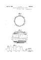
over the weld and is firmly welded to the adjacent pipe sections along the edges of the slots therein, and it may also be welded to the pipe sections along the end edges of the sleeve, if desired. The welds along the interior edges of the slots will connect the sleeve to both of the adjacent pipe sections on opposite sides of the butt weld across which they will extend, and the reenforcing sleeve if further Welded along its end edges will be united at these points to each of the adjacent pipe sections, thus not only reenforcing the butt weld, but making the joint the strongest part of the line, as the longitudinally extending portions of the reenforcing sleeve must be literally pulled apart before the ends of the pipe sections united by the butt weld can separate. In the accompanying drawings which illustrated one embodiment of my invention selected by me for purposes of illus- Fig. 1 is an elevation of portions of adjacent pipe sections having their butt welded together and reenforced in accordance with my present invention.
Fig. 2 represents a plan view of the cylindrical reenforcing member as it would appear if out and laid out in a horizontal plane.
Fig. 3 is an enlarged view partly in section of the welded and reenforced joint.
Fig. 4 represents a transverse section on the line H of Fig. 1 through the reinforcing sleeve and one o the pipe sections.
Fig. 5 is a perspective view of my reenforcing sleeve.
Fig. 6 is a plan view of a modified form of blank for the reenforcing sleeve.
In the drawings, P and P represent sections of pipe, the adjacent ends of which are butt welded as at W, in any desired manner, as for example by the oxy-acetylene welding process or by the electric arc welding process. In carrying out my present invention, I first form a reenforcing sleeve, indicated at a whole at S, and shown in detail detached in Fig. 5. This sleeve may be formed initially from a section of tube or pipe of Wrought metal, for example, having an internal diameter substantially the same as the external diameter of the pipe sections, P, P, or it may be formed by bending a flat piece of skelp into cylindrical form and welding the ends toether in a well known way. In the sleeve, S, two annular series of longitudinally disposed slots are formed, indicated at 1 and 1, the slots of each series extending from one end of the sleeve to a point near the opposite end, and the slots of one series being in staggered relation with the slots of the other series. This construction is very clearly illustrated in Fig. 2, which represents a plan view of the sleeve as it would appear if it was cut and laid out in a horizontal plane. The slots can be formed in any usual or desired manner, and if the sleeve is to be formed from a skelp, the slots may be stamped out or otherwise formed in the skelp before the ends are welded together, in which case the slotted skelp would have the appearance illustrated in Fig. 2.
The reenforcing sleeve when ready for use will therefore comprise a plurality of longitudinally disposed portions, 2, each connected at its opposite ends to an adjacent longitudinal portion, by the connecting portions, 3, at the inner ends of the slots. It will be seen that the zig-zag structure of the sleeve thus provided permits it to be expanded or contracted in diameter to insure its fitting the pipe sections with which it is used. The sleeve thus formed is slipped over one of the pipe sections and moved over the joint until it extends equally on opposite sides of the weld, TV, between the pipe sections in the manner indicated in Figs. 1 and 3. If the weld, W, as is usually the case, projects slightly beyond the outer face of the pipe sections, the ring can be forced over the weld and will expand its diameter sufiiciently to accommodate the weld. After the ring is placed in position with respect to the weld, the opposite ends of the longitudinally disposed portions, 2, and the connecting portions, 3, can be forced inwardly into contact with the pipe sections which they enclose, by the use of suitable clamps, and held while the welding operation which connects the reenforcing sleeve with the pipe sections is effected. lVhen in final position for welding the diameter of the sleeve will be greater adjacent to its longitudinal central portion than at its ends, and the longitudinal portions, 2. will be bent over the projecting portions of the annular weld, as clearly shown in Fig. 3. This will assist in the welding operation and insure better welding.
The sleeve, S, is welded to the pipe sections along the edges of each recess, 1 and 1, preferably by the use of the electric welding machine and the welding rod, and the formation of a fillet, which is indicated at 4. I
also prefer to weld the sleeve, S, to the pipe sections along the end edges of the sleeve in the same manner, the fillets so produced being indicated at 5, and being continuous with the fillets, 4, of the adjacent series of slots. It may be, however, that in some instances the welding of the sleeve, S, to the pipe sections along the end edges may be unnecessary and may therefore be dispensed with. It will be seen that each longitudinal portion, 2, of the reenforcing sleeve, S, is connected at its opposite sides for nearly its entire length,
by the fillets, 4, with the pipe sections, and that these fillets extend across the butt weld, \V, and firmly unite the sleeve, S, to the pipe sections on both sides of the ,weld, W. WVhen the fillets, 5, are formed, the sleeve, S, is additionally united to the pi e sections on opposite sides of the weld, W. bviously any force tending to separate the pipe sections, P, P from each other would have to disrupt the solid metal portions, 2, of the sleeve before separating the pipes, and therefore the welded joints will be greatly strengthened and will in fact be ordinarily stron er than the pipe section itself. between its ent ls.
It is to be noted that in carrying my invention into effect, no machine work is required on the pipe sections to prepare them to receive the reenforcing sleeves. The reenforcing sleeves can be made in quantity for the different sizes of standard pipe, as their yielding quality enables them to be expanded or contracted in diameter to compensate for any irregularities in the exterior surface of the pipe sections. Moreover, the reenforcing sleeves can be readily applied to the joints as the pipe sections are laid in a line and butt welded together. By the use of my invention the difliculties heretofore experienced with welded joints, causing serious loss by leakage of fluid, as natural and artificial gas, oil, etc, may be entirely obviated, and a practically impervious welded pipe line obtained. By the use of my invention it is practically impossible for the joints to break or crack at the butt weld between pipe sections, and these joints, as before stated, instead of being the weakest points in the line will in fact be the strongest points.
As previously stated the reenforcin ring may be made in the form of a blank rom a fiat skelp, having the form shown in Fig. 2, and the ends of the blank may be Welded together to form the ring. In Fig. 6, I have shown another form of blank which is conveniently made from a bar of wrought metal of any desired cross section, as round, square, or rectangular, which is bent into zig-zag form so as to form a flat blank having spaced parallel portions, 102, disposed transversely of the blank, and separated by slots or recesses, 101 and 101, each extending from one edge of the blank to a point near the other edge thereof, said parallel portions, 102, being each connected at one edge of the blank to the portion, 102, at one side thereof, and at the other edge of the blank to the portion, 102
:aeaaeee on the other side thereof, connecting portions being shown at 103.
This forms a blank substantially like that shown in Fig. 2, but without any waste of material such as would occur in forming the blank from a flat skelp, or forming the reenforcing ring from a tube and cutting out the portions to form the slots.
It will also be understood that where the skelp is prepared either inthe form shown in Fig. 2, or in the formshown in Fig. 6, it may be made up in the proper length to form a ring for any standard size of pipe, and welded at the factory, or the blanks may be shipped flat to the place of use and bent into ring tom and welded to form the reenforcin rings as needed. It will also be understoo that the blanks may be made in either of the forms shown and described and in lengths suitable for a plurality of reenforcin rings of the same diameter, or different diameters, and may be shipped flat to the place of use and cut into proper lengths, bent and welded. In this way the same blank may be used in the formation of reenforcing rin for several standard sizesof pipes, 1f des1red, and this may be found a convenience as where a line is being laid with branch lines of a different diameter.
What I claim and desire to secure by Letters Patent is 1. The herein described method of teenforcing the circular butt weld uniting adjacent pipe sections, which consists in surrounding the weld and marginal portions of the pipe sections with an integral wrought metal sleeve, capable of yielding to increase or decrease its diameter, compressing the end portions of the sleeve to bring them into contact with the pipe sections, and welding the sleeve to the pipe sections.
2. The herein described method of reen forcing the circular butt weld uniting adjacent pipe sections, which consists in surrounding the weld and marginal portions of the pipe sections with an integral wrought metal sleeve, capable of yielding to increase or decrease its diameter variably at difierent points in its length, compressing the end portions of the sleeve into contact with the pipe sections, and bending intermediate portions of the sleeve over projecting portions of the weld, and welding the sleeve to the pipe sections.
3. The herein described method of reenforcing the circular butt weld uniting adj acent 1pe sections, which consists in surrounding the weld and marginal portions of "the pipe sections with an integral wrought metal sleeve, capable of yielding to increase or decrease its diameter, said sleeve having spaced substantiall parallel longitudinal portions separated y slots having substantially parallel edges and extending alternately from opposite ends of the sleeve past the longitudinal center thereof and nearly to the opposite end, compressing the end portions of the sleeve to smaller; diameter than the can tral portion, and into contact with the pipe sections, and bending the longitudinal por= tions of the sleeve over projecting portions of the annular weld, and welding the sleeve to said pipe sections.
testimony whereof ll afiix my si atnre.
JAMES CL RK.
Priority Applications (1)
| Application Number | Priority Date | Filing Date | Title |
|---|---|---|---|
| US393298A US1853549A (en) | 1929-09-17 | 1929-09-17 | Method of reenforcing welded pipe joints |
Applications Claiming Priority (1)
| Application Number | Priority Date | Filing Date | Title |
|---|---|---|---|
| US393298A US1853549A (en) | 1929-09-17 | 1929-09-17 | Method of reenforcing welded pipe joints |
Publications (1)
| Publication Number | Publication Date |
|---|---|
| US1853549A true US1853549A (en) | 1932-04-12 |
Family
ID=23554129
Family Applications (1)
| Application Number | Title | Priority Date | Filing Date |
|---|---|---|---|
| US393298A Expired - Lifetime US1853549A (en) | 1929-09-17 | 1929-09-17 | Method of reenforcing welded pipe joints |
Country Status (1)
| Country | Link |
|---|---|
| US (1) | US1853549A (en) |
Cited By (9)
| Publication number | Priority date | Publication date | Assignee | Title |
|---|---|---|---|---|
| US2744429A (en) * | 1952-06-18 | 1956-05-08 | John S Seely | Tool for and method of forming a flow restriction in a conduit |
| US2930116A (en) * | 1955-12-06 | 1960-03-29 | Badger Mfg Company | Reinforcing ring for expansion joint and method of making same |
| US3512811A (en) * | 1968-01-22 | 1970-05-19 | Exxon Production Research Co | Pile-to-jacket connector |
| US4088372A (en) * | 1976-05-21 | 1978-05-09 | Deere & Company | Unitary wheel for industrial use |
| US4166942A (en) * | 1978-03-22 | 1979-09-04 | Bernhard Vihl | Reinforcing welds for fluid conduit wrapping for vessels |
| US5086854A (en) * | 1990-10-31 | 1992-02-11 | Roussy Raymond J | Drill pipes for rotary-vibratory drills |
| US5281778A (en) * | 1993-06-28 | 1994-01-25 | Midas International Corporation | Vehicular muffler with heat shield |
| US5477021A (en) * | 1990-02-24 | 1995-12-19 | Westfalia Separator | Centrifuge-drum disk |
| US11926001B2 (en) | 2013-03-12 | 2024-03-12 | Richard Humm | Welded fencing system with prefabricated connectors |
-
1929
- 1929-09-17 US US393298A patent/US1853549A/en not_active Expired - Lifetime
Cited By (9)
| Publication number | Priority date | Publication date | Assignee | Title |
|---|---|---|---|---|
| US2744429A (en) * | 1952-06-18 | 1956-05-08 | John S Seely | Tool for and method of forming a flow restriction in a conduit |
| US2930116A (en) * | 1955-12-06 | 1960-03-29 | Badger Mfg Company | Reinforcing ring for expansion joint and method of making same |
| US3512811A (en) * | 1968-01-22 | 1970-05-19 | Exxon Production Research Co | Pile-to-jacket connector |
| US4088372A (en) * | 1976-05-21 | 1978-05-09 | Deere & Company | Unitary wheel for industrial use |
| US4166942A (en) * | 1978-03-22 | 1979-09-04 | Bernhard Vihl | Reinforcing welds for fluid conduit wrapping for vessels |
| US5477021A (en) * | 1990-02-24 | 1995-12-19 | Westfalia Separator | Centrifuge-drum disk |
| US5086854A (en) * | 1990-10-31 | 1992-02-11 | Roussy Raymond J | Drill pipes for rotary-vibratory drills |
| US5281778A (en) * | 1993-06-28 | 1994-01-25 | Midas International Corporation | Vehicular muffler with heat shield |
| US11926001B2 (en) | 2013-03-12 | 2024-03-12 | Richard Humm | Welded fencing system with prefabricated connectors |
Similar Documents
| Publication | Publication Date | Title |
|---|---|---|
| US2098752A (en) | Structural section for aircraft | |
| US1921642A (en) | Pipe joint and method of forming same | |
| US1987341A (en) | Method of making pipe joints | |
| US1853549A (en) | Method of reenforcing welded pipe joints | |
| US1236145A (en) | Drill-stem and method of making the same. | |
| US605195A (en) | John birtwisle | |
| US1215969A (en) | Sheet-metal piston. | |
| US1760883A (en) | Structural joint and method of making the same | |
| US1696725A (en) | Drum, pipe, fittings, etc. | |
| US3248134A (en) | Reinforced welded joint | |
| US2369381A (en) | Welding ring | |
| US2451587A (en) | Pipe end and joint | |
| US1920449A (en) | Pipe joint | |
| US2219599A (en) | Method of joining intersecting tubular members | |
| US1838249A (en) | Method of welding pipe joints | |
| US1797151A (en) | Expansion joint | |
| US1886275A (en) | Method of joining pipe ends | |
| US1753638A (en) | Process of making couplings for sucker rods and the like | |
| US972119A (en) | Pipe-joint. | |
| US1887494A (en) | Making axle housings | |
| US2247173A (en) | Drilling collar | |
| US2258751A (en) | Method of making welded tool joints | |
| US2178858A (en) | Link body and method of making same | |
| US2380071A (en) | Welding band for pipe joints | |
| US1903852A (en) | Pipe joint |