US1853525A - Conveyer - Google Patents
Conveyer Download PDFInfo
- Publication number
- US1853525A US1853525A US465855A US46585530A US1853525A US 1853525 A US1853525 A US 1853525A US 465855 A US465855 A US 465855A US 46585530 A US46585530 A US 46585530A US 1853525 A US1853525 A US 1853525A
- Authority
- US
- United States
- Prior art keywords
- rails
- conveyer
- driver
- parallel
- chain
- Prior art date
- Legal status (The legal status is an assumption and is not a legal conclusion. Google has not performed a legal analysis and makes no representation as to the accuracy of the status listed.)
- Expired - Lifetime
Links
Images

Classifications
-
- B—PERFORMING OPERATIONS; TRANSPORTING
- B65—CONVEYING; PACKING; STORING; HANDLING THIN OR FILAMENTARY MATERIAL
- B65G—TRANSPORT OR STORAGE DEVICES, e.g. CONVEYORS FOR LOADING OR TIPPING, SHOP CONVEYOR SYSTEMS OR PNEUMATIC TUBE CONVEYORS
- B65G49/00—Conveying systems characterised by their application for specified purposes not otherwise provided for
- B65G49/02—Conveying systems characterised by their application for specified purposes not otherwise provided for for conveying workpieces through baths of liquid
- B65G49/04—Conveying systems characterised by their application for specified purposes not otherwise provided for for conveying workpieces through baths of liquid the workpieces being immersed and withdrawn by movement in a vertical direction
- B65G49/0409—Conveying systems characterised by their application for specified purposes not otherwise provided for for conveying workpieces through baths of liquid the workpieces being immersed and withdrawn by movement in a vertical direction specially adapted for workpieces of definite length
- B65G49/0413—Conveying systems characterised by their application for specified purposes not otherwise provided for for conveying workpieces through baths of liquid the workpieces being immersed and withdrawn by movement in a vertical direction specially adapted for workpieces of definite length arrangements for conveyance through the bath
- B65G49/0418—Conveying systems characterised by their application for specified purposes not otherwise provided for for conveying workpieces through baths of liquid the workpieces being immersed and withdrawn by movement in a vertical direction specially adapted for workpieces of definite length arrangements for conveyance through the bath chain or belt conveyors
Definitions
- This invention relates to conveyers in which a driver, usually a Hexible belt or chain, propels articles along a rail or guideway.
- the objects of the invention are to improve the construction of such conveyers by substituting simple standardized parts for the specially designed and relatively complicated conveyer and guideway units of the prior art, and to provide for quick and easy removal or insertion of standardized conveyer units in accordance with variations of the working requirements or the need for replacement of worn parts. .Further objects of the invention and features of construction will be made apparent in the course of the following description.
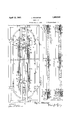
- Figure 1 is 'a plan view, partly broken away, of an electroplating tank equipped with my improved conveyer
- Figures 2 and 3 are enlarged detail views in elevation of a portion of a conveyer chain and adjacent parts;
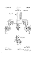
- a Figure 4 is a fragmentary transverse section on the line 4 4 of Figure 1;
- Figure 5 is an enlarged fragmentary View in plan, based upon Figure 1;
- Figure 6 is a horizontal section on line 6-6 of Figure 4.
- Figure 7 is an enlarged perspective view of a bridge member
- Figure 8. is a transverse sectional view on line 8-8 of Figure'l, the central portion only being shown;
- Figure 9 is a fragmentary view vased upon Figure 8, but showing the parts in a different relation.
- 1 designates a tank containing an electrolytic bath 2.
- Insulated brackets 3 secured to the side walls of the tank, support an anode bar 4, from which hooked anodes 5 depend into the bath.
- Hangers 8 are of chan'- nel form and have perforated end walls 11,
- an additional anode bar 15 is carried by hangers 16, which are secured to the irders 7 by means'of bolts 17 ( Figure 8).
- bus bar 18 has a lowerl hooked end 19, which is clamped around bar 15 by means of bolt 20.
- driving sprocket 21 and idler sprocket 22 are suspended from the girders 7.
- the mounting of the- Asprockets is shown in detail with reference to the driving sprocket in Figure 4.
- sprocket is clamped upon squared portion 28 of stub shaft 24 by means of nut 25.-
- the stub shaft is journalled in abed plate 26, which rests upon girders 7, and also carries a suitable driving mechanism which is indicated diagrammatically.
- An endless driver is provided, ⁇ which, in the illustrative embodiment shown, takes theform of a chain 27, preferably composed of separable links 28 to facilitate assembling and adjustments of the length of the chain.
- the conveyer belt is also preferably perfo rated at regular intervals, and in the embodi- -ment shown, the desired perforations are supplied by employing links of a rectangular ring form.
- Chain 27 is in mesh with sprockets 21 and 22, and is supported by bridge members 29 which pass through the links of the chain and rest at one end upon the outer rail or cathode bar 132 'and at the other end upon inner rails 30, which are secured to the hangers 8 ( Figure 8), and extend from sprocket straight course of the conveyer.
- the supporting path formed by the rails v3() is completed by shoulders 31 on the upper faces of the sprockets.
- the shoulders lie in the plane of the rails 30 and in 4 members, at their inner ends, are transferred from the rails to the shoulders when rounding the sprockets, while the sprocket teeth en age links 28 beneath the bridge members i re 4).
- the bridgg; members, as they slide along the rails will ca with themthe work supporting hooks 14.
- the outer rail or cathode bar 1S kept clean and perfect electrical contactbetween the bar and work supporting hooks is thus maintained.
- the number of bridge members emplo ed ma be varied at will to correspond to e num r of work supportin hooks employed at a 'ven time.v
- e outer ends 32 of t e bridge members are curved to conform to bar 13, and the inner ends are bifurcated to provide a pair of sup-k porting lugs 33 and a pair of vertical abutting faces 34.
- Thel 33 and abuttin faces 34 en ge rails 30 or s oulders 31, as t e case may at two points, one of which is in advance of the longitudinal axis of the bridge members, and the other of which is rearward thereof.
- the bridge members are of a crosssection which permits them to be readily passed through the links 28, thus facilitating insertion or withdrawal of the bridge members as required. ⁇
- This operation of inserting or withdrawing bridge members is conveniently rformed upon raising the chain in the middle of one of its straight courses, as shown in Figures 3 and 9.
- the bridge inembers are provided on their upper faces with slots 35 which snu ly engage the links 28 to d guide the chain an furnish additional resistice to pivotal movements of the bridge memrs.
- the operation of the apparatus has been suiciently indicated in the foregoing description and, in general, the operation doesnot differ from that of known electroplating apparatus.
- a conveyer comprising in combination a pair of paral el rails, a driver parallel to and between the rails and having spaced perforations, and traveling bridge members supported upon the rails and passing throu h the perforations, said bridge members longitudinally aligned guideways on their upper faces in which the driver lies.
- a coniiyer comprising in combination a pair of par el rails, a driving chain parallel to and between the rails and composed of prforate links, and traveling bridge memrs supported upon the rails and passing through the links, said bridge members having rooves on their upper faces engaging the links, the grooves being elongated in the direction of travel.
- a conveyer comprising in combination a air of parallel rails, a driver parallel to and tween the rails, traveling bridge members supported upon the rails and engaging thev driver, and articles to be conveyed movably supported upon one or both of said rails in the path of said bridge members.
- a conveyer comprisin in combination a pair of parallel rails, a river parallel to and between the rails, and a traveling bridge member supported upon the rails and engaging the driver, said bridge member vertically abutting at least one of the rails both forwardly and rearwardly of the point of engagement of the bridge member with the river.
- a conveyer comprising in combination a pair of parallel rails, a driver parallel to and between the rails, and a traveling bridge member supported upon the rails and engaging the driver, said bridge member having at each end a portion lying upon the adjacent rail for support, and a portion vertically abutting the rail to resist turning.
- a conveyer comprising in combination a pair of parallel rails, a driver arallel to and between the rails, and a travelin bridge member supported upon the rails an engageach .passing as aving ioo ing the driver, said bridge member having at each end a portion lying upon the adjacent rail for support, and a portion vertically abutting the rail to resist turning, the vertically abutting portion at one end being elongated in the direction of travel.
- a conveyer comprising in combination an endless driver mounted upon spaced wheels, an endless outer ra-il parallel to said driver, inner rails parallel to said driver and extending substantially throughout the spaces between said wheels, said wheels having flanges in the plane of and tangential to the inner rails, and traveling bridge members supported at their outer ends upon the outer rail and at their inner ends upon the inner rails or flanges, respectively.
- a conveyer comprising in combination an endless driver mounted upon spaced wheels, an endless outer rail parallel to said driver, inner rails parallel to said driver and extending substantially throughout the spaces between said wheels, said wheels having flanges in the plane of and tangential to the inner rails, and traveling bridge members supported at their outer ends upon the outer rail and at their inner ends upon the inner rails or flanges, respectively, the inner end of each bridge member having a portion 3o which lies upon the path formed by the inner rails and Wheel ianges and a portion which vertically abuts the inner rails and wheel ianges.
- a conveyer comprising in combination an endless driver mounted upon spaced wheels, an endless outer rail parallel to said driver, inner rails parallel to said driver and extending substantially throughout the spaces between said wheels, said wheels having ianges in the plane of and tangential to the inner rails, and traveling bridge members sup orted at their outer ends upon the outer ra1l and at their inner ends upon the inner rails or flanges, respectively, the inner end of each bridge member being bifurcated, each bifurcation having a portion which lies u on the path formed by the inner rails and wlheel flanges and a portion which vertically abuts the inner rails and wheel flan es.
Description
April l2, 1932. J, WACHTER 1,853,525
coNvEYER Filed July 7, 1950 3 Sheets-Sheet l u 3515 his abro/vn April 12, 1932. J. wAcHTER 1,853,525
CONVEYER Filed July 7, 193C 5 Sheets-Sheet 3 wventoz Patented Apr. 12, 1932 UNITED sTATEsPArsNr orf-'lcs JOSEPH WACHTm, OF NEWARK, NEW JERSEY, ABBIGNGB T MUNNING COMPANY, 0F VMATAWAN, NEW' JEBSEY, .L CORPORATION massiv Hanson-van' wnrxu- CONVEYEB Application led July 7, 1930.` Serial No. 485,855.
This invention relates to conveyers in which a driver, usually a Hexible belt or chain, propels articles along a rail or guideway.
The objects of the invention are to improve the construction of such conveyers by substituting simple standardized parts for the specially designed and relatively complicated conveyer and guideway units of the prior art, and to provide for quick and easy removal or insertion of standardized conveyer units in accordance with variations of the working requirements or the need for replacement of worn parts. .Further objects of the invention and features of construction will be made apparent in the course of the following description.
By way of illustrative embodiment there is shown in the drawings and hereinafter described a continuously operating electroplating apparatus; but the invention is capable of many other uses.
In the drawings,
Figure 1 is 'a plan view, partly broken away, of an electroplating tank equipped with my improved conveyer;
Figures 2 and 3 are enlarged detail views in elevation of a portion of a conveyer chain and adjacent parts; A Figure 4 is a fragmentary transverse section on the line 4 4 of Figure 1;
Figure 5 is an enlarged fragmentary View in plan, based upon Figure 1;
Figure 6 is a horizontal section on line 6-6 of Figure 4;
Figure 7 is an enlarged perspective view of a bridge member;
Figure 8.is a transverse sectional view on line 8-8 of Figure'l, the central portion only being shown; and
Figure 9 is a fragmentary view vased upon Figure 8, but showing the parts in a different relation.
Referring tothe drawings in detail, 1 designates a tank containing an electrolytic bath 2. Insulated brackets 3, secured to the side walls of the tank, support an anode bar 4, from which hooked anodes 5 depend into the bath. Frames 6, mounted on the end walls of the tank, support parallel angle gird- `to sprocket along each ers 7 upon which the remaining parts of the aplpIaratus are mounted.
through which machine screws-12 are tapped into the endless rail 13 which also serves `as a cathode bar (Figures 1 and .7 Work supporting hooks 14 are hung upon the rail or cathode bar 13 at intervals in position to be propelled along the -bar by the conveyer,
which is the subject of the present inventlon.
In the center of the tank an additional anode bar 15 is carried by hangers 16, which are secured to the irders 7 by means'of bolts 17 (Figure 8). bus bar 18 has a lowerl hooked end 19, which is clamped around bar 15 by means of bolt 20.
At opposite ends of the tank, driving sprocket 21 and idler sprocket 22 are suspended from the girders 7. The mounting of the- Asprockets is shown in detail with reference to the driving sprocket in Figure 4. The
sprocket is clamped upon squared portion 28 of stub shaft 24 by means of nut 25.- The stub shaft is journalled in abed plate 26, which rests upon girders 7, and also carries a suitable driving mechanism which is indicated diagrammatically.
An endless driver is provided,`\which, in the illustrative embodiment shown, takes theform of a chain 27, preferably composed of separable links 28 to facilitate assembling and adjustments of the length of the chain. The conveyer belt is also preferably perfo rated at regular intervals, and in the embodi- -ment shown, the desired perforations are supplied by employing links of a rectangular ring form. Chain 27 is in mesh with sprockets 21 and 22, and is supported by bridge members 29 which pass through the links of the chain and rest at one end upon the outer rail or cathode bar 132 'and at the other end upon inner rails 30, which are secured to the hangers 8 (Figure 8), and extend from sprocket straight course of the conveyer. The supporting path formed by the rails v3() is completed by shoulders 31 on the upper faces of the sprockets. The shoulders lie in the plane of the rails 30 and in 4 members, at their inner ends, are transferred from the rails to the shoulders when rounding the sprockets, while the sprocket teeth en age links 28 beneath the bridge members i re 4). It will be observed that the bridgg; members, as they slide along the rails, will ca with themthe work supporting hooks 14. The outer rail or cathode bar 1S kept clean and perfect electrical contactbetween the bar and work supporting hooks is thus maintained. The number of bridge members emplo ed ma be varied at will to correspond to e num r of work supportin hooks employed at a 'ven time.v
e outer ends 32 of t e bridge members are curved to conform to bar 13, and the inner ends are bifurcated to provide a pair of sup-k porting lugs 33 and a pair of vertical abutting faces 34. Thel 33 and abuttin faces 34 en ge rails 30 or s oulders 31, as t e case may at two points, one of which is in advance of the longitudinal axis of the bridge members, and the other of which is rearward thereof. With respect to the vertical abutting faces 34, this arrangement resists the turning tendenc of the bridge members under the forwar pull of the chain and the backward drag of the work supporting hooks and the separation of the faces 34 gives two plpints of contact with the shoulders 31 so at the alignment of the bridge members is maintained while they are rounding the sprockets. Se aration of the sup orting lugs 33 assists the ridge members w en passingfrom the rails 30 onto the shoulders 3l, since the rear lug will not leave the rail until the forward lug is securely seated upon the shoulder. L-sha guard plates 36 are shown and they may continued over the straight courses of the chain, but are not essential to Y the invention. For a greater part of their length the bridge members are of a crosssection which permits them to be readily passed through the links 28, thus facilitating insertion or withdrawal of the bridge members as required.` This operation of inserting or withdrawing bridge members is conveniently rformed upon raising the chain in the middle of one of its straight courses, as shown in Figures 3 and 9. The bridge inembers are provided on their upper faces with slots 35 which snu ly engage the links 28 to d guide the chain an furnish additional resistice to pivotal movements of the bridge memrs. The operation of the apparatus has been suiciently indicated in the foregoing description and, in general, the operation doesnot differ from that of known electroplating apparatus. It will be seen, however, that in contrast with known conveyer systems of this type, the present invention employs a few simple and separable parts whichare readily susoeptible of standardization. The outer rail 13, inner rails 30, and the conveyer chain, are of the simgilest possible construction, but
rform all o the required functions by virtue of the bridge members which support the chain and at t e same time engage and 'rol the work supporting hooks. -The c ain `is subjected to the least possible wearing friction, and the elaborate especially designed devices of the prior art for supporting the chain and engaging the articles to be conveyed are eliminated. The construction is open and free from pockets which would become clogged with dirt. I claim a pair of parallel rails, a drivin chain parallel to and between the rails an composed of perforate links, and travelin bridge members supplorted upon the rails an a w ole through the links.
2. A conveyer comprising in combination a pair of paral el rails, a driver parallel to and between the rails and having spaced perforations, and traveling bridge members supported upon the rails and passing throu h the perforations, said bridge members longitudinally aligned guideways on their upper faces in which the driver lies.
3. A coniiyer comprising in combination a pair of par el rails, a driving chain parallel to and between the rails and composed of prforate links, and traveling bridge memrs supported upon the rails and passing through the links, said bridge members having rooves on their upper faces engaging the links, the grooves being elongated in the direction of travel.
4. A conveyer comprising in combination a air of parallel rails, a driver parallel to and tween the rails, traveling bridge members supported upon the rails and engaging thev driver, and articles to be conveyed movably supported upon one or both of said rails in the path of said bridge members.
5. A conveyer comprisin in combination a pair of parallel rails, a river parallel to and between the rails, and a traveling bridge member supported upon the rails and engaging the driver, said bridge member vertically abutting at least one of the rails both forwardly and rearwardly of the point of engagement of the bridge member with the river.
6. A conveyer comprising in combination a pair of parallel rails, a driver parallel to and between the rails, and a traveling bridge member supported upon the rails and engaging the driver, said bridge member having at each end a portion lying upon the adjacent rail for support, and a portion vertically abutting the rail to resist turning.
7 A conveyer comprising in combination a pair of parallel rails, a driver arallel to and between the rails, and a travelin bridge member supported upon the rails an engageach .passing as aving ioo ing the driver, said bridge member having at each end a portion lying upon the adjacent rail for support, and a portion vertically abutting the rail to resist turning, the vertically abutting portion at one end being elongated in the direction of travel.
8. A conveyer comprising in combination an endless driver mounted upon spaced wheels, an endless outer ra-il parallel to said driver, inner rails parallel to said driver and extending substantially throughout the spaces between said wheels, said wheels having flanges in the plane of and tangential to the inner rails, and traveling bridge members supported at their outer ends upon the outer rail and at their inner ends upon the inner rails or flanges, respectively.
9. A conveyer comprising in combination an endless driver mounted upon spaced wheels, an endless outer rail parallel to said driver, inner rails parallel to said driver and extending substantially throughout the spaces between said wheels, said wheels having flanges in the plane of and tangential to the inner rails, and traveling bridge members supported at their outer ends upon the outer rail and at their inner ends upon the inner rails or flanges, respectively, the inner end of each bridge member having a portion 3o which lies upon the path formed by the inner rails and Wheel ianges and a portion which vertically abuts the inner rails and wheel ianges.
10. A conveyer comprising in combination an endless driver mounted upon spaced wheels, an endless outer rail parallel to said driver, inner rails parallel to said driver and extending substantially throughout the spaces between said wheels, said wheels having ianges in the plane of and tangential to the inner rails, and traveling bridge members sup orted at their outer ends upon the outer ra1l and at their inner ends upon the inner rails or flanges, respectively, the inner end of each bridge member being bifurcated, each bifurcation having a portion which lies u on the path formed by the inner rails and wlheel flanges and a portion which vertically abuts the inner rails and wheel flan es.
1 JOSEPH WAC TER.
Priority Applications (1)
| Application Number | Priority Date | Filing Date | Title |
|---|---|---|---|
| US465855A US1853525A (en) | 1930-07-07 | 1930-07-07 | Conveyer |
Applications Claiming Priority (1)
| Application Number | Priority Date | Filing Date | Title |
|---|---|---|---|
| US465855A US1853525A (en) | 1930-07-07 | 1930-07-07 | Conveyer |
Publications (1)
| Publication Number | Publication Date |
|---|---|
| US1853525A true US1853525A (en) | 1932-04-12 |
Family
ID=23849444
Family Applications (1)
| Application Number | Title | Priority Date | Filing Date |
|---|---|---|---|
| US465855A Expired - Lifetime US1853525A (en) | 1930-07-07 | 1930-07-07 | Conveyer |
Country Status (1)
| Country | Link |
|---|---|
| US (1) | US1853525A (en) |
-
1930
- 1930-07-07 US US465855A patent/US1853525A/en not_active Expired - Lifetime
Similar Documents
| Publication | Publication Date | Title |
|---|---|---|
| US4392434A (en) | Turbulent waterway | |
| GB2095642A (en) | Tiltable hanger apparatus for overhead conveyor assembly | |
| JP3223416U (en) | Sludge scraping device | |
| US5782340A (en) | Tapered side support for conveyor belts | |
| US1853525A (en) | Conveyer | |
| US2024846A (en) | Conveyer | |
| EP0339136B1 (en) | Horizontal circulation type parking apparatus | |
| US1920774A (en) | Trolley for conveyer systems | |
| US2609082A (en) | Hook conveyer | |
| US1043542A (en) | Conveyer. | |
| US2696308A (en) | Screening apparatus | |
| US1963460A (en) | Endless traveling water screen | |
| US1349557A (en) | Chain saw | |
| DE622747C (en) | Conveyor system for hanging loads with drag chain at the rising points | |
| US2288571A (en) | Conveyer | |
| CN102030172B (en) | Conveyor for food conveying | |
| US1871503A (en) | Cleaner for rollers of elevating graders | |
| US2800994A (en) | Mobile curvable conveyors | |
| US1800979A (en) | Tractor-belt drive | |
| US2162419A (en) | Mold conveyer | |
| US3289619A (en) | Traveling grates for incinerators | |
| US3198146A (en) | Travelling grates for incinerators | |
| DE650081C (en) | Device for producing moldings o. | |
| US1617615A (en) | Tread member for traction devices | |
| US1316831A (en) | Mabiwe way |