US1853524A - Manufacture of fishing nets - Google Patents
Manufacture of fishing nets Download PDFInfo
- Publication number
- US1853524A US1853524A US355651A US35565129A US1853524A US 1853524 A US1853524 A US 1853524A US 355651 A US355651 A US 355651A US 35565129 A US35565129 A US 35565129A US 1853524 A US1853524 A US 1853524A
- Authority
- US
- United States
- Prior art keywords
- net
- representing
- members
- deformable
- bars
- Prior art date
- Legal status (The legal status is an assumption and is not a legal conclusion. Google has not performed a legal analysis and makes no representation as to the accuracy of the status listed.)
- Expired - Lifetime
Links
Images
Classifications
-
- A—HUMAN NECESSITIES
- A01—AGRICULTURE; FORESTRY; ANIMAL HUSBANDRY; HUNTING; TRAPPING; FISHING
- A01K—ANIMAL HUSBANDRY; CARE OF BIRDS, FISHES, INSECTS; FISHING; REARING OR BREEDING ANIMALS, NOT OTHERWISE PROVIDED FOR; NEW BREEDS OF ANIMALS
- A01K75/00—Accessories for fishing nets; Details of fishing nets, e.g. structure
Definitions
- the invention relates to the manufacture of large fishing nets such as those used in trawl fishing, and more particularly to a skeleton frame adapted to represent on a,
- the present invention has for its object to provide an apparatus adapted to comply with the above requirements.
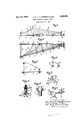
- Fig. 1 is a diagrammatic elevational view of an apparatus according to the invention.
- Fig. Q' is a correspondingplan view.
- Fig. 3 is-an end view.
- Fig. 4 is a cross section on the lines 44 ofFig.2.
- Figs. 5 to 8 show various details of construction. f t
- the apparatus comprises a rigid adjustable skeleton or frame which represents, on a smallscale a longitudinal half of the net. Obviously, the apparatus may alsocorrespond to the entire net, but a longitudinal half will generally serve the purpose in view.
- Said apparatus comprises a horizontal bar .1 corresponding to the longitudinal axis of the net. a horizontal bar 2 inclined fromthe first and corresponding to the usual side rope, or to the lateral outline of the net in plan view, the two bars being connected together by two parallelspa'cing members or cross members 8, 4. These different bars and cross a members are slotted and are secured together by bolts and nuts a, the slots affording the desired changes in the angle between the two bars 1Iand2, and in the distance between .bars 1 and 2 and cross members 3 and'4.
- an upright post p which is slidable in the slot of'said bar andcan be held in position by suitable means, for instance by a nut 72 (Fig. 3).
- a similar upright post 6 of less height is disposed at the other, end of said bar and is slidable on the same,
- sleeve 7 *(Fig. 6) each provided with a set screw 8 and a screw operated hook 9.
- measuring bars 10, 11, 12 secured to slides or cursors 0 2 which are provided with set screws d.
- the bar 1 carries a slide or cursor 13 provided with a screw operated hook 13
- a deformable rod 14 consisting of iron wire, for example, whose other end may be engaged in the hook 9 of the sleeve7 mounted on the upright 5.
- the said rod corresponds to the head rope of the net which is to be manufactured, and it maybe bent into any suitable curve.
- the said rod corresponds to the ground rope of the net, and it can be bent into the proper shape.
- a socket 16 of suitable height is mounted on the bolt a and spaces the ends of the rods1415 at the proper distance, corresponding to the height of the spreading slat or otterboard. V j
- Rods 14 and 15 may be provided with hooks 17 for attaching a number of strings 18whose otherends are attached to the hooks of a rod 19 which mayrberbent into any suitable shape and is mounted in like manner at the right hand end of the structure, between the inclined bar 2 and the small upright 6. It will be noted in Figures 1 and 2 that the apparatus thus provided with its strings stretched along the frame will represent 0n a small scale the general external shape.
- the dimensions of the pieces of netting are usually determined by taking one of the side ropes or thelateral outline-ofthe net as a base. and by making 'the measurements perpendicularly thereto. by Further, by measuring the corresponding heights of thestrings above the horizontal 1 plane, this will afiord all necessary data for properly shaping the differentparts of the net, and the numbers of meshes' can thus be accurately determined.
- the said apparatus issuscepti- -blefof numerous modifications itsform and construction; for instance, the rods 14,
- Nets having a greatvariety of forms may thus be. constructed, since it is feasible to change thelength of the net, its spread in width, its bulging in height, the length of the head rope, andthe like;
- the apparatus is to be used for the manufacture of a ground trawling net which is to be dragged upon the ground,but it may obvious ly be employed for nets adapted to operate in submerged floating condition, and in this event, since the lower sheet of the net is bulged out below the horizontal plane, the apparatus a tape line, or by rigid graduated bars slidable on the movable measuring bars 10, 11, 12, or upon the cross members 3 and 4, or the like.
- the various parts may carry graduated scales, as shown in' Figures 6 and S.
- the upper cord 18 representing the upper outline of thelnet in vertical projection may be replaced by a deformable rod consisting of iron wire, which may be curved into the proper shape. 7 Q Iron wires may also be substituted for the strings 18, and the wires ,orstrings may optionally rest upon one or more intermediate adjustable cross members, similar to the member 19, representing the rear pocket. The strings may also be'replaced by elastic cords.
- the apparatus is preferably mounted'upon'a pair of trestles or 'upona table provided with supporting cleats.
- An adjustable skeleton frame for use in the manufactureof fishing nets comprising number of frame members, means for adjustably connecting said frame members with each other 'whereby said frame is adapted to representat a smaller scale a portion at least of a fishing net of the desired shape, one of said fraineqmenibers representing substanti ally the lateral outline of one side of the net in plan View from the net rear pocket to the forward outer edge, and measuring members perpendicular to said last mentioned member and movable along the latter.
- An adjustable skeleton frame as claimed in claim 1 which further comprises a deformable member representing a portion at least of one of the ropes bounding the net mouth, a deformable member representing a )ortion at least ofthe cross-section of a rear portion of the net, and deformable means adapted to be connected with and stretched between said deformable members.
- An adjustable skeleton frame for use in frame members have measuring scales associated therewith.
- first rigid member representing the longitudinal axis of the net
- second rigid member representing substantially the lateral outline of one side of the net in plan View from the net rear pocket to the forward outer edge
- spacing members for adjustably connecting said rigid members a Vertical post of ad justable position along said first rigid memher, an attaching member of adjustable position along said post, a deformable member connected with said attaching member, and representing a portion of a rope bounding the net mouth
- means of adjustable position along said second rigid member for attach ing the end of said deformable member
- a deformable member representing a portion of the cross-section of the rear pocket
- An adjustable skeleton frame as claimed in claim 1. which further comprises a dcformable wire representing a portion at least of one of the ropes bounding the net mouth, a deformable wire representing a portion at least of the cross-section of the rear pocket, hooks spaced along said wires, and strings adapted to be attached to corresponding hooks of said wires.
Description
April 12, 1932- .1. a. J. A. VlGNERON ET AL 1,353,524
MANUFACTURE OF FISHING NETS Filed April 16, 1929 I NVNT QRS:
142 4 My!) (/6 -Ic u) T 0 R nr EYS Patented Apr. 12, 1932 UNITED STATES" PATENT OFFICE JEAN BAPTISTE J'OSEIPH'ALPHONSE VIGNERON, OF LA ROCHELLE, AND IPAU 'L HENRI FICHEUX, OF BOULOGNE-SUR-MER, FRANCE; SAID VIGNERON ASSIGNOR TO V. D.
LIMITED, or LONDON, ENGLAND MANUFACTIIRE OF FISHING NETS Application fired Apr i1 16, 1929, Serial N6. 355,651 a d intranet: a a, 1928. A
The invention relates to the manufacture of large fishing nets such as those used in trawl fishing, and more particularly to a skeleton frame adapted to represent on a,
and on which the necessary measurements may be made.
It has already been proposed to employ for the manufacture of fishing nets of a determined type, a skeleton frame which reproduces on a small scale the'general outline of the net, and upon which the various dimensions to be given to the different parts or pieces of netting of the net may be readily measured. However, this apparatus corresponds only to a single type of net, and only permits the construction of identical nets.
If the net manufacturer orthe ship owner desires to make a change in the type of the net in use, or to design a new type, a new skeleton frame must be provided for the purpose, and this represents a great expense and a loss of time.
In practice, the nets to be manufactured ofier considerable differences according to the power of the trawler, the different varieties offish to be captured, the height at which the net is'to operate (on the ground, at the surface, or in submerged condition), and other factors. V
It is thus evident that a net manufacturer who is obligedto comply with the demands of his various customers in the fishing trade and is thus occupied with continual improvements in the form of the nets, as well as the ship-owner who possesses boats of dif ferent tonnages adapted for various fishing operations, shouldbe provided withan apparatus which can be'readily transformed in such manner as to correspond to a great variety of nets, and the manufacturer or shipowner will be thus enabled to study the different modifications required fora given net, and also to devise new types, and in all cases,
to rapidly determine the shape and size of the parts'of the net which is to be manufactured. I I o The present invention has for its object to provide an apparatus adapted to comply with the above requirements.
In the accompanying drawings, which are given by way of example:
Fig. 1 is a diagrammatic elevational view of an apparatus according to the invention.
Fig. Q'is a correspondingplan view. Fig. 3 is-an end view. Fig. 4: is a cross section on the lines 44 ofFig.2.
Figs. 5 to 8 show various details of construction. f t
In the form of construction shown in the drawings, the apparatus comprises a rigid adjustable skeleton or frame which represents, on a smallscale a longitudinal half of the net. Obviously, the apparatus may alsocorrespond to the entire net, but a longitudinal half will generally serve the purpose in view. I I
Said apparatus comprises a horizontal bar .1 corresponding to the longitudinal axis of the net. a horizontal bar 2 inclined fromthe first and corresponding to the usual side rope, or to the lateral outline of the net in plan view, the two bars being connected together by two parallelspa'cing members or cross members 8, 4. These different bars and cross a members are slotted and are secured together by bolts and nuts a, the slots affording the desired changes in the angle between the two bars 1Iand2, and in the distance between .bars 1 and 2 and cross members 3 and'4.
Upon the bar 1 is mounted an upright post p which is slidable in the slot of'said bar andcan be held in position by suitable means, for instance by a nut 72 (Fig. 3). A similar upright post 6 of less height is disposed at the other, end of said bar and is slidable on the same, Upon the respective upright posts are mounted sleeve 7 *(Fig. 6) each provided with a set screw 8 and a screw operated hook 9. Upon the inclined bar 2 are slidably mounted measuring bars 10, 11, 12 secured to slides or cursors 0 2) which are provided with set screws d. Betweenthe uprights 56, the bar 1 carries a slide or cursor 13 provided with a screw operated hook 13 At the point of junction of the inclined bar 2- and the cross member 3 may be secured one end of a deformable rod 14, consisting of iron wire, for example, whose other end may be engaged in the hook 9 of the sleeve7 mounted on the upright 5. The said rod corresponds to the head rope of the net which is to be manufactured, and it maybe bent into any suitable curve. A similar rod 15,
, also of iron wire, may be secured at the said 1' point of junction at one end, its other end; being secured by'the hook 13 of the slide 13.'
The said rod corresponds to the ground rope of the net, and it can be bent into the proper shape. A socket 16 of suitable height is mounted on the bolt a and spaces the ends of the rods1415 at the proper distance, corresponding to the height of the spreading slat or otterboard. V j
the net to be constructed. i g V The said apparatus isutilized' in the following manner:
' The inclination between the bars 1 and 2,
and the distance between the uprights 5 and.
6 are first adjusted, The rods 14, 15 and 19 corresponding to the head rope, ground rope and rear end ofthe net, are then properly I curved into shape; the strings 18 are stretched between the corresponding hooks 1770f said rods. Thebars 10, 11, 12 arenow displaced along the inclined bar 2, so that the distances can be measured perpendicularly to -said bar.
Itshould be observed thatthe dimensions of the pieces of netting are usually determined by taking one of the side ropes or thelateral outline-ofthe net as a base. and by making 'the measurements perpendicularly thereto. by Further, by measuring the corresponding heights of thestrings above the horizontal 1 plane, this will afiord all necessary data for properly shaping the differentparts of the net, and the numbers of meshes' can thus be accurately determined. it Obviously, the said apparatus issuscepti- -blefof numerous modifications itsform and construction; for instance, the rods 14,
15, 19 representing respectively the head rope, the ground rope and the outline of the rear pocket, may consist of flexible wooden bars or rods.
Instead of using slotted bars to constitute the horizontal frame, provision may be made of solid or tubular elements, of the type shown in Fig. 8; in this case, suitable collars 20 are mounted on the tubes and are provided with set screws 21. The adjustable junction betweenthe elements is made for instance by means of double sleeves 22 provided with set screws. I v
Nets having a greatvariety of forms may thus be. constructed, since it is feasible to change thelength of the net, its spread in width, its bulging in height, the length of the head rope, andthe like;
In the drawings, it is supposed that the apparatus is to be used for the manufacture of a ground trawling net which is to be dragged upon the ground,but it may obvious ly be employed for nets adapted to operate in submerged floating condition, and in this event, since the lower sheet of the net is bulged out below the horizontal plane, the apparatus a tape line, or by rigid graduated bars slidable on the movable measuring bars 10, 11, 12, or upon the cross members 3 and 4, or the like. The various parts may carry graduated scales, as shown in'Figures 6 and S.
' The upper cord 18 representing the upper outline of thelnet in vertical projection may be replaced by a deformable rod consisting of iron wire, which may be curved into the proper shape. 7 Q Iron wires may also be substituted for the strings 18, and the wires ,orstrings may optionally rest upon one or more intermediate adjustable cross members, similar to the member 19, representing the rear pocket. The strings may also be'replaced by elastic cords. To renderthe differentparts of the apparatus accessible, and in particular the'nuts of the. bolts a and the nuts I), the apparatus is preferably mounted'upon'a pair of trestles or 'upona table provided with supporting cleats.
Having now described our invention what wetlaiin as new and desire to secure by Letters Patent is: I V r 1. An adjustable skeleton frame for use in the manufactureof fishing nets, comprising number of frame members, means for adjustably connecting said frame members with each other 'whereby said frame is adapted to representat a smaller scale a portion at least of a fishing net of the desired shape, one of said fraineqmenibers representing substanti ally the lateral outline of one side of the net in plan View from the net rear pocket to the forward outer edge, and measuring members perpendicular to said last mentioned member and movable along the latter.
2. An adjustable skeleton frame as claimed in claim 1, which further comprises a deformable member representing a portion at least of one of the ropes boundingthe net mouth.
3. An adjustable skeleton frame as claimed in claim 1, which further comprises a deformable member representing a portion at least of the head rope.
4. An adjustable skeleton frame as claimed in claim 1, which further comprises a deformable member representing a portion at least of the cross-section of a rear portion of the net.
5. An adjustable skeleton frame as claimed in claim 1, which further comprises a deformable member representing a portion at least of one of the ropes bounding the net mouth, a deformable member representing a )ortion at least ofthe cross-section of a rear portion of the net, and deformable means adapted to be connected with and stretched between said deformable members.
6. An adjustable skeleton frame for use in frame members have measuring scales associated therewith.
10. An adjustable skeleton frame as claimed in claim 1, wherein a number of said rigid frame members are made of slotted bars, some of said connecting means slidably engaging two slots of adj acent bars.
In testimony whereof we have signed our names to this specification.
JEAN BAPTISTE JOSEPH ALPHONSE VIGNERON. 7 PAUL HENRI FICHEUX.
the manufacture of fishing nets, comprising a first rigid member representing the longitudinal axis of the net, :1 second rigid member representing substantially the lateral outline of one side of the net in plan View from the net rear pocket to the forward outer edge, spacing membersfor adjustably connecting said rigid members a Vertical post of ad justable position along said first rigid memher, an attaching member of adjustable position along said post, a deformable member connected with said attaching member, and representing a portion of a rope bounding the net mouth, means of adjustable position along said second rigid member for attach ing the end of said deformable member, a deformable member representing a portion of the cross-section of the rear pocket, means for connecting said latter memberto said rigid members and deformable means connected to and stretched between said deformable members.
7. An adjustable skeleton frame as claimed in claim 1, which further comprises a deformable wire representing a portion at least of one of the ropes bounding the net mouth.
8. An adjustable skeleton frame as claimed in claim 1. which further comprises a dcformable wire representing a portion at least of one of the ropes bounding the net mouth, a deformable wire representing a portion at least of the cross-section of the rear pocket, hooks spaced along said wires, and strings adapted to be attached to corresponding hooks of said wires. I
9. An adjustable skeleton frame as claimed in claim 1, wherein a number of said rigid
Applications Claiming Priority (1)
| Application Number | Priority Date | Filing Date | Title |
|---|---|---|---|
| FR1853524X | 1928-05-07 |
Publications (1)
| Publication Number | Publication Date |
|---|---|
| US1853524A true US1853524A (en) | 1932-04-12 |
Family
ID=9681673
Family Applications (1)
| Application Number | Title | Priority Date | Filing Date |
|---|---|---|---|
| US355651A Expired - Lifetime US1853524A (en) | 1928-05-07 | 1929-04-16 | Manufacture of fishing nets |
Country Status (1)
| Country | Link |
|---|---|
| US (1) | US1853524A (en) |
Cited By (1)
| Publication number | Priority date | Publication date | Assignee | Title |
|---|---|---|---|---|
| US2880510A (en) * | 1955-02-03 | 1959-04-07 | Robert H Ray Company | Apparatus for locating the position and dip of reflecting strata and for plotting ray paths |
-
1929
- 1929-04-16 US US355651A patent/US1853524A/en not_active Expired - Lifetime
Cited By (1)
| Publication number | Priority date | Publication date | Assignee | Title |
|---|---|---|---|---|
| US2880510A (en) * | 1955-02-03 | 1959-04-07 | Robert H Ray Company | Apparatus for locating the position and dip of reflecting strata and for plotting ray paths |
Similar Documents
| Publication | Publication Date | Title |
|---|---|---|
| US1550944A (en) | Stand for cameras and the like | |
| US1853524A (en) | Manufacture of fishing nets | |
| US2634740A (en) | Adjustable awning | |
| DE850936C (en) | Inflatable mattress that can be converted into an armchair | |
| US1411895A (en) | Bag rack | |
| US879959A (en) | Means for supporting climbing-plants. | |
| US2249382A (en) | Fishing paraphernalia | |
| US1860390A (en) | Adjustable plant stand | |
| CN207909183U (en) | A kind of adjustable rice and kernel fish (Shrimp) fry counter | |
| DE423907C (en) | Spreader stick for fish traps | |
| US733792A (en) | Metallic post. | |
| CN214174802U (en) | Portable plant standard is shot and is shot background board | |
| CN112155272B (en) | Collapsible measuring device is used in dress designing | |
| DE126195C (en) | ||
| DE2749909C2 (en) | ||
| SU29603A1 (en) | Lekalo | |
| DE378441C (en) | Apparatus for indoor gymnastics | |
| DE402191C (en) | Tab shift for precision scales | |
| US2035038A (en) | Streamer adapted for towing by aircraft | |
| DE430117C (en) | Holder with screw-in leg for the curtain rods and cord guide rings of curtain pulling devices | |
| US1880860A (en) | Mattress | |
| CH182022A (en) | Clothes horse. | |
| JPH0356414B2 (en) | ||
| DE662682C (en) | Bellyless bottom trawl | |
| GB315654A (en) | Improvements in hay racks and the like |