US1853518A - Skimmer - Google Patents
Skimmer Download PDFInfo
- Publication number
- US1853518A US1853518A US489416D US48941630D US1853518A US 1853518 A US1853518 A US 1853518A US 489416 D US489416 D US 489416D US 48941630 D US48941630 D US 48941630D US 1853518 A US1853518 A US 1853518A
- Authority
- US
- United States
- Prior art keywords
- skimmer
- pouring
- ladle
- frame
- metal
- Prior art date
- Legal status (The legal status is an assumption and is not a legal conclusion. Google has not performed a legal analysis and makes no representation as to the accuracy of the status listed.)
- Expired - Lifetime
Links
Images


Classifications
-
- F—MECHANICAL ENGINEERING; LIGHTING; HEATING; WEAPONS; BLASTING
- F27—FURNACES; KILNS; OVENS; RETORTS
- F27D—DETAILS OR ACCESSORIES OF FURNACES, KILNS, OVENS, OR RETORTS, IN SO FAR AS THEY ARE OF KINDS OCCURRING IN MORE THAN ONE KIND OF FURNACE
- F27D3/00—Charging; Discharging; Manipulation of charge
- F27D3/15—Tapping equipment; Equipment for removing or retaining slag
- F27D3/1545—Equipment for removing or retaining slag
-
- B—PERFORMING OPERATIONS; TRANSPORTING
- B22—CASTING; POWDER METALLURGY
- B22D—CASTING OF METALS; CASTING OF OTHER SUBSTANCES BY THE SAME PROCESSES OR DEVICES
- B22D43/00—Mechanical cleaning, e.g. skimming of molten metals
- B22D43/001—Retaining slag during pouring molten metal
Definitions
- This invention relates to a method of and apparatus for skimming or removing surface impurities from molten metals such as iron and steel, and the primary object in view is to provide a convenient and effective method and means whereby impurities such as slag, kish and the like that may be floating on the surface of the metal in a ladle or analogous container prior to pouring may be retained in the ladle after the pouring operation and dumped into a separate container or disposed of in any desired manner.
- the method consists, essentially, in pouring the molten metal from a container through a restricted outlet, and interposing an obstruction to the top surface portion of the metal, while pouring, to engage and retain the impurities in the container.
- FIG. 1 is a topplan View of the improved skimming apparatus in operative position on a pouring ladle.
- Figure 2 is a central sectional elevation thereof.
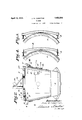
- Figure 3 a View in sideelevation, showing the ladle with the skimmer in position thereon in extreme tilted position.
- FIGS 4, 5 and 6 are detail sectional views taken, respectively, on the lines IVIV, V V, and VIVI of Figure 2.
- the reference numeral 5 designates a top pouring ladle of the usual type,'having pouring spouts 6 and 6, and trunnions 7, by means of Which it may be hooked and suspended from an overhead crane, the crane hook being indicated at 8, Fig. 3.
- skimming apparatus used in carrying out the present method con- I sists essentially of a skimmer plate 9, which may be formed of suitable heat-resisting material or made of cast metal and lined with refractory material, said plate being formed with a cored-out portion 10 terminating on with set screws 13, a supporting shaft 14: be-
- the length of the shaft is such as each side of the plate in hubs 1:2 providedv to accommodate ladies of varying diameters.
- Theworking edge of the skimmer plate 9 is formed with a retaining portion or is flanged as at 15 and said edge is contoured to conform to the contour of the inner refractory wall or lining of the ladle adjacent the spouts 6, to thus enable it to fit closely to said wall.
- the shaft 1a is formed with keyways and mounted in holders 16, which are formed with cooperating key seats, said holders beingsuit-- ably secured to side frame members or beams 17, the rear extremities of which have secured thereto, by means of angle plates 18, beams 18', which extend down over the sides of the ladle when the skimmer is positioned thereon.
- a latch bar or analogous member 19 is secured to the angle beams 18, said latch bar being adapted to catch under the lip of the pouring spout of the ladle when the skimmer is applied thereto.
- a hanger 23 is secured to the side beams17, said hanger being reinforced by anchorposts 24.
- the hanger 23 is adapted to receive the auX- iliary crane hook for the skimmer apparatus, indicated at 25, and to prevent the skimmer apparatus from turning or becoming dis-V placed angularly while suspended and thus render the positioning operationmore difficult, angle plates 26 are secured to the'hanger,
- the improved skimmer is portable and is adapted to be placed inoperative position on the ladle at the time of pouring.
- the ladle In the operation of the skimmer, the ladle is filled with molten metal from the furnace, the mixer or other source of supply and transferred to its pouring position, and either before moving the ladle or after it has been transferred to pouring position, the skimmer opposite that from which'themetal is being poured while the latch 20 is engaged under the band 22. While the skimmer is in suspended position, the positioning operation may be readily performed, the angle plates 26 preventing the skimmer from turning on the crane hookQ The skimmer plate 9-should be adjusted to the most efiective position, or so that its working edge will prevent thesur- 7 face inpurities from passing off with the molten metal.
- the ladle is gradually tilted to pour the metal from the'spout, the flanged edge of the skimmer engaging the slag, kish and like impurities and holding them back so that they will not pass from the ladle.
- the nnpurities may be 7 dumped or otherwise disposed of.
- a portable skimmer for use with pouring ladles for molten metal having pouring spouts at diametrically opposite points, said skimmer comprising a supporting frame adapted to be bridged across the'top of the ladle and having means cooperating with one of the ladle pouring spouts for retaining the frame in position when said ladle is tiltedto pouring position, and a skimmer plate adjustably mounted on said frame for move ment into and out of the ladle.
- skimmer comprising a supporting frame adapted to be'bridged across the top of the ladle and having means cooperating withone of the ladle pouring spouts for retaining the frame in position when said ladle is tiltedto pouring position, a skimmer plate adjustably mounted on said frame for movement into and out of the ladle, and means'for lockthe frame in position when said ladle is tilted .to pouring position, a shaft fixedly mounted in said frame, a skimmer plate mounted on said shaft and adapted to be rotated about said shaft to adjust said plate relative to said ladle, and means for locking said plate on said shaft.
- A'portable skimmer of the class specified comprising a skimmer plate, a supporting frame therefor, a hangersecured to said frame to provld'e for suspending the skimmer from an overhead crane hook, and
- a portable skimmer for use With pouring ladles for molten metal having pouring spouts at diametrically opposite points, said skimmer comprising a supporting frame adapted to be bridged across the top ofthe metal and having means cooperating with one of the 1adle;pouring spoutsfor retaining plateagainst movement relative to said
Description
April 12, 1932. w, FQRSYTHE 1,853,518
SKIMMER Filed Oct. 17, 1930 3 Sheets-Sheet 2 v 022507; JOHN 14 fB/QSYT E,
April 12, 1932. J. w. FORSYTHE SKIMMER Filed Oct. 17, 1930 5 Sheets-Sheet 5 JOHN W Foes YTHE, W
Patented Apr. 12, 1932 UNITED STATES JOHN W. FORSY'IHE, OF WILKINSBURG, PENNSYLVANIA SKIMMER Application filed. October 17, 1930. Seria1 No. 489,416.
This invention relates to a method of and apparatus for skimming or removing surface impurities from molten metals such as iron and steel, and the primary object in view is to provide a convenient and effective method and means whereby impurities such as slag, kish and the like that may be floating on the surface of the metal in a ladle or analogous container prior to pouring may be retained in the ladle after the pouring operation and dumped into a separate container or disposed of in any desired manner.
The method consists, essentially, in pouring the molten metal from a container through a restricted outlet, and interposing an obstruction to the top surface portion of the metal, while pouring, to engage and retain the impurities in the container.
In the drawings:
m Figure 1 is a topplan View of the improved skimming apparatus in operative position on a pouring ladle.
Figure 2 is a central sectional elevation thereof.
Figure 3 a View in sideelevation, showing the ladle with the skimmer in position thereon in extreme tilted position.
Figures 4, 5 and 6 are detail sectional views taken, respectively, on the lines IVIV, V V, and VIVI of Figure 2. V
The reference numeral 5 designates a top pouring ladle of the usual type,'having pouring spouts 6 and 6, and trunnions 7, by means of Which it may be hooked and suspended from an overhead crane, the crane hook being indicated at 8, Fig. 3.
The preferred type of skimming apparatus used in carrying out the present method con- I sists essentially of a skimmer plate 9, which may be formed of suitable heat-resisting material or made of cast metal and lined with refractory material, said plate being formed with a cored-out portion 10 terminating on with set screws 13, a supporting shaft 14: be-
thereon. The length of the shaft is such as each side of the plate in hubs 1:2 providedv to accommodate ladies of varying diameters.
Theworking edge of the skimmer plate 9 is formed with a retaining portion or is flanged as at 15 and said edge is contoured to conform to the contour of the inner refractory wall or lining of the ladle adjacent the spouts 6, to thus enable it to fit closely to said wall. I
The shaft 1a is formed with keyways and mounted in holders 16, which are formed with cooperating key seats, said holders beingsuit-- ably secured to side frame members or beams 17, the rear extremities of which have secured thereto, by means of angle plates 18, beams 18', which extend down over the sides of the ladle when the skimmer is positioned thereon.
To prevent the skimmer from becoming displaced while pouring, a latch bar or analogous member 19 is secured to the angle beams 18, said latch bar being adapted to catch under the lip of the pouring spout of the ladle when the skimmer is applied thereto.
As an additional precaution against slip- V ping of the skimmer while pouring, particuiliary trolley, and to provide for this method of transportation, a hanger 23 is secured to the side beams17, said hanger being reinforced by anchorposts 24.
The hanger 23 is adapted to receive the auX- iliary crane hook for the skimmer apparatus, indicated at 25, and to prevent the skimmer apparatus from turning or becoming dis-V placed angularly while suspended and thus render the positioning operationmore difficult, angle plates 26 are secured to the'hanger,
said angle plates being adapted to bear against said hook 25. j I
The improved skimmer is portable and is adapted to be placed inoperative position on the ladle at the time of pouring.
In the operation of the skimmer, the ladle is filled with molten metal from the furnace, the mixer or other source of supply and transferred to its pouring position, and either before moving the ladle or after it has been transferred to pouring position, the skimmer opposite that from which'themetal is being poured while the latch 20 is engaged under the band 22. While the skimmer is in suspended position, the positioning operation may be readily performed, the angle plates 26 preventing the skimmer from turning on the crane hookQ The skimmer plate 9-should be adjusted to the most efiective position, or so that its working edge will prevent thesur- 7 face inpurities from passing off with the molten metal.
After the skimmer is placed in operative position, the ladle is gradually tilted to pour the metal from the'spout, the flanged edge of the skimmer engaging the slag, kish and like impurities and holding them back so that they will not pass from the ladle. After the metal has been poured, the nnpurities may be 7 dumped or otherwise disposed of.
What is claimed'as new is: V
l. A portable skimmer for use with pouring ladles for molten metal having pouring spouts at diametrically opposite points, said skimmer comprising a supporting frame adapted to be bridged across the'top of the ladle and having means cooperating with one of the ladle pouring spouts for retaining the frame in position when said ladle is tiltedto pouring position, and a skimmer plate adjustably mounted on said frame for move ment into and out of the ladle.
2. Aport-able skimmer for use with pouring ladies for molten metal havingpouring spouts at diametrically opposite p oints,said
' skimmer comprising a supporting frame adapted to be'bridged across the top of the ladle and having means cooperating withone of the ladle pouring spouts for retaining the frame in position when said ladle is tiltedto pouring position, a skimmer plate adjustably mounted on said frame for movement into and out of the ladle, and means'for lockthe frame in position when said ladle is tilted .to pouring position, a shaft fixedly mounted in said frame, a skimmer plate mounted on said shaft and adapted to be rotated about said shaft to adjust said plate relative to said ladle, and means for locking said plate on said shaft.
4. A portableskimmer for usewith pouring ladles for molten" metal having "pouring spouts at opposite sides thereof,vcomprising a supporting frame having a latch device adapted to engage under one of the spouts of --the ladle to prevent displacement of the latchportion adapted to engage under one ,1
of the spouts ofthe metal to prevent displacement of said frame when the ladleis tilted to pouring position, a shaft carried by said frame, and a skimmerplate ournaled on said shaft adaptedtobe positioned with its working edge in cooperative relation with the spout of the ladle into which the metal is to be poured, and means for locking said skimmer shaf 6. A'portable skimmer of the class specified, comprising a skimmer plate, a supporting frame therefor, a hangersecured to said frame to provld'e for suspending the skimmer from an overhead crane hook, and
angle plates secured to said hanger, said plates being. spaced to permit said crane hook to move therebetween, and being adapted to bear against said hook toprevent angular displacement of said skimmer relative to'said hook. V
In 'WliIlQSS'WllGI'BQf, I have hereunto set my'hand.
JOHN FORSYTHE.
ing said skimmer plate in its adjusted positions.
3 A portable skimmer for use With pouring ladles for molten metal having pouring spouts at diametrically opposite points, said skimmer comprising a supporting frame adapted to be bridged across the top ofthe metal and having means cooperating with one of the 1adle;pouring spoutsfor retaining plateagainst movement relative to said
Priority Applications (1)
| Application Number | Priority Date | Filing Date | Title |
|---|---|---|---|
| US489416D US1853518A (en) | 1930-10-17 | 1930-10-17 | Skimmer |
Applications Claiming Priority (1)
| Application Number | Priority Date | Filing Date | Title |
|---|---|---|---|
| US489416D US1853518A (en) | 1930-10-17 | 1930-10-17 | Skimmer |
Publications (1)
| Publication Number | Publication Date |
|---|---|
| US1853518A true US1853518A (en) | 1932-04-12 |
Family
ID=23943767
Family Applications (1)
| Application Number | Title | Priority Date | Filing Date |
|---|---|---|---|
| US489416D Expired - Lifetime US1853518A (en) | 1930-10-17 | 1930-10-17 | Skimmer |
Country Status (1)
| Country | Link |
|---|---|
| US (1) | US1853518A (en) |
Cited By (3)
| Publication number | Priority date | Publication date | Assignee | Title |
|---|---|---|---|---|
| US2494270A (en) * | 1945-08-11 | 1950-01-10 | Virgil H Todd | Crucible skimmer |
| WO1992005000A1 (en) * | 1990-09-17 | 1992-04-02 | Doehler-Jarvis Limited Partnership | Area displacement device for molten metal ladle |
| US5544867A (en) * | 1995-03-13 | 1996-08-13 | Neyer; Richard H. | Apparatus and process for transporting molten metal |
-
1930
- 1930-10-17 US US489416D patent/US1853518A/en not_active Expired - Lifetime
Cited By (3)
| Publication number | Priority date | Publication date | Assignee | Title |
|---|---|---|---|---|
| US2494270A (en) * | 1945-08-11 | 1950-01-10 | Virgil H Todd | Crucible skimmer |
| WO1992005000A1 (en) * | 1990-09-17 | 1992-04-02 | Doehler-Jarvis Limited Partnership | Area displacement device for molten metal ladle |
| US5544867A (en) * | 1995-03-13 | 1996-08-13 | Neyer; Richard H. | Apparatus and process for transporting molten metal |
Similar Documents
| Publication | Publication Date | Title |
|---|---|---|
| US1853518A (en) | Skimmer | |
| US2079872A (en) | Apparatus for the conversion of metal | |
| JP4065983B2 (en) | Ladle with lid | |
| US623073A (en) | Means for transferring steel from vessels or furnaces to molds | |
| US3861571A (en) | Ladle flow control safety device for continuous casting machine | |
| FI56495C (en) | OVER ANCHORING FOR METAL PROTECTION WITH METAL I IN STRAENGGJUTNINGSKOKILL | |
| US1347984A (en) | Hot-metal ladle-car | |
| US2042037A (en) | Tilting ladle | |
| US2880989A (en) | Apparatus for discharging molten metal | |
| US3486745A (en) | Metallurgical furnace construction | |
| US3495812A (en) | Apparatus for removing and handling covers for converters or crucibles and for renewing the refractory lining | |
| US2102823A (en) | Combination furnace | |
| RU2100143C1 (en) | Gear for preparation of metallurgical ladle | |
| US1058158A (en) | Treatment of slag. | |
| US2910746A (en) | Tilting ladle | |
| US3087212A (en) | Hinged heat shield for metal teeming ladle bottoms | |
| US3200453A (en) | Rigging for tilting ladles | |
| JPS6138767Y2 (en) | ||
| US3791638A (en) | Metal pouring organization | |
| CN108296471A (en) | A kind of multifunctional steel wire cord lock tool teeming stage and its pouring procedure | |
| SU984669A1 (en) | Apparatus for pouring metal | |
| SU353788A1 (en) | INSTALLATION FOR STEEL CASTING | |
| US3292916A (en) | Metal degassing apparatus | |
| US1446031A (en) | Ladle hanger | |
| RU1771876C (en) | Method of bottom casting of steel |