US1853482A - Washing machine drive - Google Patents
Washing machine drive Download PDFInfo
- Publication number
- US1853482A US1853482A US446983A US44698330A US1853482A US 1853482 A US1853482 A US 1853482A US 446983 A US446983 A US 446983A US 44698330 A US44698330 A US 44698330A US 1853482 A US1853482 A US 1853482A
- Authority
- US
- United States
- Prior art keywords
- rack bar
- clutch
- pinion
- shaft
- washing machine
- Prior art date
- Legal status (The legal status is an assumption and is not a legal conclusion. Google has not performed a legal analysis and makes no representation as to the accuracy of the status listed.)
- Expired - Lifetime
Links
Images
Classifications
-
- D—TEXTILES; PAPER
- D06—TREATMENT OF TEXTILES OR THE LIKE; LAUNDERING; FLEXIBLE MATERIALS NOT OTHERWISE PROVIDED FOR
- D06F—LAUNDERING, DRYING, IRONING, PRESSING OR FOLDING TEXTILE ARTICLES
- D06F13/00—Washing machines having receptacles, stationary for washing purposes, with agitators therein contacting the articles being washed
- D06F13/02—Washing machines having receptacles, stationary for washing purposes, with agitators therein contacting the articles being washed wherein the agitator has an oscillatory rotary motion only
-
- Y—GENERAL TAGGING OF NEW TECHNOLOGICAL DEVELOPMENTS; GENERAL TAGGING OF CROSS-SECTIONAL TECHNOLOGIES SPANNING OVER SEVERAL SECTIONS OF THE IPC; TECHNICAL SUBJECTS COVERED BY FORMER USPC CROSS-REFERENCE ART COLLECTIONS [XRACs] AND DIGESTS
- Y10—TECHNICAL SUBJECTS COVERED BY FORMER USPC
- Y10T—TECHNICAL SUBJECTS COVERED BY FORMER US CLASSIFICATION
- Y10T74/00—Machine element or mechanism
- Y10T74/18—Mechanical movements
- Y10T74/18416—Rotary to alternating rotary
- Y10T74/18464—Reciprocating rack connections
- Y10T74/1848—Simple crank actuator
Definitions
- a further object is to provide a washing machine drive having novel features of construction wherein greater operating efficiency and less wearing of the parts is had and yet the device may be easily operated and thrown into and out of gear.
- washing machine drive consistin of a motor driven crank shaft with a 'rac bar attached thereto for coaction with a pinion, the pinion being operatively connected with a washin machine dolly.
- Still a further object is to provide a clutch mechanism consisting of a clutch member adapted to engage the guide surface on the rack bar, the clutch member having a cam surface for such on agement and the cam surface being formed on a radius from the center of the pinion when the device is in disen aged position.
- a further object is to provide a clutch cam for actuating the clutch member and having a shaft, the clutch member bein guided by the dolly shaft or more specifica 1y a hub on the dolly shaft pinion and by the cam shaft.
- a further ob ect is to provide a pressure arm, spring pressed against the back side of the rack bar for holdin the teeth in mesh and actuating the clutc member to oflf position when the clutch cam is rotated to ofi position.
- Still a further object is to provide a novel means of connection between a fitting on the motor driven crank shaft and the rack bar consisting of a shoulder, an inclined surface and a bolt and slot connection, whereby tightenin the bolt causes the rack bar to slide longitudinally relative to the inclined surterposed between the two so t face and engage the shoulder and' ulling strain on the rack bar tends to place t e bolt h under a stretching tension rather than a fully set forth, pointed out in my claims, and
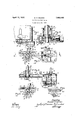
- FIG. 1 is a sectional view through a portion of a washing machine showing an -0utside elevation of my washing machine drive applied thereto. 4
- Figure 2 is an enlarged sectional viewon the line 2-2 of Figure 1 and illustrates th operating mechanism of the drive.
- Figure 3 is a vertical sectional view on the line 3'3 of Figure 2.
- Figure 4 is an enlarged vertical sectional view on the line 44 of Figure 2.
- Figure 5 is' a view similar to the left han end of Figure 2 illustrating the parts in a different position wherein the clutch member is shown in off position and F gure 6 is an enlarged sect onal view on the line 6-6 of Figure 3 illustrating the teeth of the dolly shaft pinion and rack bar in mesh in solid lines and out of mesh in,dot-' ted lines.
- My washing machine drive A consists of a housing formed of a lower portion 12 and an upper portion 14.
- the portions 12 and 14 are bolted together a by bolts or cap screws 16, a glasket being inat the housing may retain oil or grease for lubrication purposes.
- the mechanism of my improved drive consists of a drive shaft 18'journaled in a subhousing 20.
- a pulley 22 is secured to the drive shaft 18 on the outside of the "housing 20 and may be operatively connected I shearing off as when no inclin ing to the drive shaft 18 and meshes with a worm gear 28.
- the worm gear 28 is secured to a crank shaft 30 having a crank arm 32.
- a crank pin 34 is secured to the crank arm 32 and has a secondary 'crank'arm 36 secured to its upper end.
- my drive On the portion 14 of the -hous-. my drive a hub 38 is formed and adapted to receive a tubular casing 40 through which a wringer drive shaft 42 ex 10 vided in the rack bar 44 for the screw 54. 'It will be obvious that tighten
- a dolly shaft 62 J ournaled in a hub 58 formed on the housing portion 12 and in a hub 60 formed on the housing portion 14 is a dolly shaft 62.
- a dolly shaft pinion 64 is secured to the shaft 62 and has a hub 65.
- the teeth of the rack bar 44 are adapted to coact with the teeth of the pinion 64 as best shown in Figure .6.
- Such coaction is normall caused by a pivoted pressure arm 66 held in engagement with the back of the rack bar by means of a spring 68.
- the spring 68 extends into a socket nut 70 screwed into the lower portion 12 of the housing for the drive.
- a mesh between the teeth of the bar-and pinion I provide a guide washer 72 adapted to engage a guide surface '7 4 formed along the rack bar 44.
- the washer 72 is loosely journaled on the hub 65 of the pinion 64 and prevents the ends of the teeth of the rack from engaging the bottoms of the teeth on the pinion and vice versa.
- the free end of the friction arm 66 may be provided with a roller if desirable.
- a clutch member 78 having guide aces 80 and 82 adapted to coact with the hub 65 and a clutch cam shaft 84 respectively whereby the clutch member is mounted for longitudinalsliding movement.
- a cam face 86 is provided onthe cam shaft 84 with which a cross bar 88 of the clutch member 78 coact-s as shown in Figure 2-when the clutch-is in on position for allowing the drive to function.
- the clutch cam shaft 84 is given-a partial turn as shown in Figure 5 whereby the periphery thereof engages the cross bar 88 for moving the clutch member in the direction of the arrow.
- a cam surface 90 on the clutch member 78 engages the guide surface 74 of the rack bar and holds the rack bar out of engagement as shownin dotted lines in Figure 6.
- the cam surface 90 of the clutch member 78 is formed on a radius from the center of the pinion 64 when in the position shown in Figure 5 sons the rack bar when rocked during its reci ro'cating movement due to the fact that it is driven by a crank its teeth will remain the same distance from the teeth of the pinion 64.
- the guide surface 74 and guide washer 72 are provided for a similar purpose sothat the proper mesh of the teeth may .be maintained throughout the entire rocking and reciprocating movement of the rack bar-
- the clutch cam shaft,84 is suitably journaled in a hub 92 formed on the lower portion 12 of the casing for the drive and may be provided with a crank 94 for manipulating th 'ajgclutch.
- the crank 94 may be-zconnected by' alink with an operating handliei'located at any convenient point such as adjacent the periphery of the tub 10.
- a flange 95 Secured to the hub 60 is a flange 95 having a screw threaded portion 96 terminating in a sleeve 98.
- the screw threaded portion .96 is adapted to extend throughan opening in the bottom of the tub 10 andto receive a nut 100.
- a gasket is interposed between the bottom of the tub 10 and the flange 94 to seal against the leakage of water from the tublO around the sleeve 96.
- the sleeve 98 extends up into the hollow center of the dolly 76 to prevent water from flowing along the dolly shaft 62 and into the housing for the drive A.
- a dolly shaft a pinionthereon, a rack mar for co- I action therewith, mechanism for recigroca mg said rack bar, a guide device a said pinion, a guide surface on said rack bar. for coaction therewith, means to normally retain said guide device and guidesurfac'e in contact, and. a inovable'member coacting with said guide surface to separate it from. said guide device and including a cam sur'- face for coactionwith said guide surface.
- a washing machine drive - a dolly shaft, a pinion thereon, a rack bar for coaction therewith, mechanism for reciprocating said rack bar, a guide washer on said dolly shaft, a guide surface on said rack bar for coaction therewith, spring means to normally retain said washer and guide surface a in contact, and clutch means coacting with said guide surface to separate itfrom saidguide washer, 521.1(1 clutch means including a cam surface for coaotion'with said guide surface, said cam surface being on'a radius from the center of said pinion when in disengaged position.
- said clutch member having a pair of slots between which the dolly shaft and the cam are positioned, whereby to guide the clutch member in its sliding movement.
- dolly shaft a guide surface on said rack bar for coaction therewith, spring means to normally retain said washer and guide surface in contact, and clutch means coacting with said guide surface to separate it from said guide washer, said clutch means comprising a clutch member and aclutch cam, said clutch member being slidably mounted.
- said clutch means including a clutch member for coaction "with said guide surface, a clutch cam for coaction with said clutch member vto thereby move the same upon rotation of the clutch cam, said clutch member havingslots, the sides of which-coact with said dolly shaft and said clutch cam to thereby guide the clutch member.
- a dolly shaft a pinion thereon, a rack bar for coaction therewith, mechanism for reciprocating said rack bar, a guide surface on said rack bar, means to normally .retain said rack bar meshed-with said pinion and clutch means said clutch means comprising a slid-v .shaft, a ,pinion thereon, a rack bar for 00- actlon therewith, mechanism for reciprocat-.
Description
April 12, 1932. D, P, MLSON 1,853,482
WASHING MACHINE DRIVE Filed April 24, 1930 Jzwzzzlv 22/, Dona/d ajZl/z sozz We .5 5 W 152 @rzzgs Patented Apr. 12, 1932 UNITED STATES PATENT OFFICE noun. r. WILSON, or 01mm, mnasn, 'ASSIGNOR ro L. m. nncxna 00., or"
own, maasxa q WASHING- MACHINE DRIVE Application filed April M,v 1930. Serial No. 448,988.
' The object of this invention is to provide a washing machine drive that is simple, durable and comparatively inexpensive to manufacture.
i A further object is to provide a washing machine drive having novel features of construction wherein greater operating efficiency and less wearing of the parts is had and yet the device may be easily operated and thrown into and out of gear.
More particularly, it is my object to'provide a washing machine drive consistin of a motor driven crank shaft with a 'rac bar attached thereto for coaction with a pinion, the pinion being operatively connected with a washin machine dolly.
Anot er object is to provide a guide surface on the rack bar. and a guide washer or circular disk adjacent the pinion, the peri 'hery of which is concentric with the teeth 0 the pinion, whereby a spring pressure may be exerted against the back of the rack bar and yet the teeth of the bar and the pinion will not mesh too tightly.
Still a further object is to provide a clutch mechanism consisting of a clutch member adapted to engage the guide surface on the rack bar, the clutch member having a cam surface for such on agement and the cam surface being formed on a radius from the center of the pinion when the device is in disen aged position.
other object is to provide a clutch cam for actuating the clutch member and having a shaft, the clutch member bein guided by the dolly shaft or more specifica 1y a hub on the dolly shaft pinion and by the cam shaft. A further ob ect is to provide a pressure arm, spring pressed against the back side of the rack bar for holdin the teeth in mesh and actuating the clutc member to oflf position when the clutch cam is rotated to ofi position.
Still a further object is to provide a novel means of connection between a fitting on the motor driven crank shaft and the rack bar consisting of a shoulder, an inclined surface and a bolt and slot connection, whereby tightenin the bolt causes the rack bar to slide longitudinally relative to the inclined surterposed between the two so t face and engage the shoulder and' ulling strain on the rack bar tends to place t e bolt h under a stretching tension rather than a fully set forth, pointed out in my claims, and
illustrated in the accompanying drawings, in which: I Figure 1 is a sectional view through a portion of a washing machine showing an -0utside elevation of my washing machine drive applied thereto. 4
Figure 2 is an enlarged sectional viewon the line 2-2 of Figure 1 and illustrates th operating mechanism of the drive.
Figure 3 is a vertical sectional view on the line 3'3 of Figure 2.
Figure 4 is an enlarged vertical sectional view on the line 44 of Figure 2.
4 Figure 5 is' a view similar to the left han end of Figure 2 illustrating the parts in a different position wherein the clutch member is shown in off position and F gure 6 is an enlarged sect onal view on the line 6-6 of Figure 3 illustrating the teeth of the dolly shaft pinion and rack bar in mesh in solid lines and out of mesh in,dot-' ted lines.
On the accompanying drawin I have used the reference numeral 10 to mdi'cate a 1 washing machine tub. My washing machine drive A consists of a housing formed of a lower portion 12 and an upper portion 14.
The portions 12 and 14 are bolted together a by bolts or cap screws 16, a glasket being inat the housing may retain oil or grease for lubrication purposes. The mechanism of my improved drive consists of a drive shaft 18'journaled in a subhousing 20. A pulley 22 is secured to the drive shaft 18 on the outside of the "housing 20 and may be operatively connected I shearing off as when no inclin ing to the drive shaft 18 and meshes with a worm gear 28. The worm gear 28 is secured to a crank shaft 30 having a crank arm 32. A crank pin 34 is secured to the crank arm 32 and has a secondary 'crank'arm 36 secured to its upper end. On the portion 14 of the -hous-. my drive a hub 38 is formed and adapted to receive a tubular casing 40 through which a wringer drive shaft 42 ex 10 vided in the rack bar 44 for the screw 54. 'It will be obvious that tightening, the screw has;
a tendency to force the endof the rack bar against the. shoulder 48 due to the inclined surfaces 50 and 52, the slot 56 allowing for endwise movement of the bar relative to the fitting. This causes firm engagement between the shoulder 48 and the end of the rack bar 44 so-that' there is no play when a pushing movement is imparted to the rack bar by the crank shaft. When the crank shaft is pulling the rack bar the inclined surfaces tend to stretch the screw 54 so that instead of a shearing action, a stretching tension is imposed on the screw and in my, experience I have found that a screw in such aconstruction lasts practically indefinitel instead of surfaces or slot connection are provided.
J ournaled in a hub 58 formed on the housing portion 12 and in a hub 60 formed on the housing portion 14 is a dolly shaft 62. A dolly shaft pinion 64 is secured to the shaft 62 and has a hub 65. The teeth of the rack bar 44 are adapted to coact with the teeth of the pinion 64 as best shown in Figure .6. Such coaction is normall caused by a pivoted pressure arm 66 held in engagement with the back of the rack bar by means of a spring 68. The spring 68 extends into a socket nut 70 screwed into the lower portion 12 of the housing for the drive.
To preventtoo tight a mesh between the teeth of the bar-and pinion I provide a guide washer 72 adapted to engage a guide surface '7 4 formed along the rack bar 44. The washer 72 is loosely journaled on the hub 65 of the pinion 64 and prevents the ends of the teeth of the rack from engaging the bottoms of the teeth on the pinion and vice versa. Thus proper mesh is insured at all times when the drive is operating. The free end of the friction arm 66 may be provided with a roller if desirable. v
In order to disengage the rack bar 44 from the pinion 64' and thus stop the operation of the dolly shaft 62 and thedolly 76 thereon I rovide a clutch member 78 having guide aces 80 and 82 adapted to coact with the hub 65 and a clutch cam shaft 84 respectively whereby the clutch member is mounted for longitudinalsliding movement. A cam face 86 is provided onthe cam shaft 84 with which a cross bar 88 of the clutch member 78 coact-s as shown in Figure 2-when the clutch-is in on position for allowing the drive to function. 'In ,order to disengage the clutch, the clutch cam shaft 84 is given-a partial turn as shown in Figure 5 whereby the periphery thereof engages the cross bar 88 for moving the clutch member in the direction of the arrow. In this position a cam surface 90 on the clutch member 78 engages the guide surface 74 of the rack bar and holds the rack bar out of engagement as shownin dotted lines in Figure 6. The cam surface 90 of the clutch member 78 is formed on a radius from the center of the pinion 64 when in the position shown in Figure 5 sons the rack bar when rocked during its reci ro'cating movement due to the fact that it is driven by a crank its teeth will remain the same distance from the teeth of the pinion 64. The guide surface 74 and guide washer 72 are provided for a similar purpose sothat the proper mesh of the teeth may .be maintained throughout the entire rocking and reciprocating movement of the rack bar- The clutch cam shaft,84 is suitably journaled in a hub 92 formed on the lower portion 12 of the casing for the drive and may be provided with a crank 94 for manipulating th 'ajgclutch. The crank 94 may be-zconnected by' alink with an operating handliei'located at any convenient point such as adjacent the periphery of the tub 10.
Secured to the hub 60 is a flange 95 having a screw threaded portion 96 terminating in a sleeve 98. The screw threaded portion .96 is adapted to extend throughan opening in the bottom of the tub 10 andto receive a nut 100. A gasket is interposed between the bottom of the tub 10 and the flange 94 to seal against the leakage of water from the tublO around the sleeve 96. The sleeve 98 extends up into the hollow center of the dolly 76 to prevent water from flowing along the dolly shaft 62 and into the housing for the drive A.
Some changes may be made in the construction and. arrangement 'ofthe parts of my device without departing from the real spirit and purpose of my inventiomand it is my intention to cover by my claims, any modified forms of structure or use of mechanical. equivalents, which may be reasonably included within their scope.
I claim-as my invention:
1. In a washing machine drive, a dolly shaft, a pinionthereon, a rack mar for co- I action therewith, mechanism for recigroca mg said rack bar, a guide device a said pinion, a guide surface on said rack bar. for coaction therewith, means to normally retain said guide device and guidesurfac'e in contact, and. a inovable'member coacting with said guide surface to separate it from. said guide device and including a cam sur'- face for coactionwith said guide surface.
2. In a washing machine drive,- a dolly shaft, a pinion thereon, a rack bar for coaction therewith, mechanism for reciprocating said rack bar, a guide washer on said dolly shaft, a guide surface on said rack bar for coaction therewith, spring means to normally retain said washer and guide surface a in contact, and clutch means coacting with said guide surface to separate itfrom saidguide washer, 521.1(1 clutch means including a cam surface for coaotion'with said guide surface, said cam surface being on'a radius from the center of said pinion when in disengaged position.
3..In a washing machine drive, a dolly shaft, a pinion thereon, a rack bar for coaction therewith, mechanism forreciprocating said rack bar, a guide washer on said iadapted to coact with said guide surface for disengaging said rack bar from said pinion, said clutch mounted clutch'member and a clutch cam coactableltherewith to slide the same.
means comprising a shdably 7. In a washing machine drive, a dolly cam coactable therewith to slide the same,
said clutch member having a pair of slots between which the dolly shaft and the cam are positioned, whereby to guide the clutch member in its sliding movement.
Des Moines; Iowa, August 28, 1929.
-DONALD P. WILSON.
dolly shaft, a guide surface on said rack bar for coaction therewith, spring means to normally retain said washer and guide surface in contact, and clutch means coacting with said guide surface to separate it from said guide washer, said clutch means comprising a clutch member and aclutch cam, said clutch member being slidably mounted.
4. In a washing machine drive, a dolly shaft, a pinion thereon,a rack bar for coaction therewith, mechanism for reciprocating sa1 rack bar, a guide washer onsaid dolly shaft, a guide surface on said rack bar for coaction therewith, spring means to normally retain said washer and guide surface in contact, clutch means coacting with said guide surface to separate it from said guide washer, said clutch means comprising a clutch mem: ber and a clutch cam, said clutch member being 'slidably mounted and guided by said 5. In a washing machine drive, a dolly shaft, a pinion thereon, a rack bar for coaction therew1th, mechanism for reciprocating said rack bar, and clutch means to move .said
rack bar away from said pinion, said clutch means including a clutch member for coaction "with said guide surface, a clutch cam for coaction with said clutch member vto thereby move the same upon rotation of the clutch cam, said clutch member havingslots, the sides of which-coact with said dolly shaft and said clutch cam to thereby guide the clutch member. a
6. In a washing machine drive, a dolly shaft, a pinion thereon, a rack bar for coaction therewith, mechanism for reciprocating said rack bar, a guide surface on said rack bar, means to normally .retain said rack bar meshed-with said pinion and clutch means said clutch means comprising a slid-v .shaft, a ,pinion thereon, a rack bar for 00- actlon therewith, mechanism for reciprocat-.
Priority Applications (1)
| Application Number | Priority Date | Filing Date | Title |
|---|---|---|---|
| US446983A US1853482A (en) | 1930-04-24 | 1930-04-24 | Washing machine drive |
Applications Claiming Priority (1)
| Application Number | Priority Date | Filing Date | Title |
|---|---|---|---|
| US446983A US1853482A (en) | 1930-04-24 | 1930-04-24 | Washing machine drive |
Publications (1)
| Publication Number | Publication Date |
|---|---|
| US1853482A true US1853482A (en) | 1932-04-12 |
Family
ID=23774538
Family Applications (1)
| Application Number | Title | Priority Date | Filing Date |
|---|---|---|---|
| US446983A Expired - Lifetime US1853482A (en) | 1930-04-24 | 1930-04-24 | Washing machine drive |
Country Status (1)
| Country | Link |
|---|---|
| US (1) | US1853482A (en) |
Cited By (1)
| Publication number | Priority date | Publication date | Assignee | Title |
|---|---|---|---|---|
| US2672760A (en) * | 1951-04-25 | 1954-03-23 | American Bosch Corp | Windshield wiper |
-
1930
- 1930-04-24 US US446983A patent/US1853482A/en not_active Expired - Lifetime
Cited By (1)
| Publication number | Priority date | Publication date | Assignee | Title |
|---|---|---|---|---|
| US2672760A (en) * | 1951-04-25 | 1954-03-23 | American Bosch Corp | Windshield wiper |
Similar Documents
| Publication | Publication Date | Title |
|---|---|---|
| US1853482A (en) | Washing machine drive | |
| US2027659A (en) | Clutch structure | |
| US2190856A (en) | Gearshift for washing machine wringers | |
| US1077354A (en) | Alternating rotary gearing. | |
| US1695279A (en) | Washing machine | |
| US2844965A (en) | Washing machines | |
| US2494436A (en) | Combined clothes washer and extractor | |
| US1414430A (en) | Driving mechanism for washing machines | |
| US1464471A (en) | Driving mechanism for washing machines | |
| US1052010A (en) | Reversible-gear driving mechanism. | |
| US1549983A (en) | Automatically-releasable driving means for laundry machinery and the like | |
| US1354621A (en) | Driving mechanism for washing-machines | |
| US1913549A (en) | Ironer attachment for washing machines | |
| US1441643A (en) | Clutch mechanism | |
| US1445853A (en) | Automobile windshield wiper | |
| US1385806A (en) | Washing-machine mechanism | |
| US1540386A (en) | Washing machine | |
| US1516742A (en) | Clothes wringer | |
| US1855995A (en) | One belt laundry washer | |
| US1637581A (en) | Clothes wringer | |
| US2272853A (en) | Driving mechanism | |
| USRE16017E (en) | Windshield wiper | |
| US1082691A (en) | Reversing driving mechanism. | |
| US1424797A (en) | Automatic reversing mechanism | |
| US1211221A (en) | Reversing-gearing for washing-machines. |