US1853477A - Air conditioning for railway cars - Google Patents
Air conditioning for railway cars Download PDFInfo
- Publication number
- US1853477A US1853477A US508154A US50815431A US1853477A US 1853477 A US1853477 A US 1853477A US 508154 A US508154 A US 508154A US 50815431 A US50815431 A US 50815431A US 1853477 A US1853477 A US 1853477A
- Authority
- US
- United States
- Prior art keywords
- air
- car
- duct
- leading
- chamber
- Prior art date
- Legal status (The legal status is an assumption and is not a legal conclusion. Google has not performed a legal analysis and makes no representation as to the accuracy of the status listed.)
- Expired - Lifetime
Links
Images

Classifications
-
- B—PERFORMING OPERATIONS; TRANSPORTING
- B61—RAILWAYS
- B61D—BODY DETAILS OR KINDS OF RAILWAY VEHICLES
- B61D27/00—Heating, cooling, ventilating, or air-conditioning
- B61D27/0018—Air-conditioning means, i.e. combining at least two of the following ways of treating or supplying air, namely heating, cooling or ventilating
Definitions
- the system embodies a single air cir.
- culating means adapted to draw air through a refrigerating medium and discharge it into the upper portion of the car, or alternatively 15 to withdraw air from within or outside the car and discharge this air over the radiators of the heating system into the car, the air subsequently being exhausted through ven- ⁇ tilators in the upper portion of the car.
- an air duc-t or ducts are provided in the upper portion of the car with which communicate the usual ventilators leading to the outer air, the ducts also having discharge openings communicating with the space within the car. These ducts may be either utilized for exhausting spent air from the car through the ventilators, or fordischarging cooledrair into the car when the ventilators are closed.
- Thelieating system embodies concealed radiators positioned in the lower port-ion of the car, and passages are provided for either discharging air over the radiators into the caror-with'drawing air from thev lower portion ot the car when the retrigerating system is in operation'.A Valved connections are provided whereby the4 Aair circulating means can"eith'er force cooled air v ysubstantially on the .line 3f3of Fig. 1.
- the generalobject of this invention is to ⁇ lowing detailed description of certain.
- Another object is to provide an'improved Ventilating system for railway cars.
- Another Object is to provide an improved system for circulating heated air through railway cars. l r
- Another object is to provide an improved system for cooling and circulating air in railway cars.
- vAnother ⁇ object is to provide improved means for regulatingthe temperature of the air within a railway car.y
- Another object is toY provideI improved means for humidifying the air within theV railway car.
- Another object isto provide an improvedv system of air circulatingpassages Within a railway *car adapted to be used'- as part of either a heating or cooling system.
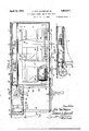
- Fig. 1 is a longitudinal section'through za.
- Fig. 2 ⁇ fis aninverted plangviewloftheiV upper, portion of the car, the .Viewbeing takensubstantially on the line 2V-f2 of'Fi .1.
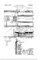
- Fig.V 3 isaV transverse vertical 'scctionita en
- Fig. 4 isa transverse Vertical section taken 1.
- the body portion of the car is indicated more or less diagrammatically, the at 1, the side walls at 2, the windows at 3, the roof at 4, and the clear story at 5.
- a fragment of the underframe is indicated at 6 but the trucks and gearvare not shown.
- a vapor or steamY heatingsystem of the type partially disclosed vherein will be incorporated in this combined system.
- the heating unit herein shown will be'fpos'itioned at one side of the car for all or a portion of the length thereof depending upon the' type of car to which the system is adapted.
- a simi- "lar heating unit is used at the opposite side ofthe car,"a ⁇ ndV in cars having passenger spaces 'ofv considerable length, such i as coaches
- two suahheatingsystems may be used yat one side of the car one leading from each end of the car to a .position substantially midway of thecar. I't will be' understood that these same remarks apply to manyfeatures of the cooling and ventilatingsystems hereinafter disclosed.
- vapor regulator 7 is connected with the distributing valve 10 ybythe supply and return pipes 8 and' 3 respectively.
- a manually operated controller l1 is indicated forthe distributing valve, but it is Vto VVbe understood that this valve may be controlled thermostatically in response 4to temperature changes Within the car,"in the'manner wellV knownV in this" art.
- a radiating pipe loop consistingof theup'per inletpipe turn Vpipe ⁇ l ⁇ 4Y receives vapor fromrand'dis# 1 2, loop 13 andllower rechargesgases andcondensate back into the distributing?
- valve 10. This radiating loop -is vfr oiilf1-ted within theilower side wallof .the-A railway'T car,V and Yin ⁇ each space' 15 'beneath oneof the windows 3 ⁇ isprov ⁇ ided withV a plun 1 6 ⁇ to provideextended these points;v Each radiatiiig" surfaees 5 at heating space 151is'provided with@ lower.
- each of these closures consists of a plurality of vanes or louvres 2T which may be simultaneously swung together to close the opening or swung out at angles to permit a freepassage of air through the opening.
- the duct 24 is of generally triangular cross section with a concaved inner side so as to conform to the general outlines of the car roof. As shown in Figs. 1, 2 and 3, this duct communicates with the space within ⁇ the car along its lowerV edge through a plurality of. openings V28 above and at either side of abottom closureor bafHe member 29. In the modied formshown in Fig. 4, the outlets 28 and baffle 29 are positoned to communie c cate with an outlet 30 at the upper inner edge ofthe triangular duct 24.
- This particular form of air duct is preferable for use in Pullman cars or sleepingcars where it is preferable t'o discharge the cold air nearer the center of the car and not directl f above the upper berths at either side of t e car. Except for the position of these air outlets or inlets, the formsof airducts 24 are the same in both FigsB and 4. f
- AThe humidifier 23 already referred to, a refrigeratingelement 31, and a suitable fan or other air circulating means 32, are'all located in a chamber ,33 which may be located in any'available position in the car, but is desirably located overhead and adjacent the end ofthe car as indicated inthe drawings.
- Chamber 33 has a suitable air'V inlet 34 communicatingwith'the outer air and provided a closure adjustable by anysuitable means such as 35v so as to cutoff or regulate the'inlowof outside air tof'ch'amber 33.
- the humidifier 23 may beof any'approved type, preferably comprising a plurality of pans or receptacles containing water'and a suitable lheating element iforexpediting the vaporiza-
- the refrigeratingV elei ment-31 may be of any Aapproved type, either ice.'v It will begof c mechanical or cooled seine open construction so that air may flow through in contact witlnthe refrigerating-- elements.
- the fan 32l hasfaninlet 36 forV withdrawing air froinchamber 33, and a disv charge passage 37 which communicates at 38 with the inlettoairduct24.
- IA second air passage 39 leads at 4 0 fronti-the Idischarge port 37 of the fan, 'this passage 39 leading down at one side of the ear and communicatmg with a. horizontal passage 41 which rill 43 through which air may be discharged l rom passage 41 into the space v15 containing the radiatinor unit, or, conversely, air may be Withdrawn Irom this space 15 into passage 41 when the refrigerating system is in operation.
- the lower air passage 4l will decrease in area as it progresses length- Wise of the car from the vertical passage 39L so as to provide amore equal-distribution of air through the several outlets 42.
- a closure member or valve 44 pivoted at 45 may be swung from a horizontal position closing the air passage 39 from the discharge port 37 of the fan, as shown in solid lines in Fig. 5, to a vertical position as shown in dotted linesin Fig. 5, in which latter position it will cut off the air duct 24 from the discharge port of the fan.
- An outlet provided with a valve or closure 46 is provided in the upperv portion of air passage 39 adjacent the air inlets to chamber 33 hereinafter described.
- a manually operable lever 47 is connected by means comprising a slide rod 48 with theseveral closures 27 for ventilators 25, and this same operating mechanism hasrod and lever connections indicated generally at .49 with the two valves or closures 44 and 46.
- a heating system inc uding a plurality of radiators in the lower portion ofthe car, an air duct in the ⁇ upperv portion of the car provided with' a v plurality of outlets leading to the space within the car, a plurality of ventilators connecting the duct with the outer air, a refrigerating means and an air circulating means and mov,
- an air duct extending through the upper portion of the car and provided with a plurality of spaced outlets leading into the space within the car, a refrigerating element, an air ⁇ ci rculating blower, two air inlets to the blower, one leading directly from the space within the car, and the other leading through the refrigerating element, and means for alternatively opening and closing these inlets.
Description
April l2, '1932. J. VAN VULPEN l-:T AL 1,853547 7 I AIR CONDITIONING FOR RAILWAY CARS Filed Jan. l2, 1951 3 Sheets-Sheet l ,miel
- @mais Apnl l2, 1932. J. VAN vULPl-:N ET AL 1,853,477
AIR CONDITIONING FOR RAILWAY CARS Filed Jan. 12, 1931 3 Sheecs-SheelI `2 u fo n lz n April 12, `193`2- J. VAN vULPl-:N ET AL 1,853,477
AIR CONDITIONING FOR RAILWAY CARS Filed Jan. 12, 1931 3 Sheets-Sheet 3 ORS Imfe` I z (MJIMe/z Y andEdz//aIa/ ZAS'J@ www y fm Patented Apr. 12, 1932 UNITED STATES PATENTl OFFICE JOHN VAN VULPEN AND EDWARD A. RUSSELL', OF CHICAGO,ILLINOIS, ASSIGNORS TO VAPOR CAR HEATING COMPANY, INC., OF CHICAGO, ILLINOIS, A CORPORATION OF NEW YORK AIR CONDITIONING FOR RAILWAY` CARS Application led January 12, 1'9'31. Serial No. 508,154.
10 perature conditions may require. Brieiiy described, the system embodies a single air cir.
culating means adapted to draw air through a refrigerating medium and discharge it into the upper portion of the car, or alternatively 15 to withdraw air from within or outside the car and discharge this air over the radiators of the heating system into the car, the air subsequently being exhausted through ven-` tilators in the upper portion of the car. More speciiically, an air duc-t or ducts are provided in the upper portion of the car with which communicate the usual ventilators leading to the outer air, the ducts also having discharge openings communicating with the space within the car. These ducts may be either utilized for exhausting spent air from the car through the ventilators, or fordischarging cooledrair into the car when the ventilators are closed. Thelieating system embodies concealed radiators positioned in the lower port-ion of the car, and passages are provided for either discharging air over the radiators into the caror-with'drawing air from thev lower portion ot the car when the retrigerating system is in operation'.A Valved connections are provided whereby the4 Aair circulating means can"eith'er force cooled air v ysubstantially on the .line 3f3of Fig. 1.
from the refrigerating ,system `through the duc-ts into the car, Yor vorceair through the lower passages over the radiators when the heatingsystem is in operation.v An aiiilcty is provided for drawing inlair from'outside y the car, and means provided for humiditying this .,air.- Thermostatically controlled inlets to the air circulatinggmeans control-the air circulation .so that when 'the temperaturev within thel car hasbeen sufficiently lowered, the air will be inerolvcirculate'd without passing through the reirigeratingmeans.
The generalobject of this invention is to `lowing detailed description of certain.
:substantially on the line v4---4 of Fig..
provide a combined temperature controlling and Ventilating system of the type briefly described hereinabove and disclosed more in 'detail in the specifications which follow.
Another object is to provide an'improved Ventilating system for railway cars. Another Objectis to provide an improved system for circulating heated air through railway cars. l r
Another object is to provide an improved system for cooling and circulating air in railway cars.
vAnother `object is to provide improved means for regulatingthe temperature of the air within a railway car.y
Another object is toY provideI improved means for humidifying the air within theV railway car.
Another object isto provide an improvedv system of air circulatingpassages Within a railway *car adapted to be used'- as part of either a heating or cooling system.
Other objects and'advantages of this in- Ventionwill be more apparent from `the folprinciples of this invention;
a tge.
' In the accompanying drawingsz.
Fig. 1 is a longitudinal section'through za.
proved `forms `of apparatus `embodying "portion, of va railway car, partially broken away, Vmany of the features of this temperaturecontrolling and Ventilating system being.k indicated diagrammatically.A
Fig. 2` fis aninverted plangviewloftheiV upper, portion of the car, the .Viewbeing takensubstantially on the line 2V-f2 of'Fi .1.
Fig.V 3 isaV transverse vertical 'scctionita en Fig. 4 isa transverse Vertical section taken 1. In Figrlt a lmodified formiof,ventilatinl duct is shown in the top ofthe car, otherwise'the v disclosure is the same as inFigsl 1- and2` Fig;v 5 `is' apartial Vertical section taken` YIigng is a'p'artial longitudinalsectizon" 1showingaA modified form of heating system.V SFig.Y 7 'is a" partial vertical section, on a yeo i oor being shown with heat-insulated walls. As shown in the drawings, the body portion of the car is indicated more or less diagrammatically, the at 1, the side walls at 2, the windows at 3, the roof at 4, and the clear story at 5. A fragment of the underframe is indicated at 6 but the trucks and gearvare not shown.
Various types of heating systems may be used, but preferably a vapor or steamY heatingsystem of the type partially disclosed vherein will be incorporated in this combined system. The heating unit herein shownwill be'fpos'itioned at one side of the car for all or a portion of the length thereof depending upon the' type of car to which the system is adapted. It willbe understood that a simi- "lar heating unit is used at the opposite side ofthe car,"a`ndV in cars having passenger spaces 'ofv considerable length, such i as coaches, two suahheatingsystems may be used yat one side of the car one leading from each end of the car to a .position substantially midway of thecar. I't will be' understood that these same remarks apply to manyfeatures of the cooling and ventilatingsystems hereinafter disclosed.
` Referring first to the type of heating system` shown in vFigspl to 5. inclusive, the vapor regulator -7 positioned beneath the car 1s connected with the source of steam supply.
in theusual manner-,fand is adapted to discharge condensate and non-eondensable gases beneath the -c'arin' the usual manner. The vapor regulator 7 is connected with the distributing valve 10 ybythe supply and return pipes 8 and' 3 respectively. "A manually operated controller l1 is indicated forthe distributing valve, but it is Vto VVbe understood that this valve may be controlled thermostatically in response 4to temperature changes Within the car,"in the'manner wellV knownV in this" art. A radiating pipe loop consistingof theup'per inletpipe turn Vpipe`l`4Y receives vapor fromrand'dis# 1 2, loop 13 andllower rechargesgases andcondensate back into the distributing? valve 10.` This radiating loop -is vfr oiilf1-ted within theilower side wallof .the-A railway'T car,V and Yin `each space' 15 'beneath oneof the windows 3`isprov`ided withV a plun 1 6^ to provideextended these points;v Each radiatiiig" surfaees 5 at heating space 151is'provided with@ lower. air inlet 17 adjacent the-Hoor 1', Vand upper Vair.outlets 1'8fandi19fthe outlet 18 discharg-g ing `heated air voutwardly'into the of the ear, and theoutltf 1 9 discharging heated `air upwardly V through lthe window 1120.
The floi'v' Ofair into a' ndfithrough the lifeatingspacel'ris indicated-by the'sniall arrowsV in Fig". 4., TA' secendfheatingllcob amplia ing pipes 21and 22 isv shown'as eatendingA running with ltion of. the water@ that communication between the air ducts L and the ventilators may be cut oif When de!) sired. In the form here shown, each of these closures consists of a plurality of vanes or louvres 2T which may be simultaneously swung together to close the opening or swung out at angles to permit a freepassage of air through the opening. In the forni here` shown, the duct 24 is of generally triangular cross section with a concaved inner side so as to conform to the general outlines of the car roof. As shown in Figs. 1, 2 and 3, this duct communicates with the space within `the car along its lowerV edge through a plurality of. openings V28 above and at either side of abottom closureor bafHe member 29. In the modied formshown in Fig. 4, the outlets 28 and baffle 29 are positoned to communie c cate with an outlet 30 at the upper inner edge ofthe triangular duct 24. This particular form of air duct is preferable for use in Pullman cars or sleepingcars where it is preferable t'o discharge the cold air nearer the center of the car and not directl f above the upper berths at either side of t e car. Except for the position of these air outlets or inlets, the formsof airducts 24 are the same in both FigsB and 4. f
A closure member or valve 44 pivoted at 45 may be swung from a horizontal position closing the air passage 39 from the discharge port 37 of the fan, as shown in solid lines in Fig. 5, to a vertical position as shown in dotted linesin Fig. 5, in which latter position it will cut off the air duct 24 from the discharge port of the fan. An outlet provided with a valve or closure 46 is provided in the upperv portion of air passage 39 adjacent the air inlets to chamber 33 hereinafter described. A manually operable lever 47 is connected by means comprising a slide rod 48 with theseveral closures 27 for ventilators 25, and this same operating mechanism hasrod and lever connections indicated generally at .49 with the two valves or closures 44 and 46. When the lever 47 is swung to one positiolnfor ex# ample as shown in. thedrawngs, the `closures 27 for the ventilators will all be moved -to closed position, valve or closure 44 Willfbe moved to cut oil'l the air passagev39 and open the air duct 24 to the dischargeof fan 32. and valve or closure 46 in air passage 39 will be opened. When the lever 47 is swung tothe other position, closure 46 will bel closed', clo-1 from the space Within the car to the chamber f 33. These inlets are providedv with closures 52 and 53 respectively, in the form here shown consisting of'vanes or louvres which may be4 shiftedfrom the closed position shown at v52 to the open position shown at 53. An' operating motor 54 is .connected'gwith these `closures lthrough links `55 so that" whenV onel closure such as 52 is shifted to closed -position'the other closure'such as'53'will bemoved to open position, and vice versa. I hen.V closure;-` 53 is open as shown in`thedrawings) ,the {ar delivered through-this inletfromth'e interior; of the car passessdirectly.'toitheinlet 360i.- fan 32. Then closure 53 isv closed andfclosure;
52 is open, the air` passing through inlet 50 must pass'through refrigerating element 31 before it reaches the inlet to fan 32. The motor 54 is controlled from a thermostat 56 positioned within the passenger compartmentof the car. This samethermostat could be used to control the distributing valve of the heatingsystem.
In the general operation of this system,
supposing that temperature conditions/are such that it is desirable to .supply heat to the car, the control lever 47 will be shifted so Athat the ventilators 25 vwill be opened,the
closure 44will be moved to vertical osition tocut off the air duct 24 from the an and open the air passage 39 sol that the fan will discharge its air through this air passage. The closure 46 in passage 39-Will`be moved to closed position, and the air inlet 51 willautomatically be moved ,to the open position shown in the drawings on account of the low temperature existing in the car. The fun 32 will now withdraw air from within the cary through inlet 51, and additional outside air maybe drawn in through inlet34, the desired moisture being added by means ofthe humidifier 23. This air is forced through air passages 39 and .41 and'discharged through the outlets 42 into the spaces 15 wherein it is heated by passage over the radiatin units and discharged into the interioroi tie car through outlets 18 and 19. Thespent air isV so. as to close the ventilators 25 and open the airfduct 24 to thecdischargeport 37 of fan 32. Y
At this time the air passage 39 will be out off from the fan by closure 44 and the airport 46 in air passage 39 will be opened, as noW-indicated in Fig. 1'. Assuming that the temperature in thepassenger compartment of the car isabove the desired temperature fork which thermostat56 is adjusted, the motor 54 will have operated to open'the valveor closure 52 and close vthe valveor closure 53.- Air willbe drawn. into chamber 33 through 'opening 50 (and from theoutside airY through inlet 34 if desired) andthisair will be drawn through the refrigerating element 31 and cooled and then discharged through air duct 2,4 and outlets 28 into the interior of the car.- rIt will be noted that the ventilators 2,5 are now closed so that the coldairforced into theduct or ducts-,24 will be discharged yinto the car instead Yot'- to the outer air. 'Air' from within the car isdrawninto chamber 3,3 throughl in. let passage 50, and arwill also be sucked.
ifi-om the lowervpportionof the car through gril1es;43,passages42, airy-passages 41 'and` 39-.and outlet 46 and thence through inlet a5 0 into chamber` 33. In this manner a down, ward; circulation of the. cooledvairuvillfbe VmaintainedA throughout the. cai--QWhen thei130 temperature has been lowered to the desired point, thermostat 56 will cause motor 54 to close the opening 50 and open the inlet 5l so that the air drawn from within the car into chamber 33 will passdirect to the inlet 36 of the fan and not through the refrigerating ele-I ments 31. In this manner the air ciiculatioii within the car will be kept up, but the temperature of this air will no longer be lowered through contact with refrigerating element 31'; TVhen the temperature has againrisen above the desired point, tlieiniostat 56 will again actuate motor 5a to cause the closures 52 and'53 to be shifted so that the air cui'rent will again pass through refrigerating element 3l. v
As indicated in Fig. 2, a single chamber 33 is positioned in the upper portion of the car midway between the sides, and a pair ot fans 32 situated in this chamber areadapted to Ypropel air through the respective sets of ducts-orair passages at each side of the car.
VAlternetively, a separate chamber 33 and a coiri'ilcte set of the elements shown therein in Fig. l, could be positioned at each side-of the car so as to serve Vthe distributing y ducts or passages at that side of the car.
In Figs. 6 and 7 is indicated a modified" forrn of heating' system adapted for installation in old cars in which it would be impracticable toloc'ate the radiators directly in the side walls ofj the car. A separate heating chamber extending longitudinally ofthe car is built into the lower side corner thereof, such chamber comprising a front -wall 57, a coverV plate or sill 58 and an'insulated back wall and reiiecting plate 59. In this case the` radiating iins V16 may be positioned along the entire lengthof the pipes l2 andli of the radiating loop so as to form a continuous radiator throughout the length of the heating chamber. A. plurality of air inlets 60 and air outlets 61V are positioned in the front wall 57 I yofthe heating chamber, respectively below -i forni of'theinvention is much the same-asde-g; Y scribed i'nconnection with Figs. ltor inclusive. -I Y Itfisto befunderstoodthat theenclosedfanV 32 fis 'intended to Arepresent.any suitable form and'above the radiating pipes.' In the lower portion of the heating chamber is positioned an air passage 62 which corresponds to the air- Y passage' 4l of the first desciibed form orf-thev invention; This passage' 62 is provide'dwith i lating system for railway cars, a heatingsysas it progresses longitudinally of thefcar thereby providing for a more equal distribution 'of air throughout the length of the passage.. 'The inlet end of air passage 62 iscon= ne'ctedwith 'oiie`\0f the vertically extending V`ai'i" `{p'assages 39, 'andflthe' operation Vof this `within the car openin gates, can be used to` control the air flow through the various passages and the general teim Valves as herein used is intended to cover all such alternative forms of closures.
IVe claim: Y
l. In a temperature controlling and ventilating system for railway cars, a heating system including radiators in the lower portion of theczli-l'li air duct in the upper portion of the carfventilators connecting said duct with the outer air, there being a plurality of outlets from said duct to the space within the carfaV refrigerating means, an air circulating means, andvalved passages whereby air may be circulated by said circulating means either ,through the refrigerating means and said duct and forced into theupper portion of the car, or circulated in contact with the radiators and exhausted through the duct and the ventilators. g i
' 2. Ina temperature controlling and ventilating system for railway cars, aheating system including radiators in the lower portion of the caigan air duct in the upper portion of the car, ventilators connecting said duct with the outer air, there being a pluralit of outlets from said duct to thespace within the car, an air passa-ge leading to the lower portion ofthe car andhaving outlets to the space vwithin the car opening beneath the radiators,
a'chamber having valved connections to the duct and passage, a refrigerating means and an air circulating means positioned in the -chambeig and a valved air Yinlet to the chamclosed,`for-may be circulated through the airY passage and in contact with the radiators and exhaustedV through the duct and ventilators.
3. In a temperature controlling andventitem including radiators in' the lower portion of the car, an airr duct in the upper portion of l I y the car, ventilatorsconnecting said `duct with Vtei-vals as indicated at 64 to decrease this areaYY the outerair', there being a plurality of outlets from said duct tothe space Within the car, anair passage leading to the lower portion-of the carand having outlets to the space o' beneath fthe radiators, a chamber havingivaIX-*ed connections tothe duct`v and passage;fa.; refrigerating means and Vvan air circulating means positioned in the chamber, and .avalved'air' inlet Vleading to the chamber Y m -thef'spac'e' "within the cai, a valved air inletto thch'amber from the outer air,`said valved passages nndwentilators being adjustable so that air may be circulated from the car through the refrigerating means and duct and discharged into the upper portion of the car with they ventilators closed, or may be drawn from the outer air, forced through the passage in Contact with the radiators and exhausted through the duct and ventilators.
l 4. In a temperature controllinof and venti-` lating system for railway cars, a heating system including radiators in the lower portion of the car, an air duct in the upper portion of the car, ventilators connecting said duct with the outer air, there being a plurality of outlets from said duct to the space within the car, an air passage leading to the lower portion of the car and having outlets to the space within the car opening beneath the radiators, a chamber having valved connections to the duct and passage, a refrigerating means and an air circulating means positioned in the chamber, and a valved air inlet leading to the chamber from the space within the car, a valved air inlet to the chamber from the outer air, a humidifier in the chamber between the latter inlet and the air circulating means, said valved passages being adjustable so that air may be circulated from the car through the refrigerating means and duct and discharged 3D into the upper portion of the car, with the ventilators closed, or may be drawn from the outer air through the humidifier and forced through the passage over the radiators and exhausted through the duct and ventilators. 5. In a temperature controlling and Ventilating system for railway cars, a heating system including a plurality of radiators' in the lower portion of the car, an air duct in the upper portion of the car provlded with a plurality of outlets leading to the space within theA car, a plurality of ventilators connecting the duct with the outer air, a refrigeratlng Ineans and an air circulating means and a chamber in which said means are located, said air duct leading from said chamber, an an' passage leading from the chamber to the lowt er portion of the car and having'outlets to the interior of the car beneath the several radiators, a closure for the opening between the chamber and air duct, a closure for the opening from the chamber to the ai 1` passage, means for opening the closure leadlng to the duct, closing the closure leading to the passage and closing the ventilators, or alternatively closing the ventilators, opening the closure leading to the duct and closing the closure leading to the passage, an air mlet to the chamber through which air withdrawn from within the car will pass through the refrigerating means, and a thermostatically 0p'- erated closure for this inlet;
6. In a temperature controllingy and Ventilating system for railway cars,a heating system including a plurality of radiators in the lower portion of the car, an air duct in the upper portion ofthe car provided with a. plurality of outlets leading to the space within thecar, a plurality of ventilators connecting the duct with the outer air, a refrigerating means and air circulating means'and a 7.0` chamber in which said means are located,said air duct leading from said chamber, an air passage leading from lthe chamber to the lower portion of the car and having outlets to the interior of the car beneaththexseveral 'radiators, a closure for the opening between the chamber and air duct, a closure'for the opening from the 'chamber' to the air passage, means for opening the closure'leading "tof the duct, closing the closure leading to :the pa's-`v- 8P; sage and closing the ventilators, or alterna-3 tively closing the ventilators, opening the clot-f. sure leading to the duct and closing'the :closure leading to the passage, air'inlets tothe chamber from the space within the car, one inlet leading directly to the air circulating means and the other leading through the refrigerating means, closures for these inlets, and thermostatic means for n alternatively opening and closing these inlets in accordance with temperature conditions within theV car. 7. In a temperature Vcontrolling and Ventilating system for railway cars,-a heatl ing system including a plurality ofradiatorsv inthe lower portion of the car, an air 4duct in the upper portion of thecar'provided with a plurality of outlets leading to the space within the car, a plurality of ventilators connect- .ing the duct with the outer air, a refrigerating means and air circulating means and a vchamber in which said means are located, said air duct leading fromsaid chamber`,"a'n air passage leading from the chamber to the lower portion of the car and having outlets to the interior of the car beneath the several radiators, a closure for the opening between the chamber and air duct, a closure for the opening from the chamber to the air assage, means for opening the closure lea ing to the duct, closing the closure leading to the n passage and closing the ventilators, or alternatively closing the ventilators, opening the closure leading to the duct and closing'the closure leading to the passage, air inlets to the chamber from the space withinthe car, one inlet leading directly to the air circulating means and the other leading through therefrigeratingmeans, closures for these inlets, a motor for closing one inlet and simultaneously opening the other or vice versa, and thermosatic means for controlling the motor.
8. In a temperature controlling and ventilating s stem for railway cars, a heating system inc uding a plurality of radiators in the lower portion ofthe car, an air duct in the` upperv portion of the car provided with' a v plurality of outlets leading to the space within the car, a plurality of ventilators connecting the duct with the outer air, a refrigerating means and an air circulating means and mov,
air passage leading from the chamber to the lower portion of the car and having outlets to the interior of the car beneath theseveral' radiators, a closure for the opening between the chamber and air duct, a closure for the openin from the chamber to the air passage, means or opening the closure leading to the duct, closing the closure leading to the passage and closing the ventilators, or alternatively closing the ventilators, opening the closure leading to the duct and closing the closure leading to the passage, an air inlet to the chamber through which air withdrawn from within the car will pass through the refrigerating means, a thermostatically operated closure for this inlet, a valved inlet to the chamber from the outside air and a humidifier in the chamber between this inlet and thel air circulating means.
9. In a temperature controlling and venti- Vlating system for railway cars, a heating system including a lurality of radiators in the Ilower'portion o the car, an air duct in the upper portion of the car provided with a plurality of outlets leading to the space within the car, a plurality of ventilators connecting theduct with the outer air, a refrigerating means and an air circulating means and a chamber vin which said means are located, said air duct leading from said chamber, an
'air-passage leading from the chamber to the lower portionof the car and having outlets to the interior of the car` beneath the several radiators, a closure for the opening between the chamber and air duct, a closure for the opening from the chamber to the air passage,
Y means for opening the closure leading to the duct, closing the closure leadingto the passage and closing the ventilators, or alternatively closing the ventilators, opening the closure leading to the duct and closing the closure leading'to the passage, an air inlet to the chamber through which air withdrawn from within the car will pass through the refrigerating means, a valved outlet from the air passage opening adjacent the air inlet, said valved outlet being opened when the ppening to the passage from the air circulatf' lng means is closed, and a thermostatically operated closure chamber. y
10. In a Ventilating system for railway cars, a duct extending along the upper portion of the car, ventilators between said duct and the outer air, said duct having a plurality vfor the air inlet to the of air outlets leading to the space within the car, a second duct having outlets communieating wlth the lower portion of the space within the car, an air circulating blower,-
outlets leading from the blower to each of the ducts, valve means for opening and closing each vblower outlet and for opening and closing the ventilators, and connections whereb the ventilators will be closed when the out et from the blower to the upper duct isopen at which time the blower outlet to the lower duct will be closed, and when the blower connection to the upper duct is closed and the connection to the lower duct is opened, the ventilators will be opened.
11. In a Ventilating system for railway cars,a duct extending along the upper portion of the car, ventilators between said duct and the outer air, said duct having a plurality of air outlets leading to the space within the car, a second duct havingoutlets communicating with the lower portion of the space within the car, an air circulating blower, outlets leading from the blower to each of the ducts, valve means for opening and closing each blower outlet and for opening and closing the ventilators, and connections whereby the ventilators will be closed when the outlet from the blower to the upper duct is open at which time the blower outlet to the lower duct will be closed, and when the blower connection to the upper duct is closed and the connection to the lower duct is opened, the ventilators will be opened, and valved inlet passages to the blower whereby air may be withdrawn either from the space within the car or from the outer air.
12. In a Ventilating system for railway cars, a duct extending along the upper portion ofthe car, ventilators between said duct and the outer air, said duct having a plurality of air outlets leading to the space within the car, a second duct having outlets communicating with the lower portion of the space withm the car, an air circulating blower, a chamber in which vthe blower is posi-v tioned, air inletsv leading to said chamber from the outer air and from the space within the car respectively, means for separatel controlling said inlets so that either or bot may be opened, outlets leading from the blower to each of the ducts, valve means for opening and closing each blower outlet and for opening and closing the ventilators, and connections whereby the ventilators will be closed when the outlet from the blower to the upper duct is open at which time the blower outlet to the lower duct will be closed, and when the blower connection to the upper duct is closed and the connection to the lower duct is opened, the ventilators will be opened, and valved inlet passages to the blower whereby air may be withdrawn either from the space within the car or from the outer air.
13. In a Ventilating system for railway cars, a duct extending along the upper portion of the car, ventilators between said duct and the outer air, said duct having a plurality of air outlets leading to the space within the car, a second duct having outlets com municating with the power portion of the space within the car, an air circulating blower, a chamber inwhich the blower is posilll tioned, a humidifier in said chamber, air inlets leading to said chamber from the outer air and Yfrom the space within the car respectively, means for separately controlling said inlets so that either or both may be opened,
outlets leadingfrom the blower to cach ofV opened, the ventilators will be opened, and.
valved inlet passages to the blower whereby air may be withdrawn either from the space within the car or from the outer air. Y
14:. In a heating and Ventilating means for railway cars, a heatingv system comprising radiators mounted in the lower side portions of the car, au air duct having openings beneath the radiators, an air-circulating blower, and alternative connections` between the blower and duct whereby air may either be forced through the duct and over the radiators or drawn through the duct from the lower `portion of the enclosed space within the car.
15. In a heating and Ventilating means for railway cars, a heating system comprising radiators mounted in the lower side portions of the car, an air duct having openings be neath the radiators, an air-circulating blower, a passage through which air may be forced from said blower into the upper portion of the space within the car, and valve means for alternatively opening said duct to either the inlet or outlet of the blower and for opening or closing the passage leading from the blower, whereby air may be forced through the duct and over the radiators, or may be drawn from the lower portion of the car and projected through the passage into the upper portion of the car.
16. In a cooling and ventilatin system for railway cars, an air duct extending through the upper portion of the car and provided with a plurality of spaced outlets leading into the space within the car, a refrigerating element, an air`ci rculating blower, two air inlets to the blower, one leading directly from the space within the car, and the other leading through the refrigerating element, and means for alternatively opening and closing these inlets.
17. In a cooling and Ventilating system for railway cars, an air duct extending through the upper portion of the car and provided with a plurality of spaced outlets leading into the space within the car, a refrigerating element, an air circulating blower, two air inlets to the blower, one leading directly from the space within the car, and the other leading through the refrigerating element, and thermostatically controlled means for alternately opening one inlet and closing the other in accordance with temperature conditions existing within the car..
18, In a cooling and Ventilating system for railway cars, an airduct extending through the upper portion of the car and provided with a plurality of spaced outlets leading into the space ywithin the car, a refrigerating element, an air circulating blower, a chamber in whichthe refrigerating element is positioned having an outlet leading through the blower and an inlet leading from the space within the car, a second air inletflead-y ing directly from the space within the car to the blower, closures for the two inlets, a
motor for alternatively opening one closure and slmultaneously closing the other, and a thermostat positioned within the car for con- ,t'rollin the motor.
19,.` n a temperature controlling and ventilating system for railway cars a heating system including radiators positioned -in the lower. portion of the car, an air duct in the upper portion of the car, there being a plurality of outlets from the duct to the space within the car, a refrigerating means, an air circulating means, and valved passages through which air may be forced by said circulating means either to the refrigerating means and said duct into the upper portion of the car, or discharged into the lower portion of the car after passing in contact with the radiators.
JOHN VAN VULPEN. EDWARD A. RUSSELL.
DISCLAIMER `1,853,477.J0h' Van -Vulpen and Edward A. Russell, Chicago, Ill. AIR CONDI- TIONING F'ORRAILWAY Cans. Patent dated April 12, 1932. Disclaimer e filed August 8, 1934, by the assignee, Vapor Car Heating Company, Inc. Hereby enters this disclaimer to claims 16, 17 and 18 of vsaid patent, which are in the followin words, to-wit: Y
16. Ina coo ng and Ventilating system forA railway cars, an air duct extending through the upper portion of the car and provided with a plurality of spaced outlets leading into the space Within the'car, a refrigerating element, an air circulating blower, two air inlets to the blower, one leading directly from the space withinthe car, andthe other leading through the refrigerating element, and means for alternatively opening and closlng these inlets. v
' 17. In a coollng and Ventilating system for railway cars, an air duct extending through the upper portion of the car and provided with a plurality of spaced outlets leading into the space within the car, a refrigerating element, an air circulating blower, two air inlets to the blower, one leading directly from-the s ace within the car, and the other leading through th'e refrigerating element, and t ermostatically controlled'm'eans for alternately opening one inlet and closing the other in accor ance with temperature conditions existing'within the car.
f18. In a cooling and Ventilating-'system for railway cars, an air duct extending through the'upper portion of the car and provided with a plurality of spaced outlets leading into the space within the car, a refrigerating element, an air circulating blower, a chamber in whichv the refrigerating element is positioned having an outlet leadin through the blower and an inlet leading from the space within the car, a secon air inlet leading directly from the space within the car to the blower, closures vfor the two inlets, a motor for alternatively openin vone Vclosure and simultaneously closingthe other, and a thermostatf'positioned wlthinthe car for controlling the motor.
. I. [Oficial Gazette September-4, 193451,'
Priority Applications (1)
| Application Number | Priority Date | Filing Date | Title |
|---|---|---|---|
| US508154A US1853477A (en) | 1931-01-12 | 1931-01-12 | Air conditioning for railway cars |
Applications Claiming Priority (1)
| Application Number | Priority Date | Filing Date | Title |
|---|---|---|---|
| US508154A US1853477A (en) | 1931-01-12 | 1931-01-12 | Air conditioning for railway cars |
Publications (1)
| Publication Number | Publication Date |
|---|---|
| US1853477A true US1853477A (en) | 1932-04-12 |
Family
ID=24021607
Family Applications (1)
| Application Number | Title | Priority Date | Filing Date |
|---|---|---|---|
| US508154A Expired - Lifetime US1853477A (en) | 1931-01-12 | 1931-01-12 | Air conditioning for railway cars |
Country Status (1)
| Country | Link |
|---|---|
| US (1) | US1853477A (en) |
Cited By (7)
| Publication number | Priority date | Publication date | Assignee | Title |
|---|---|---|---|---|
| US2848199A (en) * | 1955-11-28 | 1958-08-19 | Crane Co | Baseboard convectors |
| US2935307A (en) * | 1954-02-24 | 1960-05-03 | Robertson Co H H | Air conditioning and distributing structure |
| US3008694A (en) * | 1951-06-29 | 1961-11-14 | Gen Motors Corp | Coach heating, cooling and ventilating system |
| US3426177A (en) * | 1966-08-24 | 1969-02-04 | Budd Co | Heater duct arrangement |
| EP0433567A2 (en) * | 1989-12-18 | 1991-06-26 | Mercedes-Benz Ag | Convector for internal heating of a large-volume vehicle |
| US20090098816A1 (en) * | 2007-10-16 | 2009-04-16 | Mccii Holdings Ab | Air-handling device |
| US20130233510A1 (en) * | 2012-03-09 | 2013-09-12 | Ics Group Inc. | Liquid heating system |
-
1931
- 1931-01-12 US US508154A patent/US1853477A/en not_active Expired - Lifetime
Cited By (8)
| Publication number | Priority date | Publication date | Assignee | Title |
|---|---|---|---|---|
| US3008694A (en) * | 1951-06-29 | 1961-11-14 | Gen Motors Corp | Coach heating, cooling and ventilating system |
| US2935307A (en) * | 1954-02-24 | 1960-05-03 | Robertson Co H H | Air conditioning and distributing structure |
| US2848199A (en) * | 1955-11-28 | 1958-08-19 | Crane Co | Baseboard convectors |
| US3426177A (en) * | 1966-08-24 | 1969-02-04 | Budd Co | Heater duct arrangement |
| EP0433567A2 (en) * | 1989-12-18 | 1991-06-26 | Mercedes-Benz Ag | Convector for internal heating of a large-volume vehicle |
| EP0433567A3 (en) * | 1989-12-18 | 1991-08-28 | Mercedes Benz Ag | Convector for internal heating of a large-volume vehicle |
| US20090098816A1 (en) * | 2007-10-16 | 2009-04-16 | Mccii Holdings Ab | Air-handling device |
| US20130233510A1 (en) * | 2012-03-09 | 2013-09-12 | Ics Group Inc. | Liquid heating system |
Similar Documents
| Publication | Publication Date | Title |
|---|---|---|
| US2462557A (en) | Heat pump means for controlling the temperature of the walls of a room | |
| US2179873A (en) | Heating and humidifying system | |
| US1853477A (en) | Air conditioning for railway cars | |
| US1853459A (en) | Air conditioning for railway cars | |
| US2256350A (en) | Air conditioning system for railway cars | |
| US2673512A (en) | Air conditioning apparatus | |
| US2033069A (en) | Combined heating and cooling apparatus | |
| US2271158A (en) | Heating and ventilating system | |
| US2678546A (en) | Method of and means for regulating temperature in transport vehicles | |
| US1884408A (en) | Combined heating and cooling system for railway cars | |
| US2027097A (en) | Air conditioning system | |
| US2123076A (en) | Air conditioning apparatus for passenger cars | |
| US2536241A (en) | Refrigerating apparatus for transport vehicles and the like | |
| US1773220A (en) | Heating, ventilating, and cooling system | |
| US2500695A (en) | Air conditioning system | |
| US2204114A (en) | Air conditioning system utilizing | |
| US2605690A (en) | Ventilating system for vehicles | |
| US1999148A (en) | Air conditioning apparatus | |
| US2199341A (en) | Refrigerating apparatus | |
| US2647452A (en) | Air blending temperature control for heating and cooling systems | |
| US2675998A (en) | Thermal conditioning means for enclosures | |
| US2192221A (en) | Air conditioning method and apparatus | |
| US1977315A (en) | Method of ventilating and providing desired atmospheric conditions in inclosures | |
| US2275120A (en) | Air conditioning system for rail vehicles | |
| US2483995A (en) | Heating system for multiple-room vehicles |