US1853470A - Tool for smoothing wooden surfaces - Google Patents
Tool for smoothing wooden surfaces Download PDFInfo
- Publication number
- US1853470A US1853470A US487885A US48788530A US1853470A US 1853470 A US1853470 A US 1853470A US 487885 A US487885 A US 487885A US 48788530 A US48788530 A US 48788530A US 1853470 A US1853470 A US 1853470A
- Authority
- US
- United States
- Prior art keywords
- tool
- smoothing
- discs
- rolls
- wooden surfaces
- Prior art date
- Legal status (The legal status is an assumption and is not a legal conclusion. Google has not performed a legal analysis and makes no representation as to the accuracy of the status listed.)
- Expired - Lifetime
Links
- 238000009499 grossing Methods 0.000 title description 7
- 229910052724 xenon Inorganic materials 0.000 description 1
Images
Classifications
-
- B—PERFORMING OPERATIONS; TRANSPORTING
- B24—GRINDING; POLISHING
- B24B—MACHINES, DEVICES, OR PROCESSES FOR GRINDING OR POLISHING; DRESSING OR CONDITIONING OF ABRADING SURFACES; FEEDING OF GRINDING, POLISHING, OR LAPPING AGENTS
- B24B29/00—Machines or devices for polishing surfaces on work by means of tools made of soft or flexible material with or without the application of solid or liquid polishing agents
-
- A—HUMAN NECESSITIES
- A47—FURNITURE; DOMESTIC ARTICLES OR APPLIANCES; COFFEE MILLS; SPICE MILLS; SUCTION CLEANERS IN GENERAL
- A47L—DOMESTIC WASHING OR CLEANING; SUCTION CLEANERS IN GENERAL
- A47L13/00—Implements for cleaning floors, carpets, furniture, walls, or wall coverings
- A47L13/02—Scraping
- A47L13/08—Scraping with scraping blades
-
- B—PERFORMING OPERATIONS; TRANSPORTING
- B27—WORKING OR PRESERVING WOOD OR SIMILAR MATERIAL; NAILING OR STAPLING MACHINES IN GENERAL
- B27G—ACCESSORY MACHINES OR APPARATUS FOR WORKING WOOD OR SIMILAR MATERIALS; TOOLS FOR WORKING WOOD OR SIMILAR MATERIALS; SAFETY DEVICES FOR WOOD WORKING MACHINES OR TOOLS
- B27G17/00—Manually-operated tools
- B27G17/04—Spokeshaves; Scrapers
-
- B—PERFORMING OPERATIONS; TRANSPORTING
- B27—WORKING OR PRESERVING WOOD OR SIMILAR MATERIAL; NAILING OR STAPLING MACHINES IN GENERAL
- B27M—WORKING OF WOOD NOT PROVIDED FOR IN SUBCLASSES B27B - B27L; MANUFACTURE OF SPECIFIC WOODEN ARTICLES
- B27M1/00—Working of wood not provided for in subclasses B27B - B27L, e.g. by stretching
Definitions
- the tools consist of thin discs, which are assembled into a roll-like unit, and which are assembled on a rapidly revolving disc.
- the tool which is the subject matter of the present invention is another constructional form thereof.
- the present constructional form of the tool consists essentially therein, that the tool eXecutes a reciprocating motion instead of a rotary movement. This allows it to be designed as a hand tool, and to work on surfaces which are otherwise rather diiiicult to work upon.
- cutters or knives are according to the present invention 30 mounted on their spindles, on which they are assembled one behind the other, with or without play, so that they cant over during and owing to the to and fro movement. They cant when moved forward to one s de and cant to the other side when moving backwards, and consequently either one or the other cutting edge cuts, and thus they are continuously kept sharp. They execute in cutting a rotary movement which may of course be effected by a direct drive of the stationary inclined discs in such a case.
- knives or cutters of a different contour may for 85 instance be of a triangular shape, this shape or another similar suitable contour enabling the knives or cutters to work very close to the vertical wall abutting to the horizontal surfaces.
- the object of the invent-ion is moreclearly explained in the drawings by means of a constructional form given as an example.
- Figures 1 and 2 show a bottom and a side view of the arrangement of the knife rolls as adapted to a reciprocating movement of the tool.
- Figures 3 and 4 show thesknife or cutter rolls in side views, both before the start and during working.
- Figure 5 is a plan or top view of another constructional formof the cutter or knife discs.
- the tool itself is composed of'individual thinknife or cutting discs, which are assembled so as to form a rolllike unit.- They are arranged, one surface behind the other, loose and rotatable on the horizontal spindle b, and are-kept apart at the proper distance by means of intermediate discs or Washers-0, play being allowed between all of them.
- These knife, or cutter rolls or spindles arearranged on sockets or brackets d, comprising a base which are moved to and fro, as shown by arrows in Figures 1 and 2, the movement being effected either mechanically or manui6 ally. It is preferable to arrange the cutter or knife rolls so that they are oblique to the direction of movement, and in such a manner that the individual rolls are disposed at an angle to each other. By meansof altering '10 the inclination as for instance by means of turningthem around the fixing bolt e serving as arota-tional pivot, it is possible to vary and adjust the thickness of the shavings i. e. the depth of thecut.
- the rolls may be positioned in relation to one another in any suitable manner.
- the knife or cutting discs a are mounted in such a manner on their spindle b, that by reason of allowing suliicient play, they automatically assume an oblique or inclined position as shown in Figure 4, and thus only work withone edge, which acts as a cutter. According to whether the tool is moved forwards or backwards, so '85 one or he other of the two cutting edges is at work alternately and by reason of this, and i also by reason of the very great thinness of the knife or cutterblade, the edges are continuously kept sharp.
- the cutter or knife discs (1 may have any suitable or desired contour.
- a triangle disc with rounded off corners is shown,this shape enabling the tool to smooth the surfaces right up to or nearly up to a vertical wall, as indicated in Figure 5, provided the knives or rolls are mounted sufficirlmtly far outwards on the socket or bracket i i What I claim is e 1.
- a tool for smoothing Wooden surfaces comprising a base; and a plurality of cutter rolls angularly mounted on said base relative to the direction of movement of the tool,
- said rolls having cutters capable of assuming inclined position.
- a tool for smoothing Wooden surfaces comprising a base; and a plurality of cutter rolls angularly mounted f on said base relative to the direction of movement of the tool,
- each roll having a plurality of spaced discs mounted on a spindle so that there is play between the discs to permit the discs to assume inclined positions.
- a tool for smoothing Wooden surfaces comprising-a base; and a plurality of cutter rolls angularly mounted onsaid base relative to the direction of movement of the tool, each roll having a plurality of spaced discs mounted on a spindle and each disc being of polygonal form or contour.
Description
April 12, 1932- G. STAEHLE TOOL FOR SMOOTHING WOODEN SURFACES Filed Oct. 10, 1950 2, f. WI V 1 M 6. 77.
Patented Apr. 12, 1932 UNITED STATES P ENT, ori ice.
GUSTAV STAEI-ILE, F STUTTGART, GERMANY, Ass-xenon 'ro THE FIRM .CYKLOP 'AK'I.
ass, or SCHAFFHAUSEN, SWITZERLAND g V J TOOL son SMOOTHING woonnn SURFACES Application filed October 10, 1930, Serial m5. isasssf'ana in Germany May 12, 1930.
In the case of the tool for smoothing woodon surfaces, which has become known by rea son of my British Patent No. 264,699 the tools consist of thin discs, which are assembled into a roll-like unit, and which are assembled on a rapidly revolving disc. The tool which is the subject matter of the present invention is another constructional form thereof. The present constructional form of the tool consists essentially therein, that the tool eXecutes a reciprocating motion instead of a rotary movement. This allows it to be designed as a hand tool, and to work on surfaces which are otherwise rather diiiicult to work upon.
The reciprocating movements of the tool during working necessitates a different mounting and arrangement of the disc shaped circular knives or cutters. These cutters or knives are according to the present invention 30 mounted on their spindles, on which they are assembled one behind the other, with or without play, so that they cant over during and owing to the to and fro movement. They cant when moved forward to one s de and cant to the other side when moving backwards, and consequently either one or the other cutting edge cuts, and thus they are continuously kept sharp. They execute in cutting a rotary movement which may of course be effected by a direct drive of the stationary inclined discs in such a case.
In place of the circular discs or in conjunction therewith it is possible to use knives or cutters of a different contour, they may for 85 instance be of a triangular shape, this shape or another similar suitable contour enabling the knives or cutters to work very close to the vertical wall abutting to the horizontal surfaces. The object of the invent-ion is moreclearly explained in the drawings by means of a constructional form given as an example.
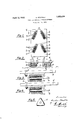
Figures 1 and 2 show a bottom and a side view of the arrangement of the knife rolls as adapted to a reciprocating movement of the tool.
Figures 3 and 4: show thesknife or cutter rolls in side views, both before the start and during working.
Figure 5 is a plan or top view of another constructional formof the cutter or knife discs. l
The tool itself is composed of'individual thinknife or cutting discs, which are assembled so as to form a rolllike unit.- They are arranged, one surface behind the other, loose and rotatable on the horizontal spindle b, and are-kept apart at the proper distance by means of intermediate discs or Washers-0, play being allowed between all of them.
These knife, or cutter rolls or spindles arearranged on sockets or brackets d, comprising a base which are moved to and fro, as shown by arrows in Figures 1 and 2, the movement being effected either mechanically or manui6 ally. It is preferable to arrange the cutter or knife rolls so that they are oblique to the direction of movement, and in such a manner that the individual rolls are disposed at an angle to each other. By meansof altering '10 the inclination as for instance by means of turningthem around the fixing bolt e serving as arota-tional pivot, it is possible to vary and adjust the thickness of the shavings i. e. the depth of thecut. The rolls may be positioned in relation to one another in any suitable manner.
According to the invention the knife or cutting discs a are mounted in such a manner on their spindle b, that by reason of allowing suliicient play, they automatically assume an oblique or inclined position as shown in Figure 4, and thus only work withone edge, which acts as a cutter. According to whether the tool is moved forwards or backwards, so '85 one or he other of the two cutting edges is at work alternately and by reason of this, and i also by reason of the very great thinness of the knife or cutterblade, the edges are continuously kept sharp.
The cutter or knife discs (1 may have any suitable or desired contour. In Figure 5 a triangle disc with rounded off corners is shown,this shape enabling the tool to smooth the surfaces right up to or nearly up to a vertical wall, as indicated in Figure 5, provided the knives or rolls are mounted sufficirlmtly far outwards on the socket or bracket i i What I claim is e 1. A tool for smoothing Wooden surfaces comprising a base; and a plurality of cutter rolls angularly mounted on said base relative to the direction of movement of the tool,
said rolls having cutters capable of assuming inclined position.
2. A tool for smoothing Wooden surfaces comprising a base; and a plurality of cutter rolls angularly mounted f on said base relative to the direction of movement of the tool,
. each roll having a plurality of spaced discs mounted on a spindle so that there is play between the discs to permit the discs to assume inclined positions.
3. A tool for smoothing Wooden surfaces comprising-a base; and a plurality of cutter rolls angularly mounted onsaid base relative to the direction of movement of the tool, each roll having a plurality of spaced discs mounted on a spindle and each disc being of polygonal form or contour.
In testimony whereof I have hereunto V signed my name.
GUSTAV STAEHLE.
Applications Claiming Priority (3)
| Application Number | Priority Date | Filing Date | Title |
|---|---|---|---|
| DE614453X | 1926-03-12 | ||
| DE1853470X | 1930-05-12 | ||
| DE358714X | 1930-05-12 |
Publications (1)
| Publication Number | Publication Date |
|---|---|
| US1853470A true US1853470A (en) | 1932-04-12 |
Family
ID=27193883
Family Applications (1)
| Application Number | Title | Priority Date | Filing Date |
|---|---|---|---|
| US487885A Expired - Lifetime US1853470A (en) | 1926-03-12 | 1930-10-10 | Tool for smoothing wooden surfaces |
Country Status (2)
| Country | Link |
|---|---|
| US (1) | US1853470A (en) |
| GB (1) | GB358714A (en) |
Cited By (1)
| Publication number | Priority date | Publication date | Assignee | Title |
|---|---|---|---|---|
| US2617223A (en) * | 1948-08-16 | 1952-11-11 | Davidson Plywood And Lumber Co | Machine for treating wood surfaces |
Families Citing this family (1)
| Publication number | Priority date | Publication date | Assignee | Title |
|---|---|---|---|---|
| DE4332781C1 (en) * | 1993-09-27 | 1995-01-12 | Babcock Bsh Ag | Device for smoothing a workpiece |
-
1930
- 1930-09-29 GB GB29170/30A patent/GB358714A/en not_active Expired
- 1930-10-10 US US487885A patent/US1853470A/en not_active Expired - Lifetime
Cited By (1)
| Publication number | Priority date | Publication date | Assignee | Title |
|---|---|---|---|---|
| US2617223A (en) * | 1948-08-16 | 1952-11-11 | Davidson Plywood And Lumber Co | Machine for treating wood surfaces |
Also Published As
| Publication number | Publication date |
|---|---|
| GB358714A (en) | 1931-10-15 |
Similar Documents
| Publication | Publication Date | Title |
|---|---|---|
| US2771111A (en) | Agitator and cutter unit for disintegrating food mixers | |
| US4046044A (en) | Paper trimmers | |
| US1853470A (en) | Tool for smoothing wooden surfaces | |
| US559179A (en) | Paper-cutting machine | |
| US1965501A (en) | Criss-cross slicing machine | |
| US2343616A (en) | Lawn and garden tool | |
| US3315452A (en) | Self-sharpening rotary mower blade | |
| US2924256A (en) | Vegetable slicer | |
| US2083848A (en) | Meat tendering device | |
| US2098865A (en) | Rotary file | |
| US2623416A (en) | Apparatus for serrating knife edges | |
| US4255992A (en) | Carpet cutting method | |
| JPS5924282Y2 (en) | Shredded katsuta in the cooker | |
| US2346046A (en) | Cutting machine | |
| CN102049799B (en) | Cutting depth adjusting device for milling type cutter of an electric planer | |
| US1431319A (en) | Machine for making wood fiber | |
| DE496507C (en) | Slicing machine with horizontally rotating circular knife | |
| US1478569A (en) | Portable planer | |
| JPH0135830Y2 (en) | ||
| US2809682A (en) | Wood slicing machines | |
| US1988482A (en) | Ice shaver | |
| JPH0221761B2 (en) | ||
| US290158A (en) | Cutter-head | |
| SU60087A1 (en) | Machine for splitting sugar tiles into pieces | |
| US1837014A (en) | Slicing machine |