US1853424A - Method and apparatus for treating material - Google Patents
Method and apparatus for treating material Download PDFInfo
- Publication number
- US1853424A US1853424A US433157A US43315730A US1853424A US 1853424 A US1853424 A US 1853424A US 433157 A US433157 A US 433157A US 43315730 A US43315730 A US 43315730A US 1853424 A US1853424 A US 1853424A
- Authority
- US
- United States
- Prior art keywords
- chamber
- conditioning
- gas
- water
- air
- Prior art date
- Legal status (The legal status is an assumption and is not a legal conclusion. Google has not performed a legal analysis and makes no representation as to the accuracy of the status listed.)
- Expired - Lifetime
Links
Images


Classifications
-
- C—CHEMISTRY; METALLURGY
- C14—SKINS; HIDES; PELTS; LEATHER
- C14B—MECHANICAL TREATMENT OR PROCESSING OF SKINS, HIDES OR LEATHER IN GENERAL; PELT-SHEARING MACHINES; INTESTINE-SPLITTING MACHINES
- C14B1/00—Manufacture of leather; Machines or devices therefor
-
- C—CHEMISTRY; METALLURGY
- C14—SKINS; HIDES; PELTS; LEATHER
- C14B—MECHANICAL TREATMENT OR PROCESSING OF SKINS, HIDES OR LEATHER IN GENERAL; PELT-SHEARING MACHINES; INTESTINE-SPLITTING MACHINES
- C14B2700/00—Mechanical treatment or processing of skins, hides or leather in general; Pelt-shearing machines; Making driving belts; Machines for splitting intestines
- C14B2700/28—Processes or apparatus for the mechanical treatment of hides or leather not provided for in groups C14B2700/01 - C14B2700/27
Definitions
- This invention relates'in general to the conditioning of materials and more particularly has reference to processes and apparatus for conditioning air and other gases which are circulated in contact with the material to be treated.
- the condition of the air or gas is modified by controlling its temperature and moisture contentand then the so-conditioned air is circulated in contact with the material to be treated.
- the material undergoing the conditioning treatment is usually placed in a products chamber through which the conditioned air is circulated, in such a manner that the moisture contained in the conditioned air will be taken up by the material undergoing treatment. It has been found that when the products chamber is provided with a roof which is at its inner ⁇ surface at a lower temperature than that of the conditioned air, condensation will take place and form droplets of moisture on the roof which will drop onto the material being treated. While the above circumstance does not affect certain materials, nevertheless, other materials are aii'ected in that when finished, they cont-ain spots where the condensed liquid has dropped thereon.
- a major object of this invention is to devise a. process and apparatus for treating materials with conditioned air or gases in which the material undergoing treatment will not be subjected to spotting.
- Another object of this invention is to devise methods and apparatus for treating materials with conditioned air in which the upper wall of the material conditioning chamber is heated to prevent condensation forming thereon.
- Yet another object of this invention is to devise methods and apparatus for treating materials in which the air is conditioned in various manners and in which the moisture content of the conditioned air is prevented from condensing on surfaces where the presence of condensation might damage the material treated.
- ⁇ Still another object of this invention is to devise an apparatus for conditioning materials provided with a products chamber having means in contact with the upper wall thereof for heatin the wall to prevent the moisture content o? the conditioned air from condensing on that wall.
- a further object of this invention is to provide an apparatus for treating materials in which the material is subjected to conditioned air Within a chamber, the upper wall of which ils contact with a tank containing heated lll
- a still further object of this invention is to provide an apparatus for treating materials with conditloned air in which the chamber for conditioning the material has a humidifying tank positioned thereabove in heat exchange contact with the upper wall of said chamber.
- material is treated by subjecting it to a conditioned gas.
- the gas may be conditioned as to humidity in accordance with any of a number of processes and after conditioning, is then passed through a chamber in contact with the material to be treated.
- the temperature of the upper wall of the chamber containing the material to be treated is maintained above the dew point of the conditioning gas.
- the upper wall may be directly heated, or a body of heated water may be maintained in contact therewith. The body of heated water may be employed solely for controlling the temperature of the upper wall of the products chamber or the water may be used to humidify the conditioning gas.
- water from the heated body of water maintained in contact with the u p'er wall of the material conditioning cham er may be continuously or intermittently withdrawn and supplied to a humidifying device maintained in the gas conditioning chamber.
- the gas may be conditioned by bringing it in contact with the body of water maintained in heat exchange relation with the upper wall of the material conditioning chamber.
- the condensation of moisture on the roof is prevented by circulatin or maintaining a heaed gas in contact wit the exterior of the roo It will be appreciated that other types of conditioning apparatus may be modified so as to fall within the scope of the present invention.
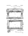
- Figure 1 is a somewhat diagrammatic representation of a material conditioning apparatus constructed in accordance with the present invention and which may be operated for effecting the process herein described.
- Figure 2 is a view similar to Fig. 1, showing a material conditioning apparatus slightly modified.
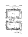
- Figure 3 is a diagrammatic representation of another form of material conditioning apparatus.
- Figure 4 is a perspective detail view of the Figure 7 is an illustration of a further l modified orm of the invention in which the roof is heated by means of a heated gas.
- an apparatus 1 for conditioning materials This appara-tus is divided by walls or artitions into a treatin or products cham er 2 and air conditioning chambers 3, 4, 5,6 and 7.
- Chamber 5 is in open communication with the side chamber or duct 4
- the lower chamber 6 is in open communication with the side chamber 7.
- Side chambers 4 and 7 communicate with the upper conditioning chamber 3 through openings, inv which are positioned fans 12, driven by electric motors 13'or other suitable sources of power.
- the upper conditioning chamber communicates with the lproducts chamber 2 through slots in the partition 10, and chambers 5 and 6 beneath partition 11 communicate with chamber 2 Ithrough similar slots in partition 11.
- slots 14 in the walls or partitions 10 and 11 are provided with adjustable closure members 15, which may be actuated to vary the size of the slot openings. It has been found that the size of the slot openings can be so regulated that air willI How through the roducts chamber in well-defined streams with practically no intermixing of the streams. This is very desirablesince, when the air flows in welldefined streams without any cross circuiting, an even distribution is obtained and proper treatment of all of the materials will be effected.
- Tube-like members 16 extend a predetermined distance above the partition 10 aid cooperate with the partition 10 and walls 8 and 9 to form tank structures in which are contained bodies of water 18.
- the drip guard deectors 17 extend above the tubes 16 varying distances, as is clearly shown in the drawings. These deliectors prevent any moisture which condenses on the upper wall 19 of the treatits ing apparatus from dripping through the slots 14 onto the material contained in the products chamber 2.
- the tank structures afforded by the several partitions 8, 9 and 10 and the tube structures 16 are provided with suitable overflow conduits 20, which serve to prevent water con tained in the tanks from exceeding a predetermined level.
- suitable heating elements 21 which may be in the form of coils through which hot iuids are circulated, or electrical f heating elements may be employed.
- Vater is supplied to the tanks above the slotted partition 10 by means of suitable supply conduits, (not shown), which preferably are fitted with valves controlled by automatic regulating devices, such as floats, positionedin the tank structures hereinbefore described. 'ith the construction just described, it will be appreciated that the Water within the tank structure will be maintained at a substantially constant level, regardless of the quantity of water evaporated therefrom by the heating elements.
- Chambers or ducts 5 and 6 beneath partition 11 are separated by the partition or separating wall 22.
- Each of these chambers is provided with a tank adapted to contain a body of water 23, which is prevented from exceeding a predetermined level by means of the overflow conduits 24.
- the bodies of water 23 are heated by means of heating elements 25, which are in the form of coils, through Which are circulated hot fluids, or elements through which electric current is passed.
- IVater is supplied to the lower tank structures by suitable supply conduits, (not shown), provided with automatically controlled valves for maintaining a predetermined level of water within the tanks.
- the temperature of the air may be increased, so that it will be greater than is desired in the products chamber.
- suitable cooling coils 26 in the side conditioning chambers 4 and 7. Water or other cooling media may be supplied to these coils through suitable conduits, (not shown), which are equipped with regulating valves.
- thermostatic control means may be provided in the products chamber 2, by means of which the valves positioned in the cool fluid supply conduits may be actuated. With such construction, the temperature of the air within the products chamber 2 can be automatically maintained at a predetermined value.
- Certain material may be advantageously treated by circulating saturated air thereover, which contains entrained moisture.
- Apparatus for introducing entrained Water in the air is shown in the drawings.
- a plurality of spraying means 27 of any construction and size found suitable for the purpose. As shown, the sprays are positioned above and below the cooling coils, Y
- the structure herein described is particularly useful for surface wetting the material to be treated. lVben so used, the moisture is evenly deposited on the material.
- wicks or submerged heaters can be used singly or together. These Wicks may be suspended from suitable racks 29 as shown in Fig. 4. V'Vhile wicks have been shown in the lower conditioning chamber, it should be understood that ⁇ they may also be employed in the upper humidifying chamber.
- the water in the tanks associated with the rocfs of the products chambers is maintained at a temperature equal to or above that at which moisture will condense from the conditioning gas.
- material ⁇ to be treated iS placed in the products chamber 2 and the fans 12 are set in operation so that air will flow over the material in the desired direction.
- Air in chamber 1, in one direction of How, will be drawn down through slots 14 in partition 11 over the bodies of water 23.
- These bodies of water may be heated at a confv stant rate or at a varying rate, dependent upon the manner in which the structure is to be operated. Vapors generated by heating the bodies of water 23 arise and diffuse into the air which flows through ducts 5 and 6.
- the temperature of the conditioning air may, of course, be regulated by controlling the temperature of the cooling coils and the temperature of the water entrained in the air, and by regulation of the heating elements in the conditioning chambers.
- the size of the slots 14 may be regulated by adjusting closures 15 so that the air will flow through the products chamber 2 in well-defined streams, So that material in all portions of the chamber will receive the proper treatment.
- FIG. 3 there is Shown a conditioning apparatus of the type set forth in my copending application Serial No. 81,606, filed January 15, 1926,
- this apparatus comprises a casing 3() divided by walls or partitions 31, 32 and 33, into a products chamber 34 and air conditioning chambers 35, 36 and 37.
- Partition 31 is provided with a plurality of openings, through which the gas may pass in circulating through the chambers.
- a fan or blower 38 is mounted in an opening in the partition 33 and is actuated by the power drive 39 or any other suitable means.
- the lower air conditioning chamber 36 In the lower air conditioning chamber 36 are positioned one or a plurality of water bodies 40 over which the gas is passed to humidify the same.
- a plurality of Wicks 28 are supported on rods 29 and dip in the water body 40.
- Water or other suitable liquid is supplied to the tank 42 in the chamber 86 in any desired manner, and the rate of supply may be controlled to effect the most advantageous operation.
- An outlet 43 is provided, which may be equipped with a liquid level regulating device for maintaining a constant level of liquid in the tanks 42.
- the gas is heated to a predetermined temperature by the heating elements 41 in chamber 35, and is then passed to chamber 36, where it becomes saturated with moisture. From chamber 36, the gas is drawn by the fan or blower 38 and is forced through chamber 34 in contact with the material to be treated. .f
- he present invention overcomes the above disadvantage by providing means for heating the'upper wall 44 so as to prevent the condensation of moisture thereon.
- One method of heating the upper wall is to place a tank 45 in heat exchange contact therewith, and to maintain a body of heated Water in the tank.
- tank 45 contains a body of water 46 which is connected with suitable automatically controlled supply conduits, (not shown), so that a sufficient quantity of water will always be present in the tank to insure the proper operation of the apparatus.
- Suitable heating elements 47 are submerged in the body of water 46 and are provided with automatically controlled mechanism ⁇ for maintaining definite water temperatures.
- the wall will bemaintained at a temperature substantially the same as that of the body of water, which temperature is equal or greater than that of the conditioninggas will prevent condensate forming on the wall.
- the heated water from the tank 45 can be withdrawn therefrom and passed through conduit 48 into the tank 42 at a rate which will compensate for the evaporation of liquid from the lower humidifying chamber.
- apparatus such as shown in Figures 1 and 2 may be modified so as to operate with only the bodies of Wat/er in the upper portion of the apparatus.
- This type of apparatus is clearly shown in my copending applications Serial Nos. 322,432 and 322,433, filed November 28, 1929.
- Apparatus such as set forth in the above mentioned copending applications may be advantageously em-l ployed for conditioning certain materials.
- This form of apparatus employs the heated bodies of water maintained in contact with the roof of the products chamber for two purposes, namely, to humidify7 the conditioning gas, and to prevent condensation of moisture contained in the conditioning gas on the undersurface of the roof of the products chamber.
- FIG. 5 there is shown a conditioning apparatus in which the means for heating the roof of the products chamber to prevent the condensation of moisture thereon also serves as the humidifier.
- this apparatus comprises a casing 49 divided by walls or partitions 50, 51 and 52 into a products chamber or compartment 53 and gas conditioning and circulating compartments 54, 55 and 56.
- Partition 50 is provided with a plurality of openings through which the conditioning gas may pass from the conditioning compartments into the products chamber 53.
- a fan or blower 57 is positioned for rotation in an opening formed in partition 51.
- the fan may be carried by shaft 58 which is rotated l by means of the pulley 59 and the power belt 60. Any suitable mounting for instance, the bearing bracket 58 may be provided. Of course, means other than those shown may be employed for rotating the fan.
- a fan guard 61 formed of suitable grating or screening may be provided to protect Workers who may enter the chamber 53, through doors (not shown) to place and remove material to be treated from the chamber.
- the heating elements may be of any desired construction and type, and may be operated in a manner most suitable for carrying out the treatment. It will be noted that the tank structure is arranged in heat conducting relation with the wall or roof 52, and consequently the roof will be at substantially the same temerature as the body of water or other liquid 1n the tank.
- Water or other liquid may be supplied to the roof tank in accordance with the quantity evaporated.
- the supply may be controlled by automatic control valves (not shown) which cooperate with liquid level control valves (also not shown) to maintain a predetermined quantityv of liquid in the tank structure.
- the conditioning gas is circulated by means of the fan or blowerver the body of water or other liquid in the tank and through the roducts chamber 53.
- the air or other gas In passing over the eated liquid, the air or other gas will take up the vapor arising from the liquid and will carry the same into the products chamber where it will be assimulated by the material undergoing treatment.
- the roof 52 Since the roof 52 is in thermal contact with the tank structure in which is contained heated liquid, and as the gas is conditioned both as to temperature and humidity by the heaters 63, the roof will be at a temperature approximately equal to that of the liquid and at a temperature higher than that of the conditioning gas, thus making impossible condensation of moisture thereon, and the disadvantages of having condensate form on the roof will be entirely avoided.
- the upper wall of the several forms of conditioning apparatus have been heated by means of heated bodies of water, I wish it to be clearly understood that any other means for maintaining the temperature of the upper wall sufiiciently high to prevent the condensation of moisture thereon may be employed.
- the upper wall may be heated yby direct contact with heating elements or any other heating medium.
- Fig. 6 shows an apparatus similar to that shown in Fig. 3, modified so that the roof may be hea-ted by a gas instead of a liquid. Parts shown in Fig. 6 similar to those shown in Fig. 3 have been designated by corresponding reference numerals.
- This device differs from that illustrated in Fig. 3, in that the upper liquidtankiseliminated.
- the upper portion of the products chamber is partitioned by the wall or secondary roof 65, to form a chamber 66 betyvggthe saine and the roof 64 of the treating apparatus.
- the partition 65 is preferably formed of metal or other material which is a fairly good conductor of heat.
- T'o prevent the condensation of moisture on the roof 65, it is necessar to maintain the temperature of the gas in t e chamber 66 at or above the temperature of the gas in the products chamber. For instance, if the temperature of the conditioning gas is 95 F. in the treating chamber, the temperature of the gas in the chamber 66 should be 95 F. or higher.
- the temperature of the gas in the chamber 66 may be regulated by manually controlling the operation of the heating elements 67 or it may be regulated by the automatic control device 68. In any event, the temperature is regulated so that condensation of moisture on the roof of the products chamber is prevented.
- FIG. 7 Another modification of the invention is shown in Fig. 7.
- This form of the invention is similar to that shown in Fig. 6, in that a gaseous iuid is employed as the medium for heating the roof of the products chamber.
- the structure of Fig. 7 differs from Fig. 6, in that in Fig. 7, there is a flow of gas in contact with the roof of the products chamber.
- Chamber 66 is in communication with the atmosphere at the ends of the apparatus.
- the openings at the ends of the chamber 66 serve as inlets for the heating gas.
- An outlet conduit 69 is arranged at the upper portion.- of the chamber, and is provided with a damper or valve 70 to control the outfiow of gas from chamber 66.
- the roof 71 of the chamber 66 is sloped from the inlets to the outlet 69.
- heating elements 72 Adjacent each inlet opening are heating elements 72, which heat the incoming air or other gas so that the fluid flowing incontact with the products chamber roof will be at a temperature suiiiciently high to prevent condensation of moisture on the inner surface thereof.
- the temperature of the gas may be controlled either by regulating the action of the heating element or by regulating the rate of flow through the chamber 66 by operating the valve or damper 70. This may be effected manually or automatically. As shown in the drawings, the iiow of gas through the compartment 66 is efl'ected by thermosiphonic action, but I wish it to be clearly understoodl that a blower or other type of gas forcing means may be employed to move the gas through the chamber 66.
- the heated gas passing from chamber 66 ditionin through conduit 69 may be used to advantage.
- the gas may be introduced in the conditioning apparatus and after humidiication may be passed in the products chamber.
- the gas after passing from the chamber 66 may be mixed with gas flowing in the treating apparatus or may be mixed With fresh gas as it is introduced into the treating apparatus.
- the heated gas from chamber 66 may be introduced into the concompartments of the treating apparatus efore the heating stage or between the heating sta e and the humidifying stage.
- the temperature is re lated so that moisture will not condense rom the conditioning gas on the roof of the products chamber.
- the present invention as hereinbefore set forth, is of decided advantage in that materials normally rendered valueless or of little value when spotted, may now be treated with a conditioned gas without danger of spotting.
- a method of conditioning material comprising circulating a conditioning gas through a chamber containing the material, subjecting the gas to contact with ay body of liquid positioned above the chamber, and
- a method of conditioning material comprising circulating a conditioning gas through a chamber containing the material, subjecting the gas to Contact with a body of Water and heating a body of water in contact with the upper wall of the chamber to prevent condensation of vapor from the gas on the upper Wall.
- a method of conditioning material comprising circulating a conditioning gas through a chamber containing the material, heating a body of liquid in contact with the upper wall of said chamber to prevent condensation of vapor from the gas on the upper a humidifyng zone and passing the gas into contact with the heated water to humidity the 4.
- a method of conditioning material comprising circulating a conditioning gas through a chamber containing the material, heating a body of liquid in contact with the upper wall of said chamber to prevent condensation of vapor from the gas on the upper wall, passing heated water from said body to a humidifying zone, heating the gas and assing it in contact with the heated water to umidify the gas.
- a method of conditioning material comprising passing a conditioning gas in contact with a body of water, drawing the gas from contact with the body of water, forcing it through a products chamber, maintaining a body of heated water in contact with the upper wall of said products chamber, and withdrawing water from said heated body to compensate for the water evaporated from the first body.
- a method of conditioning material comprising heating a conditioning gas, passing it in contact with a body of water, drawing the gas from contact with the body ot' water. tore ⁇ ing it through a products chamber. meintaining a body of heated water in contact with the upper wall ot' said products chamber. and withdrawing water from said heated body to compensate for the water evaporated from the first body.
- a method of conditioning material comprising circulatingr a conditioning gas from a zone containing the material to be treated. over a body of water, over a second body of water, then passing the gas into the zone containing the material to be treated, heating said second body of water to a temperature above that of the dew point ot said conditioning gas and transferring the heat of said second body of water to the upper wall of the zone containing the material to be treated.
- a method of conditioning material comprising circulating a conditioning gas through the chamber containing the material, subjecting the gas to contact with a body of water, suxbecting the gas to contact with a second bo y of water positioned above the chamber, and heating said second body of water to facilitate the humidification of the gas and transferring heat from the second body of Water to the upper wall of the chamber to prevent condensation of moisture on the upper portion of said chamber.
- a method of conditioning material comprising circulating a conditioning gas through a chamber containing the material, subjecting the gas to contact with a heated body of water, cooling the gas after humidification, and passing it in contact with a second body of heated water, the temperature to which said second body of water is heated being higher than that temperature at which moisture Will condense from a conditioning gas and transferring heat from the second body of water to the roof of the chamber to prevent condensation of moisture on the roof of the chamber.
- a method of conditioning material comprising circulating a conditioning gas through a chamber containing the material, subjecting the gas to contact with a heated body of water, cooling the gas after humidification and dispersing moisture therein, and passing it in contact with a second body of heated water, the temperature to which said second body of water is heated being higher than that temperature at which moisture will condense from a conditioning gas and conducting heat trom the second body of water to the roof of the chamber containing the material to prevent the condensation of moisture on the roof of the chamber.
- a conditioning apparatus comprising a chamber adapted to contain the material to be treated and a conditioning gas in contact therewith, a tank associated with the roof ot said chamber. a heating coil positioned in said tank ⁇ adapted to heat water therein so as to maintain the root1 of the chamber at a temperature above that at which moisture will condense from the conditioning gas.
- a conditioning apparatus comprising a products chamber, a plurality of gas-conditioning chambers arranged in parallel circuit with said products chamber, means for circulatin the gas through said products chamber 1n parallel circuits through said conditioning chambers, means in said conditioning chambers for humidifying the gas, said means comprising a heated body of water maintained in heat exchange relation with the upper wall of the products chamber to prevent condensation of moisture thereon.
- An apparatus for treating tobacco and similar materials comprising a products chamber having upper and lower slotted walls, conditioning chambers, a tank structure associated with the upper walls, a tank structure positioned beneath the lower wall, and means in the upper tank for heating water therein to prevent condensation on the ⁇ upper wall thereof. and consequent spotting of the material to be treated.
- An apparatus for treating tobacco and similar materials comprising a products chamber having upper and lower slotted walls, conditioning chambers, a' tank structure associated with the upper walls. a tank structure positioned beneath the lower walls, means positioned in said conditioning chambers for cooling air circulated therethrough, and means in the upper tank for heating water therein to prevent condensation on the upper wall thereof and consequent spotting of the material to be treated.
- An apparatus for treating tobacco and similar materials comprising a products chamber having upper and lower slotted Vs au walls, conditioning chambers, a tank structure associated with the upper walls, a tank structure positioned beneath the lower wall, means positioned in said conditioning chambers for cooling air circulated therethrou h, means associated with the cooling means or entraining water in the gas, and means in the upper tank for heating water therein to prevent condensation on th up er wall-thereof and consequent spotting o the material to be treated.
- An apparatus for conditioning material comprising a products chamber, an air heating chamber, a humidifying chamber, means for passing air through said chambers, and means assoclated with the roof of the products chamber for maintaining the wall at a temperature above the dew point of the air, said last mentioned means comprising a body of heated water.
- An apparatus for conditioning material comprising a products chamber, an air heating chamber, a humidiying chamber,
- said last mentioned means comprising a bod-y of heated water, and means for conveying heated water from the body to the humldifying chamber.
- An apparatus for conditioning ⁇ material comprising a roducts chamber, an air conditioning cham r, ahumidiying tank in the air conditioning chamber, means associated with the tank for increasing the effective area of water maintained therein, means for circulating air through said chambers, and means associated with the upper wall of the products chamber to prevent the formation of droplets of water thereon.
- An apparatus for conditioning material comprising a roducts chamber, an air conditioning cham er, a humidifying tank in the air conditioning chamber, means associated with the tank for increasing the effective area of water maintained therein, means for circulating air through said chambers, a body of water associated with the upper wall of the products chamber, means for heating said water to transfer heat to the upper wall to prevent condensation of moisture thereon.
- An apparatus for conditloning material comprising a products chamber, an air conditioning chamber, a humidifying tank in the air conditioning chamber, means assoheated body to the humidifyin tank to compensate for water evaporated t erefrom.
- a conditioning apparatus comprising a chamber adapted to contain the material to be treated and a conditioning gas in contact therewith, a compartment associated with the roof of said chamber, adapted to contain a iiuid therein, and means 1n said compartment for said Huid and temperature responsive means in the compartment for regulating the temperature of the fluid heating gas so as to prevent the condensation of moisture upon the roof of the chamber containing the material to 'be treated.
- a conditioning apparatus comprising a chamber adapted to contain material to be treated and a conditioning gas in contact therewith, a compartment associated with the roof of said chamber, heating means ositioned in said compartment adapted to eat gas therein, so as to maintain the roof of the chamber at a temperature above that at which moisture will condense from the conditioning 23.
- a conditioning apparatus comprising a chamber adapted to contain material to be treated and a conditioning gas in contact therewith, a compartment associated with the roof of said chamber, said compartment being closed to communication with the chamber and lhaving air inlets at the ends thereof, and an air outlet at the upper portion thereof, and means in said compartment for heating and circulatin air therethrough.
- a method of con itioning material y comprising heating a body of gas, passin said gas in contact with moisture saturated elements, passing the humidified gas into a chamber containing material to be treated, heatinga second body of gas, and passing it in contact with the roof of the chamber containing the material to be treated, and subsequently introducing said second body of gas after humidification into the chamber containing the material to be treated.
Description
April l2, 1932. G. D. HARRIS METHOD AND APPARATUS FOR TREATING MATERIAL Filed March 4, 1930 4 Sheets-Sheet momma April 12, 1932. G. D. HARRIS 1,853,424
METHOD AND APPARATUS FOR TREATING MATERIAL Filed March 4, 1930 4 Sheets-Sheet 2 aucun April l2, 1932.
Filed March 4, 1950 4 Sheets-Sheet 3 31a/vanto@ atta/mw April 12, 1932. G, D. HARR|S 1,853,424
METHOD AND APPARATUS FOR TREATING MATERIAL Filed March 4, 1930 4 Sheets-Sheet 4 57 29 Z? 4dV clummy Patented Apr. 12, 1932 UNITEDv STATES PATENT OFFICE GORDON DON HARRIS, F SOUND BEACH, CONNECTICUT, ASSIGNOR TO THE INDUS- TRIAL DRYER CORPORATION, OF STAMFORD, CONNECTICUT, A CORPORATION OF CONNECTICUT Y METHOD AND APPARATUS FOR TREATING .Application filed March 4, 1930. Serial No. 433,157.
This invention relates'in general to the conditioning of materials and more particularly has reference to processes and apparatus for conditioning air and other gases which are circulated in contact with the material to be treated.
' l`his application is a continuation in part v of my copending applications, Serial No.
81,606, filed January 15, 1926, Serial No. 322,432, filed November 28, 1928, and Serial No. 322,433, filed November 28, 1928.
In many industries in which materials are Worked and otherwise treated to form them into finished articles, it has been found that the workability of the material can be advantageously affected by subjecting the material to a conditioning process prior to subjecting it to any manipulation to form it into a finished article.
In certain processes heretofore used for conditioning various materials, the condition of the air or gas is modified by controlling its temperature and moisture contentand then the so-conditioned air is circulated in contact with the material to be treated. The material undergoing the conditioning treatment is usually placed in a products chamber through which the conditioned air is circulated, in such a manner that the moisture contained in the conditioned air will be taken up by the material undergoing treatment. It has been found that when the products chamber is provided with a roof which is at its inner` surface at a lower temperature than that of the conditioned air, condensation will take place and form droplets of moisture on the roof which will drop onto the material being treated. While the above circumstance does not affect certain materials, nevertheless, other materials are aii'ected in that when finished, they cont-ain spots where the condensed liquid has dropped thereon.
It will be appreciated that in the case of treating materials which should have an unspotted appearance when finished, the above disadvantage is undesirable. The present invention contemplates improvements in the conditioning processes and apparatus which will avoid the disadvantageous spotting of 'thc material discussed above.
A major object of this invention is to devise a. process and apparatus for treating materials with conditioned air or gases in which the material undergoing treatment will not be subjected to spotting.
Another object of this invention is to devise methods and apparatus for treating materials with conditioned air in which the upper wall of the material conditioning chamber is heated to prevent condensation forming thereon.
Yet another object of this invention is to devise methods and apparatus for treating materials in which the air is conditioned in various manners and in which the moisture content of the conditioned air is prevented from condensing on surfaces where the presence of condensation might damage the material treated.
`Still another object of this invention is to devise an apparatus for conditioning materials provided with a products chamber having means in contact with the upper wall thereof for heatin the wall to prevent the moisture content o? the conditioned air from condensing on that wall.
A further object of this invention is to provide an apparatus for treating materials in which the material is subjected to conditioned air Within a chamber, the upper wall of which ils contact with a tank containing heated lll A still further object of this invention is to provide an apparatus for treating materials with conditloned air in which the chamber for conditioning the material has a humidifying tank positioned thereabove in heat exchange contact with the upper wall of said chamber.
With these and other objects in view, which may be incident to my improvements, the invention consists in the parts and combinations to be hereinafter set forth and claimed, with the understanding that the several necessary elements comprising my invention may be varied in construction, proportions and arrangement without departing from the spirit and scope of the appended claims.
In accordance with the present invention, material is treated by subjecting it to a conditioned gas. The gas may be conditioned as to humidity in accordance with any of a number of processes and after conditioning, is then passed through a chamber in contact with the material to be treated. In order to prevent spotting of the material undergoing treatment, due to condensed liquids falling thereon, the temperature of the upper wall of the chamber containing the material to be treated, is maintained above the dew point of the conditioning gas. In order to maintain thetemperature of the upper wall of the material conditioning chamber above that at which moisture condenses from the conditioning gas, the upper wall may be directly heated, or a body of heated water may be maintained in contact therewith. The body of heated water may be employed solely for controlling the temperature of the upper wall of the products chamber or the water may be used to humidify the conditioning gas.
In accordance with one process and the apparatus for carrying it out, water from the heated body of water maintained in contact with the u p'er wall of the material conditioning cham er may be continuously or intermittently withdrawn and supplied to a humidifying device maintained in the gas conditioning chamber. f
In another form of the invention, the gas may be conditioned by bringing it in contact with the body of water maintained in heat exchange relation with the upper wall of the material conditioning chamber.
In a further modification of the invention, the condensation of moisture on the roof is prevented by circulatin or maintaining a heaed gas in contact wit the exterior of the roo It will be appreciated that other types of conditioning apparatus may be modified so as to fall within the scope of the present invention.
In order to make my invention more clearly understood, I have shown in the accompanying drawings, means for carrying the same into practical effect without limiting the `improvements in their useful applications to the particular constructions which, for the purpose of explanation, have been made the subject of illustration.
f In the drawings:
Figure 1 is a somewhat diagrammatic representation of a material conditioning apparatus constructed in accordance with the present invention and which may be operated for effecting the process herein described.
Figure 2 is a view similar to Fig. 1, showing a material conditioning apparatus slightly modified.
Figure 3 is a diagrammatic representation of another form of material conditioning apparatus.
' Figure 4 is a perspective detail view of the Figure 7 is an illustration of a further l modified orm of the invention in which the roof is heated by means of a heated gas.
In the drawings, there is shown an apparatus 1 for conditioning materials. This appara-tus is divided by walls or artitions into a treatin or products cham er 2 and air conditioning chambers 3, 4, 5,6 and 7. The
vertical partitions or walls 8 and 9 separate chamber 2 from the side conditioning chambers or ducts 4 and 7, respectively, and horizontal partitions 10 and 11 separate chamber 2 from the upper and lowerconditioning chambers. Chamber 5 is in open communication with the side chamber or duct 4, and the lower chamber 6 is in open communication with the side chamber 7. Side chambers 4 and 7 communicate with the upper conditioning chamber 3 through openings, inv which are positioned fans 12, driven by electric motors 13'or other suitable sources of power. The upper conditioning chamber communicates with the lproducts chamber 2 through slots in the partition 10, and chambers 5 and 6 beneath partition 11 communicate with chamber 2 Ithrough similar slots in partition 11.
In order to secure an even distribution of air through the products chamber 2, slots 14 in the walls or partitions 10 and 11 are provided with adjustable closure members 15, which may be actuated to vary the size of the slot openings. It has been found that the size of the slot openings can be so regulated that air willI How through the roducts chamber in well-defined streams with practically no intermixing of the streams. This is very desirablesince, when the air flows in welldefined streams without any cross circuiting, an even distribution is obtained and proper treatment of all of the materials will be effected.
The tank structures afforded by the several partitions 8, 9 and 10 and the tube structures 16 are provided with suitable overflow conduits 20, which serve to prevent water con tained in the tanks from exceeding a predetermined level. Submerged in the bodies of Water 18 are suitable heating elements 21, which may be in the form of coils through which hot iuids are circulated, or electrical f heating elements may be employed. Vater is supplied to the tanks above the slotted partition 10 by means of suitable supply conduits, (not shown), which preferably are fitted with valves controlled by automatic regulating devices, such as floats, positionedin the tank structures hereinbefore described. 'ith the construction just described, it will be appreciated that the Water within the tank structure will be maintained at a substantially constant level, regardless of the quantity of water evaporated therefrom by the heating elements.
Chambers or ducts 5 and 6 beneath partition 11 are separated by the partition or separating wall 22. Each of these chambers is provided with a tank adapted to contain a body of water 23, which is prevented from exceeding a predetermined level by means of the overflow conduits 24. The bodies of water 23 are heated by means of heating elements 25, which are in the form of coils, through Which are circulated hot fluids, or elements through which electric current is passed. IVater is supplied to the lower tank structures by suitable supply conduits, (not shown), provided with automatically controlled valves for maintaining a predetermined level of water within the tanks.
It will be appreciated that after the vapors arising from the bodies of Water diffuse into the air, the temperature of the air may be increased, so that it will be greater than is desired in the products chamber. In order to cool the air so that it will be at the proper temperature for treating the material in the products chamber, there are provided suitable cooling coils 26 in the side conditioning chambers 4 and 7. Water or other cooling media may be supplied to these coils through suitable conduits, (not shown), which are equipped with regulating valves. If desired, thermostatic control means may be provided in the products chamber 2, by means of which the valves positioned in the cool fluid supply conduits may be actuated. With such construction, the temperature of the air within the products chamber 2 can be automatically maintained at a predetermined value.
Certain material may be advantageously treated by circulating saturated air thereover, which contains entrained moisture. Apparatus for introducing entrained Water in the air is shown in the drawings. In each of the compartments 4 and 7, there are positioned a plurality of spraying means 27 of any construction and size found suitable for the purpose. As shown, the sprays are positioned above and below the cooling coils, Y
but I wish it to be clearly understood that the sprays may be located at any point found desirable, and that any number of them may be employed.
It is within the concept of the present invention to regulate the temperature of the water supplied to the spraying devices so that the temperature of the air may be properly maintained.
The structure herein described is particularly useful for surface wetting the material to be treated. lVben so used, the moisture is evenly deposited on the material.
The structure illustrated in Fig. 2 is of substantially the same constructionas the apparatus shown in Fig. 1 and similar parts in each ligure have been designated by corresponding reference numerals. As shown in Fig. 2, either wicks or submerged heaters can be used singly or together. These Wicks may be suspended from suitable racks 29 as shown in Fig. 4. V'Vhile wicks have been shown in the lower conditioning chamber, it should be understood that` they may also be employed in the upper humidifying chamber.
In the structure shown in Figures 1 and 2, the water in the tanks associated with the rocfs of the products chambers, is maintained at a temperature equal to or above that at which moisture will condense from the conditioning gas.
By maintaining the temperature of the water in the tanks associated with the partitions 10 at a temperature equalto or abovethat at which moisture will condense fromv the conditioning gas, the hereinbefore pointed out disadvantage is avoided. By maintainying the temperature of the partition 10,
either equal to or above that ofthe conditioning gas, due to the heat exchange between the heated body of water and the partition 10, there will be no condensate formed or. the underside of the partition 10. It will bey appreciated that as there is no condensate formed on the undersurface of the partition 10, there will be no possibility of the material, undergoing treatment becoming spotted as the result of condensate dripping from the roof of the products chamber.
In operation, material `to be treated iS placed in the products chamber 2, and the fans 12 are set in operation so that air will flow over the material in the desired direction. Air in chamber 1, in one direction of How, will be drawn down through slots 14 in partition 11 over the bodies of water 23. These bodies of water may be heated at a confv stant rate or at a varying rate, dependent upon the manner in which the structure is to be operated. Vapors generated by heating the bodies of water 23 arise and diffuse into the air which flows through ducts 5 and 6.
Mixtures of air and vapors flow up through ducts 4 and 7 over the cooling coils 26. The temperature of the cooling coils is maintained by a thermostat within the products chamber, or elesewhere, so that the air flowing over the coils will be at such a tempera ture that, after further treatment, it will be at the temperature desired for the products chamber. Before and/or after the cooling treatment, water from the spraying devices may be dispersed int-o the air. This water is entrained in the air and is carried with the air over the material to be treated. The tempered air from the ducts 7 and 8, which is substantially saturated with moisture, is then drawn upwardly by the fans 12 and is forced into chamber 3, where it meets with vapors arising from the bodies of water 18. Vapors arising from the bodies of water 18 will diffuse into the air in the chamber 3 to further moisten the same. After this treat.- ment, the air will be substantially saturated. The treated air will then flow down through the slots 14 over the material to be treated.
The temperature of the conditioning air may, of course, be regulated by controlling the temperature of the cooling coils and the temperature of the water entrained in the air, and by regulation of the heating elements in the conditioning chambers.
As hereinbefore pointed out, the size of the slots 14 may be regulated by adjusting closures 15 so that the air will flow through the products chamber 2 in well-defined streams, So that material in all portions of the chamber will receive the proper treatment.
The present invention is applicable to other types of conditioning apparatus. In Fig. 3, there is Shown a conditioning apparatus of the type set forth in my copending application Serial No. 81,606, filed January 15, 1926,
modified in accordance with the present invention. As illustrated in the drawings, this apparatus comprises a casing 3() divided by walls or partitions 31, 32 and 33, into a products chamber 34 and air conditioning chambers 35, 36 and 37. Partition 31 is provided with a plurality of openings, through which the gas may pass in circulating through the chambers. A fan or blower 38 is mounted in an opening in the partition 33 and is actuated by the power drive 39 or any other suitable means.
In the lower air conditioning chamber 36 are positioned one or a plurality of water bodies 40 over which the gas is passed to humidify the same. A plurality of Wicks 28 are supported on rods 29 and dip in the water body 40.
Water or other suitable liquid is supplied to the tank 42 in the chamber 86 in any desired manner, and the rate of supply may be controlled to effect the most advantageous operation. An outlet 43 is provided, which may be equipped with a liquid level regulating device for maintaining a constant level of liquid in the tanks 42.
In operation, the gas is heated to a predetermined temperature by the heating elements 41 in chamber 35, and is then passed to chamber 36, where it becomes saturated with moisture. From chamber 36, the gas is drawn by the fan or blower 38 and is forced through chamber 34 in contact with the material to be treated. .f
As hereinbefore mentioned, there is a tendency for the moisture which saturates the conditioning gas, to condense out upon contact of the conditioning gas with cold surfaces. For instance, if the upper wall 44 of the conditioning chamber were cold, globules of liquid would form on the undersurface thereon, and when the globules obtain a weight sufficient to overcome the adhesion between the globules and the undersurface of the roof, the liquid would fall onto the material and spot it.
'I he present invention overcomes the above disadvantage by providing means for heating the'upper wall 44 so as to prevent the condensation of moisture thereon. One method of heating the upper wall is to place a tank 45 in heat exchange contact therewith, and to maintain a body of heated Water in the tank. y As is clearly shown in Fig. 3, tank 45 contains a body of water 46 which is connected with suitable automatically controlled supply conduits, (not shown), so that a sufficient quantity of water will always be present in the tank to insure the proper operation of the apparatus. Suitable heating elements 47 are submerged in the body of water 46 and are provided with automatically controlled mechanism` for maintaining definite water temperatures. It will be readily understood that by maintaining a body of heated water in heat exchange relation with the upper wall 44, the wall will bemaintained at a temperature substantially the same as that of the body of water, which temperature is equal or greater than that of the conditioninggas will prevent condensate forming on the wall.
If found desirable, the heated water from the tank 45, can be withdrawn therefrom and passed through conduit 48 into the tank 42 at a rate which will compensate for the evaporation of liquid from the lower humidifying chamber.
If desired, apparatus such as shown in Figures 1 and 2 may be modified so as to operate with only the bodies of Wat/er in the upper portion of the apparatus. This type of apparatus is clearly shown in my copending applications Serial Nos. 322,432 and 322,433, filed November 28, 1929. Apparatus such as set forth in the above mentioned copending applications may be advantageously em-l ployed for conditioning certain materials. In this particular type of apparatus, it will be appreciated that there will be no condensation of the moisture from the conditioning gas formed on the undersurface of the roof of the products chamber. This form of apparatus employs the heated bodies of water maintained in contact with the roof of the products chamber for two purposes, namely, to humidify7 the conditioning gas, and to prevent condensation of moisture contained in the conditioning gas on the undersurface of the roof of the products chamber.
In Fig. 5, there is shown a conditioning apparatus in which the means for heating the roof of the products chamber to prevent the condensation of moisture thereon also serves as the humidifier. As illustrated in Fig. 5, this apparatus comprises a casing 49 divided by walls or partitions 50, 51 and 52 into a products chamber or compartment 53 and gas conditioning and circulating compartments 54, 55 and 56. Partition 50 is provided with a plurality of openings through which the conditioning gas may pass from the conditioning compartments into the products chamber 53. A fan or blower 57 is positioned for rotation in an opening formed in partition 51. The fan may be carried by shaft 58 which is rotated l by means of the pulley 59 and the power belt 60. Any suitable mounting for instance, the bearing bracket 58 may be provided. Of course, means other than those shown may be employed for rotating the fan.
' As a feature of safety, a fan guard 61 formed of suitable grating or screening may be provided to protect Workers who may enter the chamber 53, through doors (not shown) to place and remove material to be treated from the chamber.
Positioned on the roof 52 are one or more tanks 62 containing liquid and equipped with heating elements 63. As in the other modifications herein described, the heating elements may be of any desired construction and type, and may be operated in a manner most suitable for carrying out the treatment. It will be noted that the tank structure is arranged in heat conducting relation with the wall or roof 52, and consequently the roof will be at substantially the same temerature as the body of water or other liquid 1n the tank.
Water or other liquid may be supplied to the roof tank in accordance with the quantity evaporated. The supply may be controlled by automatic control valves (not shown) which cooperate with liquid level control valves (also not shown) to maintain a predetermined quantityv of liquid in the tank structure.
In operation, the conditioning gas is circulated by means of the fan or blowerver the body of water or other liquid in the tank and through the roducts chamber 53. In passing over the eated liquid, the air or other gas will take up the vapor arising from the liquid and will carry the same into the products chamber where it will be assimulated by the material undergoing treatment.
Since the roof 52 is in thermal contact with the tank structure in which is contained heated liquid, and as the gas is conditioned both as to temperature and humidity by the heaters 63, the roof will be at a temperature approximately equal to that of the liquid and at a temperature higher than that of the conditioning gas, thus making impossible condensation of moisture thereon, and the disadvantages of having condensate form on the roof will be entirely avoided.
The present invention has been illustrated in the drawings as applied to several forms of conditioning apparatus, but I wish it to be clearly understood that the concept maintaining the temperature of the roof of the products chamber at a temperature equal to or greater than that of the conditioning gas may be applied to any type of material conditioning device, whether associated with a gas conditioning apparatus or not.
lVhile in the foregoing disclosure, the upper wall of the several forms of conditioning apparatus have been heated by means of heated bodies of water, I wish it to be clearly understood that any other means for maintaining the temperature of the upper wall sufiiciently high to prevent the condensation of moisture thereon may be employed. For instance, the upper wall may be heated yby direct contact with heating elements or any other heating medium.
In Figures 6 and 7, I have shown a construction which differs from that described in the foregoing disclosure in that the temperature of the roof of the products chamber is maintained above that at which moisture from the gas will condense thereon, by means of a heated gas instead of heated liquid.
Fig. 6 shows an apparatus similar to that shown in Fig. 3, modified so that the roof may be hea-ted by a gas instead of a liquid. Parts shown in Fig. 6 similar to those shown in Fig. 3 have been designated by corresponding reference numerals. This device differs from that illustrated in Fig. 3, in that the upper liquidtankiseliminated. The upper portion of the products chamber is partitioned by the wall or secondary roof 65, to form a chamber 66 betyvggthe saine and the roof 64 of the treating apparatus. The partition 65 is preferably formed of metal or other material which is a fairly good conductor of heat.
It will be appreciated that if a hot Huid is in contact with partition 65, and its temperature is sufliciently high, no moisture will condense on the interior surface of the partition or roof 65. This is accomplished in this form of the invention, by placing heat-Y ing elements 67 in chamber 66 to heat the gas therein, which in turn heats the partition or roof 65.
T'o prevent the condensation of moisture on the roof 65, it is necessar to maintain the temperature of the gas in t e chamber 66 at or above the temperature of the gas in the products chamber. For instance, if the temperature of the conditioning gas is 95 F. in the treating chamber, the temperature of the gas in the chamber 66 should be 95 F. or higher.
The temperature of the gas in the chamber 66 may be regulated by manually controlling the operation of the heating elements 67 or it may be regulated by the automatic control device 68. In any event, the temperature is regulated so that condensation of moisture on the roof of the products chamber is prevented.
Another modification of the invention is shown in Fig. 7. This form of the invention is similar to that shown in Fig. 6, in that a gaseous iuid is employed as the medium for heating the roof of the products chamber. The structure of Fig. 7 differs from Fig. 6, in that in Fig. 7, there is a flow of gas in contact with the roof of the products chamber.
As illustrated in Fig. 7, there is a compartment or chamber 66 formed 'above the roof 65. Chamber 66 is in communication with the atmosphere at the ends of the apparatus. The openings at the ends of the chamber 66 serve as inlets for the heating gas. An outlet conduit 69 is arranged at the upper portion.- of the chamber, and is provided with a damper or valve 70 to control the outfiow of gas from chamber 66. To facilitate the ow of gas, the roof 71 of the chamber 66 is sloped from the inlets to the outlet 69.
Adjacent each inlet opening are heating elements 72, which heat the incoming air or other gas so that the fluid flowing incontact with the products chamber roof will be at a temperature suiiiciently high to prevent condensation of moisture on the inner surface thereof.
4 The temperature of the gas ma be controlled either by regulating the action of the heating element or by regulating the rate of flow through the chamber 66 by operating the valve or damper 70. This may be effected manually or automatically. As shown in the drawings, the iiow of gas through the compartment 66 is efl'ected by thermosiphonic action, but I wish it to be clearly understoodl that a blower or other type of gas forcing means may be employed to move the gas through the chamber 66.
If found convenient or economical, the heated gas passing from chamber 66 ditionin through conduit 69, may be used to advantage. For instance, the gas may be introduced in the conditioning apparatus and after humidiication may be passed in the products chamber. The gas after passing from the chamber 66 may be mixed with gas flowing in the treating apparatus or may be mixed With fresh gas as it is introduced into the treating apparatus. The heated gas from chamber 66 may be introduced into the concompartments of the treating apparatus efore the heating stage or between the heating sta e and the humidifying stage. In this form 0I the invention, the temperature is re lated so that moisture will not condense rom the conditioning gas on the roof of the products chamber. Y
The present invention as hereinbefore set forth, is of decided advantage in that materials normally rendered valueless or of little value when spotted, may now be treated with a conditioned gas without danger of spotting.
The elimination of spotting of the material i is highly desirable when the apparatus is used for treating fancy leather goods and other materials which must have a pleasing finished appearance, or for treating materials, the quality of which would be detrimentally affected by spotting. y
While I have shown and described the preferred embodiment of my invention, I wish it to be understood that I do not confine myself to the precise details of construction herein set forth, by Way of illustration, as it is apparent that many changes and variations may be made therein, by those skilled in the art, without departing from the spirit of the invention, or exceeding the scope of the appended claims.
I claim:
1. A method of conditioning material comprising circulating a conditioning gas through a chamber containing the material, subjecting the gas to contact with ay body of liquid positioned above the chamber, and
'heating the body of liquid to diffuse moisture into the gas and to prevent condensation of noisture on the upper portion of said cham- 2. A method of conditioning material comprising circulating a conditioning gas through a chamber containing the material, subjecting the gas to Contact with a body of Water and heating a body of water in contact with the upper wall of the chamber to prevent condensation of vapor from the gas on the upper Wall.
3. A method of conditioning material comprising circulating a conditioning gas through a chamber containing the material, heating a body of liquid in contact with the upper wall of said chamber to prevent condensation of vapor from the gas on the upper a humidifyng zone and passing the gas into contact with the heated water to humidity the 4. A method of conditioning material comprising circulating a conditioning gas through a chamber containing the material, heating a body of liquid in contact with the upper wall of said chamber to prevent condensation of vapor from the gas on the upper wall, passing heated water from said body to a humidifying zone, heating the gas and assing it in contact with the heated water to umidify the gas.
5. A method of conditioning material comprising passing a conditioning gas in contact with a body of water, drawing the gas from contact with the body of water, forcing it through a products chamber, maintaining a body of heated water in contact with the upper wall of said products chamber, and withdrawing water from said heated body to compensate for the water evaporated from the first body.
6. A method of conditioning material comprising heating a conditioning gas, passing it in contact with a body of water, drawing the gas from contact with the body ot' water. tore` ing it through a products chamber. meintaining a body of heated water in contact with the upper wall ot' said products chamber. and withdrawing water from said heated body to compensate for the water evaporated from the first body.
7. A method of conditioning material comprising circulatingr a conditioning gas from a zone containing the material to be treated. over a body of water, over a second body of water, then passing the gas into the zone containing the material to be treated, heating said second body of water to a temperature above that of the dew point ot said conditioning gas and transferring the heat of said second body of water to the upper wall of the zone containing the material to be treated.
8. A method of conditioning material comprising circulating a conditioning gas through the chamber containing the material, subjecting the gas to contact with a body of water, suxbecting the gas to contact with a second bo y of water positioned above the chamber, and heating said second body of water to facilitate the humidification of the gas and transferring heat from the second body of Water to the upper wall of the chamber to prevent condensation of moisture on the upper portion of said chamber.
9. A method of conditioning material comprising circulating a conditioning gas through a chamber containing the material, subjecting the gas to contact with a heated body of water, cooling the gas after humidification, and passing it in contact with a second body of heated water, the temperature to which said second body of water is heated being higher than that temperature at which moisture Will condense from a conditioning gas and transferring heat from the second body of water to the roof of the chamber to prevent condensation of moisture on the roof of the chamber.
10. A method of conditioning material comprising circulating a conditioning gas through a chamber containing the material, subjecting the gas to contact with a heated body of water, cooling the gas after humidification and dispersing moisture therein, and passing it in contact with a second body of heated water, the temperature to which said second body of water is heated being higher than that temperature at which moisture will condense from a conditioning gas and conducting heat trom the second body of water to the roof of the chamber containing the material to prevent the condensation of moisture on the roof of the chamber.
11. A conditioning apparatus comprising a chamber adapted to contain the material to be treated and a conditioning gas in contact therewith, a tank associated with the roof ot said chamber. a heating coil positioned in said tank`adapted to heat water therein so as to maintain the root1 of the chamber at a temperature above that at which moisture will condense from the conditioning gas.
12. A conditioning apparatus comprising a products chamber, a plurality of gas-conditioning chambers arranged in parallel circuit with said products chamber, means for circulatin the gas through said products chamber 1n parallel circuits through said conditioning chambers, means in said conditioning chambers for humidifying the gas, said means comprising a heated body of water maintained in heat exchange relation with the upper wall of the products chamber to prevent condensation of moisture thereon.
13. An apparatus for treating tobacco and similar materials comprising a products chamber having upper and lower slotted walls, conditioning chambers, a tank structure associated with the upper walls, a tank structure positioned beneath the lower wall, and means in the upper tank for heating water therein to prevent condensation on the` upper wall thereof. and consequent spotting of the material to be treated.
14. An apparatus for treating tobacco and similar materials comprising a products chamber having upper and lower slotted walls, conditioning chambers, a' tank structure associated with the upper walls. a tank structure positioned beneath the lower walls, means positioned in said conditioning chambers for cooling air circulated therethrough, and means in the upper tank for heating water therein to prevent condensation on the upper wall thereof and consequent spotting of the material to be treated.
15. An apparatus for treating tobacco and similar materials comprising a products chamber having upper and lower slotted Vs au walls, conditioning chambers, a tank structure associated with the upper walls, a tank structure positioned beneath the lower wall, means positioned in said conditioning chambers for cooling air circulated therethrou h, means associated with the cooling means or entraining water in the gas, and means in the upper tank for heating water therein to prevent condensation on th up er wall-thereof and consequent spotting o the material to be treated.
16. An apparatus for conditioning material comprising a products chamber, an air heating chamber, a humidifying chamber, means for passing air through said chambers, and means assoclated with the roof of the products chamber for maintaining the wall at a temperature above the dew point of the air, said last mentioned means comprising a body of heated water.
17. An apparatus for conditioning material comprising a products chamber, an air heating chamber, a humidiying chamber,
-ineans for passing air through said chambers, g
and means associated with the roof of the products chamber for maintaining the wall at a temperature above -the dew `point of the air, said last mentioned means comprising a bod-y of heated water, and means for conveying heated water from the body to the humldifying chamber.
18. An apparatus for conditioning` material comprising a roducts chamber, an air conditioning cham r, ahumidiying tank in the air conditioning chamber, means associated with the tank for increasing the effective area of water maintained therein, means for circulating air through said chambers, and means associated with the upper wall of the products chamber to prevent the formation of droplets of water thereon.
19. An apparatus for conditioning material comprising a roducts chamber, an air conditioning cham er, a humidifying tank in the air conditioning chamber, means associated with the tank for increasing the effective area of water maintained therein, means for circulating air through said chambers, a body of water associated with the upper wall of the products chamber, means for heating said water to transfer heat to the upper wall to prevent condensation of moisture thereon.
20. An apparatus for conditloning material comprising a products chamber, an air conditioning chamber, a humidifying tank in the air conditioning chamber, means assoheated body to the humidifyin tank to compensate for water evaporated t erefrom.
21. A conditioning apparatus comprising a chamber adapted to contain the material to be treated and a conditioning gas in contact therewith, a compartment associated with the roof of said chamber, adapted to contain a iiuid therein, and means 1n said compartment for said Huid and temperature responsive means in the compartment for regulating the temperature of the fluid heating gas so as to prevent the condensation of moisture upon the roof of the chamber containing the material to 'be treated.
22. A conditioning apparatus comprising a chamber adapted to contain material to be treated and a conditioning gas in contact therewith, a compartment associated with the roof of said chamber, heating means ositioned in said compartment adapted to eat gas therein, so as to maintain the roof of the chamber at a temperature above that at which moisture will condense from the conditioning 23. A conditioning apparatus comprising a chamber adapted to contain material to be treated and a conditioning gas in contact therewith, a compartment associated with the roof of said chamber, said compartment being closed to communication with the chamber and lhaving air inlets at the ends thereof, and an air outlet at the upper portion thereof, and means in said compartment for heating and circulatin air therethrough.
24. A method of con itioning material y comprising heating a body of gas, passin said gas in contact with moisture saturated elements, passing the humidified gas into a chamber containing material to be treated, heatinga second body of gas, and passing it in contact with the roof of the chamber containing the material to be treated, and subsequently introducing said second body of gas after humidification into the chamber containing the material to be treated.
In testimony whereof I atiix my signature.
GORDON DON HARRIS.
ciated with the tank for increasing the eiective area of water maintained therein, means for circulating air through said chambers, a body of water associated with the upper wall of the products chamber, means for heating said water to transfer heat to the upper wall to prevent condensation of moisture thereon, and means for conducting water from said
Priority Applications (1)
| Application Number | Priority Date | Filing Date | Title |
|---|---|---|---|
| US433157A US1853424A (en) | 1930-03-04 | 1930-03-04 | Method and apparatus for treating material |
Applications Claiming Priority (1)
| Application Number | Priority Date | Filing Date | Title |
|---|---|---|---|
| US433157A US1853424A (en) | 1930-03-04 | 1930-03-04 | Method and apparatus for treating material |
Publications (1)
| Publication Number | Publication Date |
|---|---|
| US1853424A true US1853424A (en) | 1932-04-12 |
Family
ID=23719053
Family Applications (1)
| Application Number | Title | Priority Date | Filing Date |
|---|---|---|---|
| US433157A Expired - Lifetime US1853424A (en) | 1930-03-04 | 1930-03-04 | Method and apparatus for treating material |
Country Status (1)
| Country | Link |
|---|---|
| US (1) | US1853424A (en) |
Cited By (7)
| Publication number | Priority date | Publication date | Assignee | Title |
|---|---|---|---|---|
| US2453859A (en) * | 1944-12-13 | 1948-11-16 | Merlin L Pugh | Clothes drier |
| US2484527A (en) * | 1945-02-01 | 1949-10-11 | Thomas H Rhoads | Method and apparatus for control of humidity |
| US2545052A (en) * | 1947-11-17 | 1951-03-13 | William G Sebold | Egg cooler |
| US2590295A (en) * | 1948-01-23 | 1952-03-25 | Avco Mfg Corp | Clothes drier |
| US2753164A (en) * | 1952-10-31 | 1956-07-03 | Norman R Miller | Humidity chamber |
| US2856174A (en) * | 1953-12-14 | 1958-10-14 | Surface Combustion Corp | Continuous, circulating atmosphere glass furnace |
| US5294235A (en) * | 1991-09-25 | 1994-03-15 | Stuetzle Hugo | Device for the supply, distribution and moistening of gas in a gas-cleaning or decomposition installation |
-
1930
- 1930-03-04 US US433157A patent/US1853424A/en not_active Expired - Lifetime
Cited By (7)
| Publication number | Priority date | Publication date | Assignee | Title |
|---|---|---|---|---|
| US2453859A (en) * | 1944-12-13 | 1948-11-16 | Merlin L Pugh | Clothes drier |
| US2484527A (en) * | 1945-02-01 | 1949-10-11 | Thomas H Rhoads | Method and apparatus for control of humidity |
| US2545052A (en) * | 1947-11-17 | 1951-03-13 | William G Sebold | Egg cooler |
| US2590295A (en) * | 1948-01-23 | 1952-03-25 | Avco Mfg Corp | Clothes drier |
| US2753164A (en) * | 1952-10-31 | 1956-07-03 | Norman R Miller | Humidity chamber |
| US2856174A (en) * | 1953-12-14 | 1958-10-14 | Surface Combustion Corp | Continuous, circulating atmosphere glass furnace |
| US5294235A (en) * | 1991-09-25 | 1994-03-15 | Stuetzle Hugo | Device for the supply, distribution and moistening of gas in a gas-cleaning or decomposition installation |
Similar Documents
| Publication | Publication Date | Title |
|---|---|---|
| US3030792A (en) | Electrically controlled steam spotting machine | |
| US2400315A (en) | Coating machine | |
| US1467306A (en) | Method of and apparatus for drying and conditioning materials | |
| US1853424A (en) | Method and apparatus for treating material | |
| US1393086A (en) | Method of and apparatus for drying, conditioning, and regulating tee moisture content of hygroscopic materials | |
| US3076730A (en) | Method of and apparatus for rinsing and drying metal pans | |
| US2137996A (en) | Air conditioning system | |
| US2365352A (en) | Method and apparatus for drying and cooling roofing and similar material | |
| US1737259A (en) | Process and apparatus for drying ceramic ware | |
| US1971405A (en) | Conditioning of tobacco and similar materials | |
| US1568717A (en) | Air-conditioning apparatus | |
| US2229943A (en) | Method for conditioning air | |
| US1424969A (en) | Drying method and means | |
| US1023260A (en) | Air-treating apparatus. | |
| US1961686A (en) | Material conditioning | |
| US1853419A (en) | Process and apparatus for humidifiers | |
| US899289A (en) | Apparatus for purifying and humidifying air. | |
| US3169157A (en) | Annealing oven for continuously moving wire | |
| US1972772A (en) | Conditioning air for use in treating materials | |
| US1282825A (en) | Evaporator. | |
| US1853421A (en) | Humidifying device | |
| US1605634A (en) | Art of drying | |
| US1853853A (en) | System and apparatus for proof box conditioning | |
| US1941653A (en) | Proofing dough | |
| US1101901A (en) | Humidifying apparatus. |