US1853394A - Rotary machine or pump - Google Patents
Rotary machine or pump Download PDFInfo
- Publication number
- US1853394A US1853394A US348325A US34832529A US1853394A US 1853394 A US1853394 A US 1853394A US 348325 A US348325 A US 348325A US 34832529 A US34832529 A US 34832529A US 1853394 A US1853394 A US 1853394A
- Authority
- US
- United States
- Prior art keywords
- piston
- pistons
- circular
- chamber
- shaft
- Prior art date
- Legal status (The legal status is an assumption and is not a legal conclusion. Google has not performed a legal analysis and makes no representation as to the accuracy of the status listed.)
- Expired - Lifetime
Links
Images

Classifications
-
- F—MECHANICAL ENGINEERING; LIGHTING; HEATING; WEAPONS; BLASTING
- F04—POSITIVE - DISPLACEMENT MACHINES FOR LIQUIDS; PUMPS FOR LIQUIDS OR ELASTIC FLUIDS
- F04B—POSITIVE-DISPLACEMENT MACHINES FOR LIQUIDS; PUMPS
- F04B1/00—Multi-cylinder machines or pumps characterised by number or arrangement of cylinders
- F04B1/04—Multi-cylinder machines or pumps characterised by number or arrangement of cylinders having cylinders in star- or fan-arrangement
- F04B1/10—Multi-cylinder machines or pumps characterised by number or arrangement of cylinders having cylinders in star- or fan-arrangement the cylinders being movable, e.g. rotary
- F04B1/113—Multi-cylinder machines or pumps characterised by number or arrangement of cylinders having cylinders in star- or fan-arrangement the cylinders being movable, e.g. rotary with actuating or actuated elements at the inner ends of the cylinders
- F04B1/1133—Multi-cylinder machines or pumps characterised by number or arrangement of cylinders having cylinders in star- or fan-arrangement the cylinders being movable, e.g. rotary with actuating or actuated elements at the inner ends of the cylinders with rotary cylinder blocks
- F04B1/1136—Multi-cylinder machines or pumps characterised by number or arrangement of cylinders having cylinders in star- or fan-arrangement the cylinders being movable, e.g. rotary with actuating or actuated elements at the inner ends of the cylinders with rotary cylinder blocks with a rotary cylinder with a single piston reciprocating within the cylinder
Definitions
- My invention relates to rotary machines, and in general my aim is to provide an exceptionally efficient rotary machine for raising, transferring or compressing liquids or gases.
- this machine I employ a plural number of pistons mounted within a single rotatable cylinder or rotor, together with a revoluble shaft having a plural number of eccentrics rotatably coupled to the pistons. All these elements revolve together within a casing or chamber, substantially as hereinafter shown and described, to produce a balanced smoothly-acting aggroupment of working parts adapted to pump or compress liquids or fluids.
- the pistons maybe either flat or cylindrical in form, and the working chambers in the cylinder or rotor constructed accordingly.
- the cylindrical form of piston is preferred in a compressor, to permit'piston rings to be employed as commonly in reciprocable engines and pumps.
- the machine will function satisfactorily with flat pistons for certain classes of work.
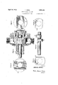
- Fig. 1 is a sectional View longitudinally of the machine, excepting the shaft which is shown in elevation.
- Fig. 2 is an end elevation with the end plate orcover removed.
- Fig. 3 is a vertical section of the machine on line-33 of Fig. 1
- Fig. 4 is a similar sectional view on line 44 of Fig. 1.
- Fig. 5 is a sectional view horizontally through the casing, and showin the working parts therein in elevation.
- Figs. 6 and 7 are end elevations of the cylinder or rotor
- Fig. 8 is a perspective View of the drive shaft, and Figs. 9 and 10 elevations of the separate pistons.
- Fig. 9 and 10 elevations of the separate pistons.
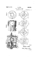
- FIG. 11 is a sectional view of a modified form of machine embodying the invention
- Figs. 12 and 13 are side and end elevations of the rotatable cylinder or rotor.
- Figs. 14 to 17 are diagrammatic views, showing the working parts in different working positions during one revolution of the shaft and onehalf revolution of the rotor.
- the machine comprises a cylindrical body 2 containing a circular chamber 3.
- a cylindrical body 2 containing a circular chamber 3.
- One end of this chamber is closed by an integral wall of the casing, and the opposite end by a removable head or plate 4, or both ends of the casing may be provided with removable heads if desired.
- Separate inlet and outlet 'ports or passages 5 and 6, respectively, are provided within body 2 at opposite sides of circular chamber 3, each port extending circumferentially of the chamber for a substantial distance, say approximately ninety degrees, thereby leaving a closed area of approximately the same are at the top and bottom of the chamber between the two ports.
- a shaft 7 extends through body 2, one end having rotatable bearing within plate 4 where a hollow gland member 8 and packing material is provided to prevent leakage.
- the opposite end of shaft 7 extends through a second gland member 10 fastened by screws or bolts 11 to.body 2, and a drive pulley or gear (not shown) may be fastened to the exposed end of the shaft, or any drive coupling may be used.
- Two circular eccentrics 12-12 form integral parts of shaft 7 where they may revolve in separate orbits side by side within circular chamber 3.
- eccentrics are one-hundred-and-eighty degrees apart, the centers being equally distant from the axis of the shaft, which is ofiset or eccentrically-related to the axis or center of circular chamber 3.
- the degree of offset or eccentricity of shaft 7 to the center of chamber 3 is exactly one-half of the radius of orbital travel of each eccentric 1212.
- the circular orbit of each eccentric 12-12 as defined by the center of the eccentric, touches the axis or center of circular chamber 3. This relationship of parts is essential, otherwise rotatable movement of the rotor member 14, as hereinafter described, cannot occur.
- Rotor member 14 is cylindrical and rotates within chamber 3 with a close fit at its circumference and its opposite ends. The center of its rotative movement is therefore the axis or center of chamber 3. Rotation is imparted to rotor member 14 by both eccentrics 12-42 when power is applied to revolve shaft 7.
- a pair of power translating elements herein also referred to as pistons, 1515 respectively, are rotatably connected or coupled to the eccentrics 12l2.
- each piston has a circular opening therein within which its eccentric fits, the opposite ends of the piston being curved or rounded in the same degree as circular chamber 3, although not necessarily.
- the piston may be either a fiat bar or block, as shown in Figs. 1 to 10, or it may be of cylindrical form as shown in Figs. 11 and 13. Assuming a flat block is employed, the piston embodies two parallel straight sides or edges equally distant from the center of the bushed opening therein.
- Rotor member 14 in that case is formed with two straight-sided channels 1616' extending diametrically across the fiat end faces thereof.
- each eccentric is circular and can only revolve within the circula opening in the piston with which it is coupled, and that no slot is used in the piston to permit other play or movement between the eccentric and the piston.
- each piston operates within its working chamber in the same way as a reciprocating piston opposite a. fixed abutment, that is to say, the piston is oscillated or reciprocated in respect to the circular wall of the casing.
- the revoluble shaft and its eccentrics produce such oscillatory movement of the pistons.
- the pistons are carried around by the rotor in an'orbit eccentric to the circular wall of the casing. The operation is smooth and silent, and the machine may be rotated at a high speed with a minimum application of power. Its construction also lends itself to quantity production at a low cost.
- Figs. 1l-to 13 I show a modified form of machine, in which like parts are designated by the same characters used in Figs. 1 to 10, inasmuch as the working parts are related and operate in the same way, and differ only in shape or form.
- the casing is of greater length
- the rotor member is an elongated cylindrical body instead of a flat disk.
- This cylinder is not channeled at its ends but is formed instead with a pair of circular openings or chambers 1818 spaced apart and extending at right angles diametrically through the body.
- the two pistons 1919 are round or circular in cross section instead of flat, to permit sealing or packing rings 20 to be em ployed as commonly in reciprocable pistons.
- the rotor member 14 of the rotory machine or pump previously described is provided with an axial opening or passage 14:, of a size to permit passing shaft 7 and its eccen-- trics 1212 therethrough in assembling the machine.
- This passage connects chambers 18-18 with each other and therefore the compressed liquid in one chamber would pass into the other chamber through passage 14, with consequent loss of suction or pressure, unless communication between said chambers is shut off.
- the axial opening will be efiectually shut off when the relative diameters of the rotor member and the eccentrics are such as will permit the use of pistons of sufficient length to continuously cover the axial opening throughout their full stroke, while keeping the capacity of the pump within practicable limits.
- a rotary machine or pump including a casing, a circular chamber within said casinghaving inlet andoutlet ports at opposite sides thereof, a cylinder rotatably confined within said chamber having an axialopening, a pair of working chambers extending at right angles to each other, diametrically through sai cylinder and at opposite sides of said opening thereof, pistons, within said working chambers having circular openings therein, and a revoluble shaft having a pair of diametrically related integral eccentrics operating within said piston openings, said shaft being eccentrically mounted with respect to the axis of said circular chamber; and the respective diameters of said eccentrics, piston openings and axial cylinder opening being substantially equal and the diameters of said rotatable cylinder and said eccentrics being limited to dimensions in WhlChthe axial opening of said rotatable cylinder is covered by each of said reciprocating pistons throughout its full stroke.
- a rotary machine or pump including a casing having a circular chamber and inlet and outlet ports, a cylinder rotatably confined within said chamber having an axial opening and also a pair of working chambers extending diametrically at right angles to each other opposite said parts, fiat pistons slidably confined within said working chambers having circular openings therein of substantially the same diameter as said axial opening, and a revoluble shaft having a pair of diametrically-related integral eccentrics operating within said piston openings, said shaft being journaled in ofl'set relation to the axis of said rotatable cylinder 'a distance equal to the radius of orbital travel of said eccentrics, and the respective diameters of said eccentrics, piston openings and axial cylinder opening being substantially equal and the diameters of said rotatable cylinder and said eccentrics being such that said axial Opening is covered by each of said reciprocating pistons throughout its full stroke.
- a rotary pump comprising a casing having a circular chamber and inlet and outlet ports on opposite sides of said chamber;
Description
D. APPEL April 12, 1932.
ROTARY MACHINE OR PUMP s Sheets-Sheet 1 Filed March 19, 1929 April 12, D. APPEL ROTARY MACHINE 0R PUMP Filed March 19f 1929 3 Sheets-Sheet 2 INVENTOR paw/1. flPFEL ATTORN EY April 12, 1932. DAPP L 1,853,394
ROTARY MACHINE OR PUMP Filed March 19, 1929 v 3 Sheets-Sheet 3 INVENTOR rmwez fi pn.
ATTORN EY Patented Apr. 12, 1932 UNITED STATES- DANIEL APPEL,.OF EAST CLEVELAND, OHIO, ASSIGNOR T0 LE ROY A. WESTMAN AND PATENT OFFICE GLENN B. CARMAN, BOTH OF CLEVELAND, OHIO ROTARY MACHINE OR PUMP Application filed March 19, 1929. Serial No. 348,325.
My invention relates to rotary machines, and in general my aim is to provide an exceptionally efficient rotary machine for raising, transferring or compressing liquids or gases. In this machine I employ a plural number of pistons mounted within a single rotatable cylinder or rotor, together with a revoluble shaft having a plural number of eccentrics rotatably coupled to the pistons. All these elements revolve together within a casing or chamber, substantially as hereinafter shown and described, to produce a balanced smoothly-acting aggroupment of working parts adapted to pump or compress liquids or fluids. The pistons maybe either flat or cylindrical in form, and the working chambers in the cylinder or rotor constructed accordingly. The cylindrical form of piston is preferred in a compressor, to permit'piston rings to be employed as commonly in reciprocable engines and pumps. However, the machine will function satisfactorily with flat pistons for certain classes of work.
Now, referring to the drawings, Fig. 1 is a sectional View longitudinally of the machine, excepting the shaft which is shown in elevation. Fig. 2 is an end elevation with the end plate orcover removed. Fig. 3 is a vertical section of the machine on line-33 of Fig. 1, and Fig. 4 is a similar sectional view on line 44 of Fig. 1. Fig. 5 is a sectional view horizontally through the casing, and showin the working parts therein in elevation. Figs. 6 and 7 are end elevations of the cylinder or rotor, and Fig. 8 is a perspective View of the drive shaft, and Figs. 9 and 10 elevations of the separate pistons. Fig. 11 is a sectional view of a modified form of machine embodying the invention, and Figs. 12 and 13 are side and end elevations of the rotatable cylinder or rotor. Figs. 14 to 17 are diagrammatic views, showing the working parts in different working positions during one revolution of the shaft and onehalf revolution of the rotor.
As delineated in Figs. 1 to 10, the machine comprises a cylindrical body 2 containing a circular chamber 3. One end of this chamber is closed by an integral wall of the casing, and the opposite end by a removable head or plate 4, or both ends of the casing may be provided with removable heads if desired. Separate inlet and outlet 'ports or passages 5 and 6, respectively, are provided within body 2 at opposite sides of circular chamber 3, each port extending circumferentially of the chamber for a substantial distance, say approximately ninety degrees, thereby leaving a closed area of approximately the same are at the top and bottom of the chamber between the two ports. A shaft 7 extends through body 2, one end having rotatable bearing within plate 4 where a hollow gland member 8 and packing material is provided to prevent leakage. Gland member Sis filled with a lubricant, and a certain degree of suction is produced in this machine which feeds the lubricant to the working parts through suitable ducts or passages 9 in the shaft.- The opposite end of shaft 7 extends through a second gland member 10 fastened by screws or bolts 11 to.body 2, and a drive pulley or gear (not shown) may be fastened to the exposed end of the shaft, or any drive coupling may be used. Two circular eccentrics 12-12 form integral parts of shaft 7 where they may revolve in separate orbits side by side within circular chamber 3. These eccentrics are one-hundred-and-eighty degrees apart, the centers being equally distant from the axis of the shaft, which is ofiset or eccentrically-related to the axis or center of circular chamber 3. The degree of offset or eccentricity of shaft 7 to the center of chamber 3 is exactly one-half of the radius of orbital travel of each eccentric 1212. As a result the circular orbit of each eccentric 12-12 as defined by the center of the eccentric, touches the axis or center of circular chamber 3. This relationship of parts is essential, otherwise rotatable movement of the rotor member 14, as hereinafter described, cannot occur.
A pair of power translating elements, herein also referred to as pistons, 1515 respectively, are rotatably connected or coupled to the eccentrics 12l2. Thus, each piston has a circular opening therein within which its eccentric fits, the opposite ends of the piston being curved or rounded in the same degree as circular chamber 3, although not necessarily. The piston may be either a fiat bar or block, as shown in Figs. 1 to 10, or it may be of cylindrical form as shown in Figs. 11 and 13. Assuming a flat block is employed, the piston embodies two parallel straight sides or edges equally distant from the center of the bushed opening therein. Rotor member 14 in that case is formed with two straight-sided channels 1616' extending diametrically across the fiat end faces thereof. When two channels are used, as delineated in Figs. 1 to 7, they lie at right angles, or in other words, are quartered in respect to the circle. In these views the piston 15 within channel 16 is shown at the middle of its stroke, and the piston 15 within channel 16 is at one end of its stroke. Also, the two eccentrics 12-12 are centered in the same vertical plane as the center of rotatable member 14, and in that relationship of parts take note that the center of circular eccentric 12 is co-incident with the center or axis of rotor member 14:. This is a dead center position for that piston and rotor member 14, wherefore in the absence of a second eccentric differently positioned, a binding or looking action would take place, thereby either preventing or interfering with the free rotation or rotor member 14. In connection with the foregoing also observe that each eccentric is circular and can only revolve within the circula opening in the piston with which it is coupled, and that no slot is used in the piston to permit other play or movement between the eccentric and the piston.
In operation, when shaft 7 is rotated the two eccentrics 12-12 co-act with the two pistons 1515' to revolve rotor member 14. Two revolutions of the shaft are required to produce one revolution of the rotor member. The pistons are carried around with the rotor member and are moved back and forth within their respective channels or working chambers by the eccentrics, each single revolution of the rotor member producing a forward stroke and a return stroke of the pistons. Each piston is double-acting, that is, its opposite ends function to draw in a charge and to expel a charge at the same time, and
. as two pistons are used at right angles within a single rotor member, the pumping operations of the two pistons overlap and a continuous flow or compression of fluid takes place. Although a rotary machine, each piston operates within its working chamber in the same way as a reciprocating piston opposite a. fixed abutment, that is to say, the piston is oscillated or reciprocated in respect to the circular wall of the casing. The revoluble shaft and its eccentrics produce such oscillatory movement of the pistons. In addition the pistons are carried around by the rotor in an'orbit eccentric to the circular wall of the casing. The operation is smooth and silent, and the machine may be rotated at a high speed with a minimum application of power. Its construction also lends itself to quantity production at a low cost.
In Figs. 1l-to 13, I show a modified form of machine, in which like parts are designated by the same characters used in Figs. 1 to 10, inasmuch as the working parts are related and operate in the same way, and differ only in shape or form. Thus, the casing is of greater length, and the rotor member is an elongated cylindrical body instead of a flat disk. This cylinder is not channeled at its ends but is formed instead with a pair of circular openings or chambers 1818 spaced apart and extending at right angles diametrically through the body. Accordingly. the two pistons 1919 are round or circular in cross section instead of flat, to permit sealing or packing rings 20 to be em ployed as commonly in reciprocable pistons. The rotor member 14 of the rotory machine or pump previously described is provided with an axial opening or passage 14:, of a size to permit passing shaft 7 and its eccen-- trics 1212 therethrough in assembling the machine. This passage connects chambers 18-18 with each other and therefore the compressed liquid in one chamber would pass into the other chamber through passage 14, with consequent loss of suction or pressure, unless communication between said chambers is shut off. Applicant has found that the axial opening will be efiectually shut off when the relative diameters of the rotor member and the eccentrics are such as will permit the use of pistons of sufficient length to continuously cover the axial opening throughout their full stroke, while keeping the capacity of the pump within practicable limits. Obviously, the dimensions of the machine may also be changed and more than two pistons'employed in a single rotor member by merely extending the length of the cylindrical casing and rotor member, and duplicating the parts. Roller or ball bearing may be used, and other modifications can be made without departing materially from the inventive concept. Therefore, I do not wish to be limited to the exact details of construction shown and described herein, but desire the claims to be construed as broadly as the invention and prior art permits. In
that connection, attention is directed to my co-pending applications for improvements in rotary machines, Serial Numbers 348,326 and 348,327, respectively, filed concurrently herewith.
What I claim, is: 1. A rotary machine or pump, including a casing, a circular chamber within said casinghaving inlet andoutlet ports at opposite sides thereof, a cylinder rotatably confined within said chamber having an axialopening, a pair of working chambers extending at right angles to each other, diametrically through sai cylinder and at opposite sides of said opening thereof, pistons, within said working chambers having circular openings therein, and a revoluble shaft having a pair of diametrically related integral eccentrics operating within said piston openings, said shaft being eccentrically mounted with respect to the axis of said circular chamber; and the respective diameters of said eccentrics, piston openings and axial cylinder opening being substantially equal and the diameters of said rotatable cylinder and said eccentrics being limited to dimensions in WhlChthe axial opening of said rotatable cylinder is covered by each of said reciprocating pistons throughout its full stroke.
2. A rotary machine or pump, including a casing having a circular chamber and inlet and outlet ports, a cylinder rotatably confined within said chamber having an axial opening and also a pair of working chambers extending diametrically at right angles to each other opposite said parts, fiat pistons slidably confined within said working chambers having circular openings therein of substantially the same diameter as said axial opening, and a revoluble shaft having a pair of diametrically-related integral eccentrics operating within said piston openings, said shaft being journaled in ofl'set relation to the axis of said rotatable cylinder 'a distance equal to the radius of orbital travel of said eccentrics, and the respective diameters of said eccentrics, piston openings and axial cylinder opening being substantially equal and the diameters of said rotatable cylinder and said eccentrics being such that said axial Opening is covered by each of said reciprocating pistons throughout its full stroke.
3. A rotary pump, comprising a casing having a circular chamber and inlet and outlet ports on opposite sides of said chamber;
' an integral disk-shaped rotor member supported rotatabl within and by the circular wall of said 0 amber, said rotor member permit their passage through said axial opening in said rotor member and of a thiclmess equal to thecross section of said piston chambers; and a pair of pistons slidably confined within said piston chambers having circular.
having piston chambers extending through v said rotor diametrically at right angles to each other and being formed with an axial opening between said piston chambers; a circular cover afiixed to saidcasing having a journal opening offset in respect to the axis 7 of said casing and closed at its outer end; a drive shaft journaled at "one end in said cover, said shaft having a pair of circular integral eccentrics spaced one hundred and 'eighty degrees apart, each of a. diameter to
Priority Applications (1)
| Application Number | Priority Date | Filing Date | Title |
|---|---|---|---|
| US348325A US1853394A (en) | 1929-03-19 | 1929-03-19 | Rotary machine or pump |
Applications Claiming Priority (1)
| Application Number | Priority Date | Filing Date | Title |
|---|---|---|---|
| US348325A US1853394A (en) | 1929-03-19 | 1929-03-19 | Rotary machine or pump |
Publications (1)
| Publication Number | Publication Date |
|---|---|
| US1853394A true US1853394A (en) | 1932-04-12 |
Family
ID=23367510
Family Applications (1)
| Application Number | Title | Priority Date | Filing Date |
|---|---|---|---|
| US348325A Expired - Lifetime US1853394A (en) | 1929-03-19 | 1929-03-19 | Rotary machine or pump |
Country Status (1)
| Country | Link |
|---|---|
| US (1) | US1853394A (en) |
Cited By (8)
| Publication number | Priority date | Publication date | Assignee | Title |
|---|---|---|---|---|
| US2703675A (en) * | 1950-12-14 | 1955-03-08 | James P Johnson | Rotary pump |
| US4649801A (en) * | 1985-04-08 | 1987-03-17 | Johnson Neil M | Compound displacement mechanism for simplified motors and compressors |
| US6206661B1 (en) * | 1998-07-08 | 2001-03-27 | Matsushita Electric Industrial Co., Ltd. | Hermetic compressor |
| US6672848B2 (en) * | 2002-03-19 | 2004-01-06 | Gene-Huang Yang | Cruciform pump |
| US20090238708A1 (en) * | 2004-12-11 | 2009-09-24 | Jin-Gieong Go | Rotary pump |
| WO2009140974A2 (en) * | 2008-05-06 | 2009-11-26 | Juhan Aas | Twin rotary engine |
| US20150098841A1 (en) * | 2013-10-09 | 2015-04-09 | Chart Inc. | Spin Pump With Spun-Epicyclic Geometry |
| WO2021025628A1 (en) * | 2019-08-02 | 2021-02-11 | Up-Steel, S.R.O. | Rotary piston pump, compressor or vacuum pump |
-
1929
- 1929-03-19 US US348325A patent/US1853394A/en not_active Expired - Lifetime
Cited By (14)
| Publication number | Priority date | Publication date | Assignee | Title |
|---|---|---|---|---|
| US2703675A (en) * | 1950-12-14 | 1955-03-08 | James P Johnson | Rotary pump |
| US4649801A (en) * | 1985-04-08 | 1987-03-17 | Johnson Neil M | Compound displacement mechanism for simplified motors and compressors |
| US6206661B1 (en) * | 1998-07-08 | 2001-03-27 | Matsushita Electric Industrial Co., Ltd. | Hermetic compressor |
| US6672848B2 (en) * | 2002-03-19 | 2004-01-06 | Gene-Huang Yang | Cruciform pump |
| US20090238708A1 (en) * | 2004-12-11 | 2009-09-24 | Jin-Gieong Go | Rotary pump |
| US7753664B2 (en) * | 2004-12-11 | 2010-07-13 | Himtool Co., Ltd. | Rotary pump |
| WO2009140974A3 (en) * | 2008-05-06 | 2010-03-18 | Juhan Aas | Twin rotary engine |
| WO2009140974A2 (en) * | 2008-05-06 | 2009-11-26 | Juhan Aas | Twin rotary engine |
| US20150098841A1 (en) * | 2013-10-09 | 2015-04-09 | Chart Inc. | Spin Pump With Spun-Epicyclic Geometry |
| CN105765220A (en) * | 2013-10-09 | 2016-07-13 | 查特股份有限公司 | Spin pump with spun-epicyclic geometry |
| US9771931B2 (en) * | 2013-10-09 | 2017-09-26 | Chart Inc. | Spin pump with spun-epicyclic geometry |
| US20180073493A1 (en) * | 2013-10-09 | 2018-03-15 | Chart Inc. | Spin pump with spun-epicyclic geometry |
| US10465669B2 (en) * | 2013-10-09 | 2019-11-05 | Chart Inc. | Spin pump with spun-epicyclic geometry having piston bores capped with caps including ducts or valves within the rotor |
| WO2021025628A1 (en) * | 2019-08-02 | 2021-02-11 | Up-Steel, S.R.O. | Rotary piston pump, compressor or vacuum pump |
Similar Documents
| Publication | Publication Date | Title |
|---|---|---|
| US6659744B1 (en) | Rotary two axis expansible chamber pump with pivotal link | |
| US7670121B2 (en) | Spherical fluid machines | |
| US4844708A (en) | Elliptical-drive oscillating compressor and pump | |
| US1853394A (en) | Rotary machine or pump | |
| US1989552A (en) | Rotary compressor | |
| US1910876A (en) | Rotary pump | |
| US1967167A (en) | Fluid compression apparatus | |
| US2015307A (en) | Rotary pump, compressor, or driven motor | |
| US2089593A (en) | Rotary compressor and the like | |
| US2248452A (en) | Rotary pump | |
| US1837714A (en) | Rotary pump | |
| US2413636A (en) | Compressor unit | |
| US3037488A (en) | Rotary hydraulic motor | |
| WO2023280183A1 (en) | Cavity-dividing rotor volume mechanism | |
| US2336344A (en) | Rotary pump | |
| US2628014A (en) | Multiple stage nonslip vacuum pump | |
| US1945220A (en) | Rotary pump machine | |
| US1459637A (en) | Rotary machine | |
| US3331326A (en) | Rotary pump | |
| US2513447A (en) | Rotary pump or motor | |
| US1983034A (en) | Rotary pump, compressor, engine, and the like | |
| US1427740A (en) | Pump | |
| US2103474A (en) | Reversible planetary piston pump | |
| US2360833A (en) | Rotary pump | |
| US2260867A (en) | Pump |