US1853366A - Button sewing machine - Google Patents
Button sewing machine Download PDFInfo
- Publication number
- US1853366A US1853366A US398408A US39840829A US1853366A US 1853366 A US1853366 A US 1853366A US 398408 A US398408 A US 398408A US 39840829 A US39840829 A US 39840829A US 1853366 A US1853366 A US 1853366A
- Authority
- US
- United States
- Prior art keywords
- work
- button
- thread
- knife
- sewing
- Prior art date
- Legal status (The legal status is an assumption and is not a legal conclusion. Google has not performed a legal analysis and makes no representation as to the accuracy of the status listed.)
- Expired - Lifetime
Links
Images


Classifications
-
- D—TEXTILES; PAPER
- D05—SEWING; EMBROIDERING; TUFTING
- D05B—SEWING
- D05B3/00—Sewing apparatus or machines with mechanism for lateral movement of the needle or the work or both for making ornamental pattern seams, for sewing buttonholes, for reinforcing openings, or for fastening articles, e.g. buttons, by sewing
- D05B3/12—Sewing apparatus or machines with mechanism for lateral movement of the needle or the work or both for making ornamental pattern seams, for sewing buttonholes, for reinforcing openings, or for fastening articles, e.g. buttons, by sewing for fastening articles by sewing
- D05B3/14—Sewing apparatus or machines with mechanism for lateral movement of the needle or the work or both for making ornamental pattern seams, for sewing buttonholes, for reinforcing openings, or for fastening articles, e.g. buttons, by sewing for fastening articles by sewing perforated or press buttons
-
- D—TEXTILES; PAPER
- D05—SEWING; EMBROIDERING; TUFTING
- D05B—SEWING
- D05B65/00—Devices for severing the needle or lower thread
-
- D—TEXTILES; PAPER
- D05—SEWING; EMBROIDERING; TUFTING
- D05B—SEWING
- D05B73/00—Casings
- D05B73/04—Lower casings
- D05B73/12—Slides; Needle plates
Definitions
- means are provided for cutting the thread at the proper point after the stitchingr cycle and before the work is removed. This may be accomplished automatically-when the button clamp is raised to release the work.
- the machine stops at the end of theV stitchingcycle the needle is retracted, the thread passing therefrom through a stitching hole in the button and the work, being looped about the looping ymechanism and eX- tiiding to the knot.
- a knife - is arranged to cut the loop portion of the thread between the looper and the work, approaching the thread from the outside of the loop and cutting the thread between the looper and the knot.
- Figure 2 is a yfragmentary perspective of cooperating portions of the cutter vactuating mechanism
- Figure 3 is a horizontalsection through the machine substantially online 3 3 of Figure 1.
- Figure 4 is a view similar to a vportionfof Figure 3, but showingparts of the Vbuttoni clamp broken away to disclose ⁇ the thread cutter.
- Figure 5 is a fragmentaryplan, partsbeing broken away showing a modified form of cutter actuatingmechanism in knife-projected
- Figures 6 and 7 areviews similar to Figure t, but showing the knife in projected position, Figure 7-showing a ymodied construeu tion. Y
- y l y F igure10 is a planl ,of a back face of the wodrk showing the position of the cut thread en s.
- themachineL illustrated includes a worktable 1 supporting a cloth :plate on which the work is supported and which is held Aagainst the upper face of the work table by a superposed button clamp of any suitable type indicated vat 2.
- This button clamp as shown is carried by an arm 3 pivotedl rearwardly ofthe button clamp in the usual manner and arranged to beliftedffroin the cloth plate to release the work by any suitable mechanism which com- Vinonly is actuatedibya treadle.
- this raising mechanism yincludes a rock shaft arrange'd horizontally along actuating mechanismY and which also has iXed thereto an arm 10 carrying tlieupper endfof ka chain ,11, thelofwer end of which is IiXed as at 12 to a portion of the button clam Th-e button clamp. andthe cloth plate may e vibratedlaterally to bring eacho'f azpapirvofv holes in the button into the needle path alternately during the stitching cycle, in a manner well known, a rocking segment 16 and connecting link 17 being shown for that purpose.
- the sewing armG is provided with the usual head 18 in which is carried a needle bar 13.
- this needle bar is provided with a pair of sewing needles 14, this machine having a pair of sewing needles being more particularly illustrated, described and claimed in my application for patent Serial No. 351,391, filed March 30, 1929. While the two-needle machine is herein shown, it is of course evident that the invention might be applied to a single-needle machinek though the utility of this invention is more clearly apparent in the two-needle machine where it is necessary to sever two threads in order to free the work from the machine at the end of the stitching cycle.V
- each one of these needles has its own sewing lthread and places stitches through a pair ofV holes in the button and through the work, the stitching being done simultaneously with the two needles.
- this looper mechanism comprises a latch needle as shown at 2O in Figure 8, this latch needle being arranged to take loops of thread from boththe needles 14 and'to draw these loops through loops previously drawn to produce the chain stitches. 1t will be noted that whenever the stitching needle is retracted from the work a loop of thread extends therefrom about the looper mechanism and back to the work and in order to remove the work at the end of the stitching cycle it is necessary to sever the thread in order that the work may be released.
- this thread-severing mechanism comprises a knife as 30 having a V shaped cutting edge 31 at its forward end, this knife being positioned on the upper face of the work table and beneath the cloth plate 15 and the button clamp and as illustrated it is arranged to be brought into action at the end of the stitching cycle, and preferably, and as shown, it is actuated by the button clamp raising mechanism to sever the stitching thread or threads.
- This knife 30 is shown as secured to an actuating bar 36 as by means of a pair of screws 32 and 33.
- Atleast one ofthese screws is shown as extending through a slotv 34 in the knife in order that the angular position of the knife may be adjusted as desired in order to bring the desired cutting portion Athereof into proper position relative tothe throat 35 in the work table through which the needles pass.
- bar 36 is provided with a pair of guide slots 37 and 38 through which extend guide screws 39 and 40, respectively, the bar 36 being held thereby at one side of the cloth plate 15, the forward end of the knife being laterally oset to extend beneath the cloth plate.
- the slot 37 is of sufhcient width to permit the bar 36 to slide easilyon the screw 39 but the rear end portion of the slot' ⁇ 38 is shown as wider: than the forward portion so as to permit a lateral swinging motion of the bar 36 about the screw 39 ⁇ as an axis.
- the bar 36 is shown as moved axially and laterally by means of a lever 42 pivoted at 43 on the top of the work table.
- the inner end of the lever 42 is provided with a slot 44 in which rides a pin 45 projecting from the bar 36 and the parts are so proportioned that when the lever 42 is swung to project the knife carrier bar 3G forwardly, this pin 45 sgrikesthe outer end of the slot.
- the lever 42 is normally held in retracted position with the knife retracted from the throat 35, as shown in Figure 3, as by means of a spring 55, one end of which engagesan abutment such as a screw 56 fixed to the machine frame and the other end of which en gages the lever 42 as at 57.
- the outer end 'of the lever 42 is shownas provided with spaced jaws 60 between which is mounted a cam roller 61 and fixed to 'the pull rod 8 of 'the button clamp raising mechanism is a cam plate 65 haring a cam edge 66, which, when the rod 8 is depressed, impin'ges on the fcllower roll 61 and swings the outer end of the lever 42 rea'rwardlythus to push the knife forwardly as shown in Figure 6 yto cut the threads.
- the lever 42 is also shown as provided with a cut away portion 67 in which'the rod 8 rides.
- the cam plate 65 is carried by a collar 70 adjustable on the rod 8 and the rod 8 also carries a collar 7l to which is attached the upper end of the pull chain 72 which leads to the actuating treadle mechanism.
- the thread cutter is projected forwardly to sever the thread so that the work may be freely removed from the machine.
- Adjustment of the position of the cam plate 65 on the rod' determines the closeness of the cutting of the threads to the work and thus the length of the thread ends er;v tending therefrom. The lower the cam plate is set, the earlier is the cutting effected on raising the button clamp and the closer are the cuts to the work and the shorter the threadends.
- the knife may be guided for a -fre'nt and back motion without thelateral motionfif desired.
- the guide slots for 'the bar B6 are both ef substantially the width of the guide pins or 'screws 39 and 40 andthe slot 44 in the lever 42 to receive the, pinV 45 is sufciently long lso that its end'sl'clear the pin in all positions las'. is illustrated in Figure 7.
- the knifev may be adjusted lso that the cutting lportion at either side'ofits apex may be b-rought into operative relation to the thread loops.
- the knifemaybe adjusted 'as it ⁇ becomes dull in one portion to bring another portion of the cutting edge ⁇ into operative position by merely adjusting the angular relation of the'knife toits actuating bar 36, his being facilitated by its screw andsloticonnection thereto.
- a button sewing machine having a work table means above said tablefor 4sup-'porting work and a button in position for sewing the.v
- a button sewing machine having means for supporting work and a button in 'position for sewing the button to the work, sewing instrumentalities including a pair of needles for simultaneously placing securing stitches through holes in the button and throughv the work, and means actuable at the end of a stitchingcycle to ⁇ out the thread from each Vneedle adjacent tok the work.
- a button sewing machine having means for sup-porting workand a button in position for securing of the button to the work, chain vstitch sewing ⁇ instrumentalities including a latch needlefor engaging vsuccessive loops of thread ⁇ and drawing them through the previ- ⁇ ously formed loops,l a cutter,v and means yactuable at theend of a'stitching cycle forv bringing said cutter against a loop of thread held ktaut by said latch needle to sever the thread to facilitate removal of the work from the machine.
- Albritton sewing machine having avwork flee ' table means above said table for supporting workanda button in position for sewing the button to the work, means for sewing the button to the work including means for drawing successive loops of thread, and means actuable at the end of the stitching cycle and while a loop of thread isiheld by said drawing means for severing the thread between Vsaid Vtable and supporting means at said loop to facilitate removal of the work from the machine.
- avwork flee ' table means above said table for supporting workanda button in position for sewing the button to the work, means for sewing the button to the work including means for drawing successive loops of thread, and means actuable at the end of the stitching cycle and while a loop of thread isiheld by said drawing means for severing the thread between Vsaid Vtable and supporting means at said loop to facilitate removal of the work from the machine.
- a button sewing machine having means for supporting a button and work in position to stitch the button to the work, sewing instrumentalities including a plurality of needles each having a sewing thread vand a looper for taking loops of thread from both needles, and means actuable at the end of the stitching cycle to sever the threads between the work and the looper.
- a button sewing machine having means for supporting a button and work in position tostitch the button to the work, sewing instrumentalities including a plurality ⁇ of needles each having a sewing thread and means for taking loops of thread from said needles, and means actuable to cut the loops of all the threads; f
- a button sewing machine having means for supporting a button and work in position to stitch the button to the work, sewing instrumentalities including a plurality of needles each having a sewing thread and means for taking loops of thread from said needles, a knife andmeans actuable to bring said knife against all the threads at the loops and sever said threads.
- a but- ⁇ ton clamp for holding a button and work in position to sew the button to the work, means for lifting the button clamp, and sewing instrumentalities including a looper for fixing the button to the work by loops of thread in chain stitchformation, aknife mounted for movement above the work table and beneath the button clamp, and means actuated by the lifting of the button clamp to move the knife against a loop of thread held by the looper md to sever the thread on one side of said oop.
- a vmachine of the class described having a work table, a cloth plate on said work table, means for holding a button and work in'superposed relation above said cloth plate in position to vfix the button to the work, and sewing instrumen- -talities including. mechanism positioned be- 'neather the work table for sewing the button to the work by chain stitches, a thread cutter positioned between the work table andthe cloth plate, and means for actuating said cutter to cut' thread extending from thework to said mechanism.
- a button clamp for holding a button Vand work above said table in position to fix the button to the work, means including a depressible element for raising such button clamp to release the work, and sewing instrumentalities to stitch the button to the work while the clamp is down, a knife slidably guided on the work table, a lever operatively connected to said knife to project and retract said knife by swinging of said lever, means yieldingly holding said knife retracted, a cam carried by said depressible element, and a cam follower carried by said lever in the path of said cam when said knife is retracted, said caml being shaped to swing said lever and project said knife to cut the stitching thread between the work and certain of said instrumentalities when the button .clamp is being raised.
- a button clamp for holding a button and work above said table in position to fix the button to the work, means including a depressible element for raising such button clamp to release the work, and sewing instrumentalities to stitch the button to the work while ⁇ the clamp is down, a knife slidably guided on the work table, a lever operatively connected to said knife to project and retract said knife by swinging of said lever, means yieldingly holding said knife retracted, a cam carried by said depressible element, and a cam follower carried by said lever in the path of said cam when said knife is retracted, said cam being shaped to swing said lever and project said knife to cut the stitching thread between the work and certain of said instrumentalities when the button clamp is being raised, said cam being adjustable relative to said depressible element to adjust the time of cutting rela-tive to the raising of said button clamp to thereby determine the length of the cut thread end.
Description
April l2, 1932. R. LYoNs BUTTON SEWING MACHINE 3 sheets-sheet Filed om.v 9, 1929 April l2, 193.2. R. L. I YoNs BUTTON SEWING MACHINE Filed Oct. 9, 1929 .'5 Sheets-Sheet 2 April l2,- 1932. R. L. LYONS A- BUTTON SEWING MACHINE Filed oct. 9, 1929 3 sheets-sheet 5 oewl ' Lig/32" J:
Patented pr. 1.2, 19.32.i
UNTD i STATES PATENT ori-ici:
ROBERT L. LYoNs, or WALTHAM, MAssAcH-usETTs BUTTON SEWING MACHINE Application led ctober 9, 1929. Seria1'No.'398,408.
chine disclosed and Vclaimed in my application for patent Serial No. 351,391, iiled March 30, 1929, for 'fasteningmeans and method and machine for securing buttons to work therewith, no special knotting stitch is necessary, the two threads being effectually knottedat each stitch. The threads may then be broken at the end of the stitchingcycle as in the case of the single-needle machine adj acent to the knot at the last stitch. This breaking of the thread, particularly when heavy thread is employed, is not always easy and sometimes the thread does not break at the desired place relative to the knot, either leaving a long threadend or being so close to endangerthe security ofthe knot.
In accordance with the present invention, therefore, means are provided for cutting the thread at the proper point after the stitchingr cycle and before the work is removed. This may be accomplished automatically-when the button clamp is raised to release the work.
lVhen the machine stops at the end of theV stitchingcycle the needle is retracted, the thread passing therefrom through a stitching hole in the button and the work, being looped about the looping ymechanism and eX- tiiding to the knot. In accordance with this invention a knife -is arranged to cut the loop portion of the thread between the looper and the work, approaching the thread from the outside of the loop and cutting the thread between the looper and the knot.
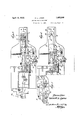
For a more complete understanding offthis invention, reference may be had tothe accompanying drawings in which Figure l-is a-,fragmentary side elevation of a button sewing machine provided with a l thread cutter. A.
,Figure 2 is a yfragmentary perspective of cooperating portions of the cutter vactuating mechanism;
Figure 3 is a horizontalsection through the machine substantially online 3 3 of Figure 1.
Figure 4 is a view similar to a vportionfof Figure 3, but showingparts of the Vbuttoni clamp broken away to disclose` the thread cutter.
Figure 5 is a fragmentaryplan, partsbeing broken away showing a modified form of cutter actuatingmechanism in knife-projected,
position.; A
Figures 6 and 7 areviews similar to Figure t, but showing the knife in projected position, Figure 7-showing a ymodied construeu tion. Y
lFigures Sand 9 are fragmentary perspec- -tivesillustrating successive positions of certain ofthevmacliine parts with relationto the work. y l y F igure10 is a planl ,of a back face of the wodrk showing the position of the cut thread en s.
Referring rst to Figures 1 and 3, themachineL illustrated includes a worktable 1 supporting a cloth :plate on which the work is supported and which is held Aagainst the upper face of the work table by a superposed button clamp of any suitable type indicated vat 2. This button clamp as shown is carried by an arm 3 pivotedl rearwardly ofthe button clamp in the usual manner and arranged to beliftedffroin the cloth plate to release the work by any suitable mechanism which com- Vinonly is actuatedibya treadle. As illustrated Qin yFigure A1 Vthis raising mechanism yincludes a rock shaft arrange'd horizontally along actuating mechanismY and which also has iXed thereto an arm 10 carrying tlieupper endfof ka chain ,11, thelofwer end of which is IiXed as at 12 to a portion of the button clam Th-e button clamp. andthe cloth plate may e vibratedlaterally to bring eacho'f azpapirvofv holes in the button into the needle path alternately during the stitching cycle, in a manner well known, a rocking segment 16 and connecting link 17 being shown for that purpose. The sewing armG is provided with the usual head 18 in which is carried a needle bar 13. As illustrated in Figure 1 this needle bar is provided with a pair of sewing needles 14, this machine having a pair of sewing needles being more particularly illustrated, described and claimed in my application for patent Serial No. 351,391, filed March 30, 1929. While the two-needle machine is herein shown, it is of course evident that the invention might be applied to a single-needle machinek though the utility of this invention is more clearly apparent in the two-needle machine where it is necessary to sever two threads in order to free the work from the machine at the end of the stitching cycle.V
As illustrated in my prior application for patent and as shown also in Figures 8 and 9, each one of these needles has its own sewing lthread and places stitches through a pair ofV holes in the button and through the work, the stitching being done simultaneously with the two needles. In button s-ewing machin-es of the chain stitch type Vthe loops of threadV passed through the button are taken successively by some form of looper mechanism beneath the work table, each loop as taken being passed through a previously formed loop in ord-er to form the chain stitches.A
' ln the two-thread machine of the chain stitch type as illustrated in my prior appli- KK cation hereinbefore referred to, this looper mechanism comprises a latch needle as shown at 2O in Figure 8, this latch needle being arranged to take loops of thread from boththe needles 14 and'to draw these loops through loops previously drawn to produce the chain stitches. 1t will be noted that whenever the stitching needle is retracted from the work a loop of thread extends therefrom about the looper mechanism and back to the work and in order to remove the work at the end of the stitching cycle it is necessary to sever the thread in order that the work may be released.
the looper and being so positioned as to cut Y the thread a short distance from the knot and in the case of the two-needle machine to cut both sewing threads.V 'By this'means sufficient thread extending from the knot is insured to prevent untying of the knot while insuring against the leaving of a long thread end at the work and providing sufficient thread extending from the needle at the end ofthe severing operation to prevent 'likelihood of the needle becoming unthreaded or of there being insufficient length of thread endv for the starting of the next stitching las well asV to move. it forwardly.
cycle. As illustrated in the drawings this thread-severing mechanism comprises a knife as 30 having a V shaped cutting edge 31 at its forward end, this knife being positioned on the upper face of the work table and beneath the cloth plate 15 and the button clamp and as illustrated it is arranged to be brought into action at the end of the stitching cycle, and preferably, and as shown, it is actuated by the button clamp raising mechanism to sever the stitching thread or threads. This knife 30 is shown as secured to an actuating bar 36 as by means of a pair of screws 32 and 33. Atleast one ofthese screws is shown as extending through a slotv 34 in the knife in order that the angular position of the knife may be adjusted as desired in order to bring the desired cutting portion Athereof into proper position relative tothe throat 35 in the work table through which the needles pass.
The lever 42 is normally held in retracted position with the knife retracted from the throat 35, as shown in Figure 3, as by means of a spring 55, one end of which engagesan abutment such as a screw 56 fixed to the machine frame and the other end of which en gages the lever 42 as at 57. The outer end 'of the lever 42 is shownas provided with spaced jaws 60 between which is mounted a cam roller 61 and fixed to 'the pull rod 8 of 'the button clamp raising mechanism is a cam plate 65 haring a cam edge 66, which, when the rod 8 is depressed, impin'ges on the fcllower roll 61 and swings the outer end of the lever 42 rea'rwardlythus to push the knife forwardly as shown in Figure 6 yto cut the threads. The lever 42 is also shown as provided with a cut away portion 67 in which'the rod 8 rides. As illustrated in Figure 2 the cam plate 65 is carried by a collar 70 adjustable on the rod 8 and the rod 8 also carries a collar 7l to which is attached the upper end of the pull chain 72 which leads to the actuating treadle mechanism. Thus as the button clamp is raised at the end of the stitching` cycle to free the work, the thread cutter is projected forwardly to sever the thread so that the work may be freely removed from the machine. Adjustment of the position of the cam plate 65 on the rod'determines the closeness of the cutting of the threads to the work and thus the length of the thread ends er;v tending therefrom. The lower the cam plate is set, the earlier is the cutting effected on raising the button clamp and the closer are the cuts to the work and the shorter the threadends. Y Another means lof producing the lateral as i' well' as thel forwardfmotion of theknife 'is 'interfase ai' Figure' in 'which uit has se is provided with afprojecting 'pin VSOwhich,
and rides :over a shoulder v8 1 on the work table.v While this lateral motion of the knife is 'often desirable, the knife may be guided for a -fre'nt and back motion without thelateral motionfif desired. Wherethis is desired the guide slots for 'the bar B6 are both ef substantially the width of the guide pins or 'screws 39 and 40 andthe slot 44 in the lever 42 to receive the, pinV 45 is sufciently long lso that its end'sl'clear the pin in all positions las'. is illustrated in Figure 7. Particularly where no lateral movement 'of the knife is clesire'd, the knifevmay be adjusted lso that the cutting lportion at either side'ofits apex may be b-rought into operative relation to the thread loops. Thus the knifemaybe adjusted 'as it` becomes dull in one portion to bring another portion of the cutting edge `into operative position by merely adjusting the angular relation of the'knife toits actuating bar 36, his being facilitated by its screw andsloticonnection thereto.
` I Certain embodiments "of this invention having thus been described, itshould be evident to those skilled in the art that various 'changes and modifications might be made therein without departing from its spirit or scope as 'defined by the appended claims.
Iclaim:
1. A button sewing machine having a work table means above said tablefor 4sup-'porting work and a button in position for sewing the.v
2. A button sewing machinehaving means for supporting work and a button in 'position for sewing the button to the work, sewing instrumentalities including a pair of needles for simultaneously placing securing stitches through holes in the button and throughv the work, and means actuable at the end of a stitchingcycle to `out the thread from each Vneedle adjacent tok the work.
3. A button sewing machine having means for sup-porting workand a button in position for securing of the button to the work, chain vstitch sewing` instrumentalities including a latch needlefor engaging vsuccessive loops of thread `and drawing them through the previ- `ously formed loops,l a cutter,v and means yactuable at theend of a'stitching cycle forv bringing said cutter against a loop of thread held ktaut by said latch needle to sever the thread to facilitate removal of the work from the machine.
y 4. Albritton sewing machine having avwork flee ' table means above said table for supporting workanda button in position for sewing the button to the work, means for sewing the button to the work including means for drawing successive loops of thread, and means actuable at the end of the stitching cycle and while a loop of thread isiheld by said drawing means for severing the thread between Vsaid Vtable and supporting means at said loop to facilitate removal of the work from the machine. o 5. A button sewing machine having means for supporting a button and work in position to stitch the button to the work, sewing instrumentalities including a plurality of needles each having a sewing thread vand a looper for taking loops of thread from both needles, and means actuable at the end of the stitching cycle to sever the threads between the work and the looper.
6. A button sewing machine having means for supporting a button and work in position tostitch the button to the work, sewing instrumentalities including a plurality` of needles each having a sewing thread and means for taking loops of thread from said needles, and means actuable to cut the loops of all the threads; f
7. A button sewing machine having means for supporting a button and work in position to stitch the button to the work, sewing instrumentalities including a plurality of needles each having a sewing thread and means for taking loops of thread from said needles, a knife andmeans actuable to bring said knife against all the threads at the loops and sever said threads.
8. In combination with a machine of the class described having a work table, a but-` ton clamp for holding a button and work in position to sew the button to the work, means for lifting the button clamp, and sewing instrumentalities including a looper for fixing the button to the work by loops of thread in chain stitchformation, aknife mounted for movement above the work table and beneath the button clamp, and means actuated by the lifting of the button clamp to move the knife against a loop of thread held by the looper md to sever the thread on one side of said oop.
9.'In combination with a vmachine of the class described having a work table, a cloth plate on said work table, means for holding a button and work in'superposed relation above said cloth plate in position to vfix the button to the work, and sewing instrumen- -talities including. mechanism positioned be- 'neather the work table for sewing the button to the work by chain stitches, a thread cutter positioned between the work table andthe cloth plate, and means for actuating said cutter to cut' thread extending from thework to said mechanism.
10. Incombination with a machine of the class described having a work tablemean`s' for holding a button and vwork in superposed position to fix the button to the work above said table, and sewing instrumentalities for Xing the Vbutton to the work, a member slidably guided on said work table, a knife lcarried by said member, a lever operatively connected to said member, means yieldingly holding said member in position to hold said -knife retracted, and means actuable to rock said lever to proj ect said knife against and to cut a thread held by. said instrumentalities.
11. In combination with a machine of the class described having a work table, means for holding a button and work in position to fix the button to the work above saidtable, and sewing instrumentalities for fixing the button to the work, a member slidably guided on said work table, a knife carried by said member, a lever operatively connected to said member, means yieldingly holding said member in position to hold said knife retracted, and means actuable to rock said lever to project said knife against and to cut a thread held by said instrumentalities, said operative connections including means for causing said knife to be moved in a curved path as it is projected. Y
12. InV combination with a machine of the class described having a work table, means for holding a button and work in position to fix the button to the work above said table, and sewing instrumentalities for fixing the button to the work, a member slidably guided on said work table, a knife carried by said member, alever having a pin and slot connection with said member, vmeans yieldingly holding said member in position to hold said knife retracted, and means actuable to rock said lever to project said knife against and to cut a thread held by said instrumentalities, the pin of said pin and slot connection being positioned to engage one end of said slot as said knife is projected whereby further rocking of said lever projects said knife in a curved path.
13. In combination with a machine of the class described having a work table, a button clamp for holding a button Vand work above said table in position to fix the button to the work, means including a depressible element for raising such button clamp to release the work, and sewing instrumentalities to stitch the button to the work while the clamp is down, a knife slidably guided on the work table, a lever operatively connected to said knife to project and retract said knife by swinging of said lever, means yieldingly holding said knife retracted, a cam carried by said depressible element, and a cam follower carried by said lever in the path of said cam when said knife is retracted, said caml being shaped to swing said lever and project said knife to cut the stitching thread between the work and certain of said instrumentalities when the button .clamp is being raised.
14;. In combination with a machine of the class described having a work table, a button clamp for holding a button and work above said table in position to fix the button to the work, means including a depressible element for raising such button clamp to release the work, and sewing instrumentalities to stitch the button to the work while` the clamp is down, a knife slidably guided on the work table, a lever operatively connected to said knife to project and retract said knife by swinging of said lever, means yieldingly holding said knife retracted, a cam carried by said depressible element, and a cam follower carried by said lever in the path of said cam when said knife is retracted, said cam being shaped to swing said lever and project said knife to cut the stitching thread between the work and certain of said instrumentalities when the button clamp is being raised, said cam being adjustable relative to said depressible element to adjust the time of cutting rela-tive to the raising of said button clamp to thereby determine the length of the cut thread end.
In testimony whereof I have affixed my signature.
ROBERT L. LYON S.
Priority Applications (1)
| Application Number | Priority Date | Filing Date | Title |
|---|---|---|---|
| US398408A US1853366A (en) | 1929-10-09 | 1929-10-09 | Button sewing machine |
Applications Claiming Priority (1)
| Application Number | Priority Date | Filing Date | Title |
|---|---|---|---|
| US398408A US1853366A (en) | 1929-10-09 | 1929-10-09 | Button sewing machine |
Publications (1)
| Publication Number | Publication Date |
|---|---|
| US1853366A true US1853366A (en) | 1932-04-12 |
Family
ID=23575278
Family Applications (1)
| Application Number | Title | Priority Date | Filing Date |
|---|---|---|---|
| US398408A Expired - Lifetime US1853366A (en) | 1929-10-09 | 1929-10-09 | Button sewing machine |
Country Status (1)
| Country | Link |
|---|---|
| US (1) | US1853366A (en) |
-
1929
- 1929-10-09 US US398408A patent/US1853366A/en not_active Expired - Lifetime
Similar Documents
| Publication | Publication Date | Title |
|---|---|---|
| US2341184A (en) | Method of attaching articles | |
| US2889790A (en) | Apparatus for producing piped garment openings | |
| US1853366A (en) | Button sewing machine | |
| US1876538A (en) | althens | |
| US2423001A (en) | Thread cutter for sewing machines | |
| US2324235A (en) | Buttonhole sewing machine | |
| US1787928A (en) | Sewing machine | |
| US1933038A (en) | Fabric trimming and thread laying mechanism for sewing machines | |
| US2354559A (en) | Buttonhole sewing machine | |
| US1988460A (en) | Buttonhole sewing machine | |
| GB658439A (en) | Improved method of, and means for, repetition sewing | |
| US2180424A (en) | Cutting and hemming and stitching apparatus | |
| US1332511A (en) | Sewing-machine | |
| US1463325A (en) | Sewing machine | |
| US1743356A (en) | Thread trimmer for sewing machines | |
| US1319668A (en) | Trimmer for sewing-machines | |
| US1396111A (en) | Buttonhole-sewing machine | |
| US2284514A (en) | Sewing machine | |
| US2250973A (en) | Thread-cutting mechanism for sewing machines | |
| US1865140A (en) | Buttonhole sewing machine | |
| GB510072A (en) | Improvements in or relating to feeding mechanism for sewing machines | |
| US737122A (en) | Thread-cutting mechanism for sewing-machines. | |
| US1646946A (en) | Cord-handling mechanism for buttonhole-sewing machines | |
| US1785412A (en) | Label-sewing machine | |
| US1494097A (en) | Stitching machine |