US1853360A - Automatic circuit control means - Google Patents
Automatic circuit control means Download PDFInfo
- Publication number
- US1853360A US1853360A US491386A US49138630A US1853360A US 1853360 A US1853360 A US 1853360A US 491386 A US491386 A US 491386A US 49138630 A US49138630 A US 49138630A US 1853360 A US1853360 A US 1853360A
- Authority
- US
- United States
- Prior art keywords
- circuit
- switch
- air
- current
- exciter
- Prior art date
- Legal status (The legal status is an assumption and is not a legal conclusion. Google has not performed a legal analysis and makes no representation as to the accuracy of the status listed.)
- Expired - Lifetime
Links
Images
Classifications
-
- H—ELECTRICITY
- H02—GENERATION; CONVERSION OR DISTRIBUTION OF ELECTRIC POWER
- H02P—CONTROL OR REGULATION OF ELECTRIC MOTORS, ELECTRIC GENERATORS OR DYNAMO-ELECTRIC CONVERTERS; CONTROLLING TRANSFORMERS, REACTORS OR CHOKE COILS
- H02P9/00—Arrangements for controlling electric generators for the purpose of obtaining a desired output
Definitions
- My invention relates to means for automatically controlling the circuit of the motors of cars provided with gas-electric internal combustion engines, namely cars provided witha well known type of gas-electric internal combustion engines atpresent employed on certain railroad systems, for generating the current whereby the motors are operated.
- the invention has for its object the pro- 1o vision of means whereby the traction motors will be protected from overload damage during certain operating conditions; that is to say, my invention relates to means which automatically becomes effective so as to prevent the-generator currentbeing applied or admitted to the traction motors while the brakes of the car or train are set.
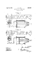
- Figure 1 is a diagrammatic illustration of a circuit provided with 'automatic control means, more or less schematically shown, illustrating the circuit and means in normal operating condition.
- Figure 2 is asimilar view disclosing a second position or condition of the circuit and means.
- My invention is especially intended for use in connection with cars provided with current generating engines and storage batteries for operating the traction motors of the cars.
- This type of engine and the motor are generally known and as these elements form no part of my invention ⁇ specific illustration and detail description thereof need not be entered into; nor is it deemed necessary to make a showing of a traction car of the type "10 in question; it being understood, however.,
- the v diagrammatic illustrations in the drawings involve the usual storage battery indicated at 10 provided with the lead lines 11 and 12 having a well known type of switch indicated at 18 an exciter field contactor coil at 14 provided with the usual core which is magnetizedwhen current flows through the coil.
- the magnetized core attracts the pivoted arm or armature 15 thereby closing the circuit of the exciter shunt ieldl, the generator field exciter indicated at 17 and of the current generator generally indicated at 18.
- the circuit also involves the traction motors indicated at 19 and the usual controller indicated at 20.
- the circuit also involves a switch located at 21, which is controlled by the throttle of the internal combustion engine, bein@I arranged so that when the engine throttle (uot shown) is closed the switch 21 is open and when the engine throttle is manually opened, switch 21 will be closed.
- the circuit also involves an exciter lield resistor generally indicated at 22.
- My improved automatically operated means now to be described are intended to obviate this difficulty and damage by prevent- 1n tragction motors while the brakes are set.
- my 1mproved means is operatively interposed between an air cylinder 23 of the air brake system and a portion of the aforefdescribed circuit and involves an automatic clrcuit controller in the form of a pneumatically operated element consisting of a chamber 24 provided with a cap portion 25 which is bolted to the chamber 24 with a suitable diaphragm 26 therebetween.
- the cap portion 25 is connected by ipe 27 with the air brake line 28 which lea s to the air-brake cylinder 23, which latter is provided with the usual sprino ⁇ controlled iston 29 which in Figure 1 is shown in bra e released position, Y
- the chamber 24 is provided with a plunger 30, one end whereof is secured to diaphragm 26, while the other end extends through the end wall of chamber 24 and is provided with an arm 31.
- the plunger 30, intermediate of the end wall of the chamber 24 and the diaphragm, is provided with a coil spring 32 which is arranged to normally exert pressure on the dia hragm so as to flex it in the manner shown in igure 1, namely with the plunger 30 retracted into the chamber 24.
- the extension or arm 31 has operative relation with and is adapted to actuate a switch arm 33 arranged intermediate of the throttle controlled switch 21 and the exciter field contractor coil 14 which controls switch 15 whereby the generator field exciter 17 is switched into the battery circuit.
- the switch arm 33 in the illustration is pivoted at 34 and in Figure 1 is shown in contact with contact point 35 of the exciter field contactor coil circuit, namely a condition when the air operated piston 29 is in the position shown in Figure 1 and the brakes are released.
- the circuit as illustrated in the drawings, is provided with a lamp circuit involving the bulb 36, one side whereof is connected into line 37 of the operating circuit heretofore described, while the other side is provided with a contact point 38.
- the lamp or bulb 36 is intended to be mounted in the cab of the motor car in the nerator-current being applied to the' view of the engineer; the lamp 36 being an exemplification of a simple signal giving element.
- the switch arm 33 is held in contact with Contact point 35, as shown in Fi re 1, by the action of spring 32, the latter aving retracted plunger 30, a condition possible when pressures in the chamber 24 and cylinder 23 are at zero and the air brakes are released.
- the circuit through the signal giving elementy or lamp 36 will be established. With the elements in the condition just mentioned, the lamp 36 will light as soon as the throttle is opened which in turn moves switch 21 to closed position, thereby warning the engineer that the brakes are set or applied.
- a traction car provided with a st orage battery, current generating means and an air brake line and air cylinder; switch means intermediate ofthe battery and the current generating means; and air actuated means operatively connected with said switch means and adapted to receive air as air passes from said line into the cylinder, whereby said last means is actuated and the switch means operated.
- a traction car provided with an electric circuit involving current generating means and a storage battery. and an air brake cylinder; a switch arranged in said circuit; a cylinder provided with a flexible diaphragm. an air connection intermediate of one end of said last mentioned cylinder and said air brake cylinder, a spring controlled plunger in the opposite end of said second mentioned cylinder adapted to be affected bv said diaphragm and having operative relation with said switch, whereby the switch is actuated when air is admitted to said cylinders.
- a traction car prvided with current generating means a storage battery and an air brake line, a switch disposed electrically intermediate of the generating means and said battery, a spring controlled member operatively connected with said switch. and an air connection intermediate of the air brake line and said member whereby the latter is actuated when air is admitted to said line and said switch thereby opened.
- a traction car provided with current generating means, a storage battery, an electric circuit between said means and the battery and a brake air line, signal means arranged in said circuit,- a switch whereby the circuit between the generating,r means and the vbattery may be opened and the signal means placed in circuit with said battery.
- an air receiving cylinder means in said cylinder adapted to be affected by air pressure in the cylinder and having;r controlling connection with said switch whereby the latter is actuated as air is admitted into said cylinder.
- a traction car provided with current generating means, involving an exciter circuit, and an air brake line; signal providing means adapted to be placed in said circuit; a switch for opening the exciter circuit and for shunting the current of the circuit through the signal means; a casing provided with a flexible diaphragm intermediate of its ends, one end of the casing having connection with the air brake line; and a spring controlled plunger in the opposite end of the casing adapted to be controlled by the flexible diaphraglm and operatively connected with said switc whereby admission of air into the brake line will iiex the diaphragm so as to move said plunger and thereby actuate the switch so as to shunt the current through the signal providing ⁇ means.
Description
E. W. KEIL AUTOMATIC CIRCUIT CONTROL MEANS .April 12, 1932.
Filed Oct. 27, 1950 Patented Apr. 12, 1932 p PATENT oFFicE ELMER W. K EIL, F MILWAUKEE, WISCONSIN' AUTOMATIC' CIRCUIT CCNTROL MEANS Application led October 27, 1930. Serial No. 491,386.
My invention relates to means for automatically controlling the circuit of the motors of cars provided with gas-electric internal combustion engines, namely cars provided witha well known type of gas-electric internal combustion engines atpresent employed on certain railroad systems, for generating the current whereby the motors are operated.
The invention has for its object the pro- 1o vision of means whereby the traction motors will be protected from overload damage during certain operating conditions; that is to say, my invention relates to means which automatically becomes effective so as to prevent the-generator currentbeing applied or admitted to the traction motors while the brakes of the car or train are set.
The objects and advantages of my invention will be readily comprehended from the detailed description of the accompanying drawings, wherein Figure 1 is a diagrammatic illustration of a circuit provided with 'automatic control means, more or less schematically shown, illustrating the circuit and means in normal operating condition.
Figure 2 is asimilar view disclosing a second position or condition of the circuit and means.
My invention is especially intended for use in connection with cars provided with current generating engines and storage batteries for operating the traction motors of the cars. As this type of engine and the motor are generally known and as these elements form no part of my invention` specific illustration and detail description thereof need not be entered into; nor is it deemed necessary to make a showing of a traction car of the type "10 in question; it being understood, however.,
that such cars and a train operated by such traction cars are'otl necessity provided with the usual air brake systems.
The v diagrammatic illustrations in the drawings involve the usual storage battery indicated at 10 provided with the lead lines 11 and 12 having a well known type of switch indicated at 18 an exciter field contactor coil at 14 provided with the usual core which is magnetizedwhen current flows through the coil. The magnetized core attracts the pivoted arm or armature 15 thereby closing the circuit of the exciter shunt ieldl, the generator field exciter indicated at 17 and of the current generator generally indicated at 18.
The circuit also involves the traction motors indicated at 19 and the usual controller indicated at 20. The circuitalso involves a switch located at 21, which is controlled by the throttle of the internal combustion engine, bein@I arranged so that when the engine throttle (uot shown) is closed the switch 21 is open and when the engine throttle is manually opened, switch 21 will be closed.
The circuit also involves an exciter lield resistor generally indicated at 22.
The operation of the circuit and mechanism thus far described is as follows. Assuming that the generator 18 and generator eld exciter 17 are being kept up to speed by a suitable engine such as an internal combustion engine, current from the storage battery 10 will How from one of the terminals through switches 13 and 21, which latter is controlled by the engine throttle as above stated and therefore closed when the throttle is opened. The current therefore iows through the exciter field contactor coil 14 back to the other terminal of the storage battery 10.
With the current flowing through exciter field contactor coil lll, its core is magnetized thereby attracting armature switch 15 and completes the exciter shunt iield circuit through the battery 10; the current therefore flowing through the exciter shunt field 16. through the exciter field resistor 22, through switch 15, back to the opposite terminal of the storage battery 10.
By closing the exciter shunt field circuit causes the exciter 17 to provide current which excites the field of the main generator 18, causing the latter to then generate current which 1s supplied to the traction motors 19 when the controller 20 is operated.
Under present operating conditions, Anainely with the circuit operation as thus far described, if the air operated brakes of the car are set, the traction motors 19 on the motor car may be damaged by an overload of generator current.
My improved automatically operated means now to be described are intended to obviate this difficulty and damage by prevent- 1n tragction motors while the brakes are set.
In the specific exemplification of the -1nvention as disclosed in the drawings, my 1mproved means is operatively interposed between an air cylinder 23 of the air brake system and a portion of the aforefdescribed circuit and involves an automatic clrcuit controller in the form of a pneumatically operated element consisting of a chamber 24 provided with a cap portion 25 which is bolted to the chamber 24 with a suitable diaphragm 26 therebetween.
The cap portion 25 is connected by ipe 27 with the air brake line 28 which lea s to the air-brake cylinder 23, which latter is provided with the usual sprino` controlled iston 29 which in Figure 1 is shown in bra e released position, Y
The chamber 24 is provided with a plunger 30, one end whereof is secured to diaphragm 26, while the other end extends through the end wall of chamber 24 and is provided with an arm 31.
The plunger 30, intermediate of the end wall of the chamber 24 and the diaphragm, is provided with a coil spring 32 which is arranged to normally exert pressure on the dia hragm so as to flex it in the manner shown in igure 1, namely with the plunger 30 retracted into the chamber 24. l
The extension or arm 31 has operative relation with and is adapted to actuate a switch arm 33 arranged intermediate of the throttle controlled switch 21 and the exciter field contractor coil 14 which controls switch 15 whereby the generator field exciter 17 is switched into the battery circuit. The switch arm 33 in the illustration is pivoted at 34 and in Figure 1 is shown in contact with contact point 35 of the exciter field contactor coil circuit, namely a condition when the air operated piston 29 is in the position shown in Figure 1 and the brakes are released.
The circuit, as illustrated in the drawings, is provided with a lamp circuit involving the bulb 36, one side whereof is connected into line 37 of the operating circuit heretofore described, while the other side is provided with a contact point 38.
The lamp or bulb 36 is intended to be mounted in the cab of the motor car in the nerator-current being applied to the' view of the engineer; the lamp 36 being an exemplification of a simple signal giving element.
The switch arm 33 is held in contact with Contact point 35, as shown in Fi re 1, by the action of spring 32, the latter aving retracted plunger 30, a condition possible when pressures in the chamber 24 and cylinder 23 are at zero and the air brakes are released.
With the elements in the conditions shown in Figure 1 and assuming that the generator'18 and exciter 17 arey being kept up to speed by a suitable engine, the operation of the circuit is that heretofore described, with the current from the storage battery passing through switch 21, switch arm 33, contact point 35 to the coil'14 and back to the storage battery. The remainder of the circuit functions as heretofore described when thearmature switch 15 is in closed position.
When application of the air brakes is necessary and thebrakes are set, a condition indicated in Figure 2 with air pressure in the air cylinder 23 and air line 28 and consequently also in the cap member 25, the air pressure forces diaphragm 26 into a nonfiexed condition, compressing spring 32 and also forcing plunger 30 outward, thereby moving arm 31, which in turn actuates switch arm 33, causin the latter to break contact with contact point 35 and effect contact with contact point 38.
It is apparent that when switch arm 33 is brought into contact with contact point 38,
the circuit through the signal giving elementy or lamp 36 will be established. With the elements in the condition just mentioned, the lamp 36 will light as soon as the throttle is opened which in turn moves switch 21 to closed position, thereby warning the engineer that the brakes are set or applied.
It will be apparent with the circuit through exciter field contactor coil 14 broken at switch contact point 35, the core of coil 14 will be demagnetized and therefore allow armature switch 15'to move to open position and as a result the exciter 17 and the main generator 18 will be prevented from generating and consequently generator current will not be applied to the traction motors of the car while the brakes are set and therefore damage to the motors from an overload will be prevented.
I have illustrated what I believe to be a simple embodiment of the invention which has been described in terms employed merely as terms of description and not as terms of limitation, as modifications are possible and may be made without, however, departing from the spirit of my invention.
What I claim is:
1. In combination with a current generating system and an air brake system, means adapted to be affected by the air admitted to a portion of said air brake system and thereby ioo prevent flow of current into the field of the generator portion of the current generating system.
2. In combination with a traction car provided with current generating means, with an electrically connected storage battery and an air brake cylinder; means intermediate of the storage battery, the current generating means and the bra-ke cylinder whereby the electrical connection between the battery and generating means is disrupted when air is admitted to said cylinder.
3. In a traction car provided with a st orage battery, current generating means and an air brake line and air cylinder; switch means intermediate ofthe battery and the current generating means; and air actuated means operatively connected with said switch means and adapted to receive air as air passes from said line into the cylinder, whereby said last means is actuated and the switch means operated. i
4. In a traction car provided with an electric circuit involving current generating means and a storage battery. and an air brake cylinder; a switch arranged in said circuit; a cylinder provided with a flexible diaphragm. an air connection intermediate of one end of said last mentioned cylinder and said air brake cylinder, a spring controlled plunger in the opposite end of said second mentioned cylinder adapted to be affected bv said diaphragm and having operative relation with said switch, whereby the switch is actuated when air is admitted to said cylinders.
5. In a traction car prvided with current generating means, a storage battery and an air brake line, a switch disposed electrically intermediate of the generating means and said battery, a spring controlled member operatively connected with said switch. and an air connection intermediate of the air brake line and said member whereby the latter is actuated when air is admitted to said line and said switch thereby opened.
6. In a traction car provided with current generating means, a storage battery, an electric circuit between said means and the battery and a brake air line, signal means arranged in said circuit,- a switch whereby the circuit between the generating,r means and the vbattery may be opened and the signal means placed in circuit with said battery. an air receiving cylinder. means in said cylinder adapted to be affected by air pressure in the cylinder and having;r controlling connection with said switch whereby the latter is actuated as air is admitted into said cylinder.
7. In a traction car provided with current generating means, involving an exciter circuit, and an air brake line; signal providing means adapted to be placed in said circuit; a switch for opening the exciter circuit and for shunting the current of the circuit through the signal means; a casing provided with a flexible diaphragm intermediate of its ends, one end of the casing having connection with the air brake line; and a spring controlled plunger in the opposite end of the casing adapted to be controlled by the flexible diaphraglm and operatively connected with said switc whereby admission of air into the brake line will iiex the diaphragm so as to move said plunger and thereby actuate the switch so as to shunt the current through the signal providing` means.
ELMER W. KEIL.
Priority Applications (1)
| Application Number | Priority Date | Filing Date | Title |
|---|---|---|---|
| US491386A US1853360A (en) | 1930-10-27 | 1930-10-27 | Automatic circuit control means |
Applications Claiming Priority (1)
| Application Number | Priority Date | Filing Date | Title |
|---|---|---|---|
| US491386A US1853360A (en) | 1930-10-27 | 1930-10-27 | Automatic circuit control means |
Publications (1)
| Publication Number | Publication Date |
|---|---|
| US1853360A true US1853360A (en) | 1932-04-12 |
Family
ID=23951988
Family Applications (1)
| Application Number | Title | Priority Date | Filing Date |
|---|---|---|---|
| US491386A Expired - Lifetime US1853360A (en) | 1930-10-27 | 1930-10-27 | Automatic circuit control means |
Country Status (1)
| Country | Link |
|---|---|
| US (1) | US1853360A (en) |
-
1930
- 1930-10-27 US US491386A patent/US1853360A/en not_active Expired - Lifetime
Similar Documents
| Publication | Publication Date | Title |
|---|---|---|
| US2293542A (en) | Booster for windshield wipers | |
| US1853360A (en) | Automatic circuit control means | |
| US2158428A (en) | Battery isolating switch suitable | |
| US2656222A (en) | Combined pneumatic and dynamic brake apparatus | |
| USRE15343E (en) | Brake safety | |
| US1837378A (en) | Electric signal system | |
| US1664242A (en) | Hottse electric | |
| GB348578A (en) | Improvements relating to braking apparatus for railway and other vehicles | |
| US1909403A (en) | Air brake system | |
| US1246480A (en) | Control system. | |
| US2314587A (en) | Generating electric drive and control system | |
| US2108788A (en) | Electro-pneumatic brake | |
| US1783015A (en) | Starter for internal-combustion engines | |
| US1351182A (en) | Train-controlling means | |
| US1343210A (en) | System of control | |
| US1774138A (en) | Compressor control device | |
| US803214A (en) | Controlling system for railway vehicles and trains. | |
| US2506544A (en) | Auxiliary control for hydraulic | |
| US789572A (en) | Controller for electric motors. | |
| US1442269A (en) | Braking system | |
| US1440499A (en) | System of control | |
| US1490193A (en) | System of control and apparatus therefor | |
| US1527515A (en) | Automatic train-control mechanism | |
| US912346A (en) | Collision-preventing device for railroads. | |
| US684609A (en) | Controlling system for railway-vehicles. |