US1853357A - Amphibious craft - Google Patents
Amphibious craft Download PDFInfo
- Publication number
- US1853357A US1853357A US534903A US53490331A US1853357A US 1853357 A US1853357 A US 1853357A US 534903 A US534903 A US 534903A US 53490331 A US53490331 A US 53490331A US 1853357 A US1853357 A US 1853357A
- Authority
- US
- United States
- Prior art keywords
- disposed
- wheels
- ship
- craft
- stern
- Prior art date
- Legal status (The legal status is an assumption and is not a legal conclusion. Google has not performed a legal analysis and makes no representation as to the accuracy of the status listed.)
- Expired - Lifetime
Links
Images


Classifications
-
- B—PERFORMING OPERATIONS; TRANSPORTING
- B60—VEHICLES IN GENERAL
- B60F—VEHICLES FOR USE BOTH ON RAIL AND ON ROAD; AMPHIBIOUS OR LIKE VEHICLES; CONVERTIBLE VEHICLES
- B60F3/00—Amphibious vehicles, i.e. vehicles capable of travelling both on land and on water; Land vehicles capable of travelling under water
- B60F3/0007—Arrangement of propulsion or steering means on amphibious vehicles
Definitions
- My invention is related to a combination of land and water craft for use upon the shore and particularly along the beaches of lakes and at the ocean side. It may be used for pleasure, for transportation purposes, and it is believed it will be found particularly useful in life saving operations, in the passing from the land through the breakers to the open water of the sea, or lake.
- the device is amphibious to the extent that it may be operated as a water craft, or as a land craft, and is so designed that it may be made to operate successfully in passing from the land to the sea, or from the sea to the land.
- stern wheels mounted within a yoke disposed at the stern of the ship that are power driven. Either of the propeller wheels may be independently driven and in either direction'
- the stern wheels are adapted for driving the ship as a water craft, and are so made that they will rest directly upon the ground and be made to propel the ship in the intervening space between land and water, and where firm footing and foundation is not obtainable.
- prime mover as a hydrocarbon engine
- a prime mover is disposed at the forward end of the vessel to afford locomotion to the craft.
- a plurality of seats are provided within the cabin of the craft for the use of occupants.
- Dead lights, or ports lights are provided to afford lookout privileges to the occupants of the ship.
- At least one door is provided for ingress and egress.
- a tiller post is vertically disposed within the stern of the vessel to which a rudder is attached, on its lower end and a tiller arm is attached to its upper end with suitable lines running longitudinally of the ship'and terminating at the seat of the pilot to facilitate the steering of the vessel.
- rudder is disposed adjacent and at'the rear of the propeller wheel and is so located that the water from the wheel may be made to directly engage upon the rudder to increase thesteering ability of the same.
- One of the objects of my invention is to comprise a ship for use as a water craft, or as a land'borne craft and one that may be amphibious in its nature.
- a further objectofmy invention consists in providing a ship so constructed that it will have stability, when being operatedthrough the surf,-and thatmay be used for transportation purposes, for pleasure purposes, and as a life saving equipment.
- a further I object of my. invention consists in so constructing the ship that it willolfer minimum resistance to the passing of the same through the breakers, and through the waves ofa heavy sea. 0
- a still further object of my invention consists in so constructing the stern ofthe ship that incoming waves willhave a tendency to boostthe vessel along to terra firma.
- Still further objects of my invention consists in so constructing the propelling mechanisms that maximum steering capacity will be available at all times.
- Still further objects of my invention consist in so arranging the supporting and driving wheel that a minimum number of openings will be necessary inthe hull through which the steering and driving mechanism pass to thereby facilitatethe.maintaining of the hull in a relatively water tight condition.
- Fig. 1 is a perspective,side view of the ship. I
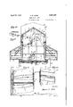
- Fig. 2 is a side view of the amphibious Fig. 3 is a front end view of the amphibious craft.
- Fig. 4 is a longitudinal sectional side view of the craft shown, as being water borne.
- Fig. 5 is a sectional side View of one of the driving wheels disposed at the stern of the craft. The same being taken on line 55,
- Fig. 6 is a side View, partially in section of one of the brake arms disposed adjacent the rear axle, to facilitate the braking of either the brake drums disposed upon therear axle.
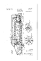
- Fig. 7 is. a top plan view, partially in section, ofthe assembled device.
- Fig. 8 isa fragmentary sectlonal plan View of the driving mechanism. Thesame being taken on line 88, of Fig. 4, looking in the direction indicated.
- FIG. 9 is a fragmentary diagrammatical layout of the driving wheels, and of the rudder. This view being made to illustrate the position of the rudder relative to the driving wheels, in order to develop water'currents that'will give maximum steering capacity to the craft.
- Fig. 10 is a sectional end view, of the assembled device. The same being taken on line 10-10, of Fig. 2, looking in the direction indicated.
- I Fig. 11 is asectional plan view, of one of the propeller wheels.
- Fig. 12 is a top plan view. of one of the propeller wheels.
- ig. 13 is a fragmentary perspective side In this view is shown. a fin forwardly projecting from either side of the craft. The same being made to afford greatest facility to the craft, whenbeing operated through a heavy surf.
- My construction is comprised primarily of ahull having a relatively flat primary bottom 1, and having stabilizers 2 and 3 running lon- V and 13 are provided.
- the lookout lights are rearwardly sloping both vertical and athwart ship in order to offer a minimum of resistance in the passing of the same through a heavy surf.
- the top'of the wheel house is also sloping as illustrated at 14 and 15 to offer mini mum of pounding resistance in the event that heavy breakers are encountered in the operation of the ship.
- a door 16 is provided at one, or more sides of the wheel house to facilitate admittance, and exit from the craft.
- a plurality of dead lights, or port lights 17 are provided in spaced relationship longitudinally of the cabin 18.
- top surfaces 19 and 20 of the cabin are also sloping to facilitate operation in heavy surfs that may encounter the craft in its operation.
- a plurality of seats 21 are provided for the use of passengers and occupants...
- a reversible prime mover having a multiple of speeds, as a hydrocarbon engine 22 is disposed in the forward end of the craft.
- a radiator 23 of usual form is provided in order to maintain the same in suitably cooled condition.
- a tail shaft 24 runs from the prime mover through the stern plates 25 of the craft and cheek plates 26, as illustrated inFig. 8, are secured to the stern.
- a pair of universal joints 27 and 28 are mounted upon the shaft 24 to give flexibility to the shaft.
- a rear shaft 29 is disposed within the wheel compartment'30 of the stern of the ship, and floating axles are disposed longitudinally of the same that are adapted for being driven by the tail shaft.
- the coacting gears disposed within, the axle, being of standard design are not here shown.
- a pair of brake drums 31 and 32 are disposed upon the respective axle members, and the brake drums are actuated by brake arms, as illustrated in Fig. 6.
- a cheek plate 33 is placed in. registerable alignment with the brake drum and a shaft 34 is journaled within the side Wall of the cheek plate housing.
- An arm 35 is mounted upon one end of the shaft to which a. line 36 is mounted. The line 36 terminating upon its forward end with the brake foot liner 37, disposed adjacent the pilot seat 38.
- a second arm 39 is also mounted upon the shaft 34, and the arm 39 is connected to the brake drum by a link 40.
- a pair of these brake operating assem blies are mounted upon the stern plates 25 one of which is associated with each of the brake drums, in order that braking energy may be applied to either of the axle members.
- the driving wheel shaft 41 illustrated in Fig. 8, is disposed horizontally of the wheel compartment 31.
- the shaft being journaled within a yoke 42, the yoke 42 is pivotally mounted relative to the rear axles.
- the propeller shaft and yoke assembly are suspended upon a line or chain 43.
- the line 43 passes through the hawse pipe 44, the hawse pipe being secured by a flange 45 to the stern wheel deck housing 46 to maintain a watertight connection between the hawse pipe and the deck, through which the suspended member 43 passes.
- the line 43 is trained about supporting pulleys 47, 48 and 49 and terminates upon its forward end about a steering drum 50.
- a speed reducer 51 is associated with the shaft about which the drum 50 is secured and the power for the raising and lowering of the driving wheel assembly is secured by the manipulation of the hand crank 52, that is disposed adjacent the drivers seat.
- the outer end of each of the shafts, disposed within the rear axle is journaled within suitable pillow blocks 53 and 54 and sprockets 55 and 56 are disposed upon their respective axles.
- Sprockets 57 and 58 are disposed upon the propeller shaft 41 and suitable driving elements, as chains 59 and 61, are trained about their respective sprockets.
- a pair of propeller wheels 61 and 62 are also mounted upon the propeller shaft 41.
- the sprockets 57 and 58 are rotatably mounted relative to the propeller shaft 41 and are fixedly secured to the heads of the propeller wheels 61 and 62.
- a plurality of spaced blades 63 disposed upon the wheels comprise the propulsion of the ship when the same is being operated as a water craft. When land is reached the propelling wheels may be lowered to contact the beach, or ground and the same may then be used as land propelling wheels.
- Each of the wheels is independently driven and adapted for being independently braked, so that one of the wheels may be made to stand still while the other is driven in either direction to provide greater facility in the steering of the craft.
- Armed blades 63 are disposed upon the wheels to provide better facility in the gripping of the ground when the same are being used for ground propulsion.
- the inner ends of the respective propelling wheels are spaced apart and the rudder 64 is disposed upon the keelson line, or the longitudinal center line of the ship and midway between the respective ends of the propelling axle 61 and 62.
- the propelling of the propelling wheels in their normal work of propelling the ship forces the water current, as illustrated in the diagrammatical layout of Fig. 9 directly past the rudder 64 and affords maximum steering ability to the rudder.
- the rudder is associated with the stern post 65, the stern post being secured within suitable supports 66 and 67 and a tiller arm 68 is secured to the tiller shaft 69.
- a pair of steering lines 70 and 71 lead from the tiller arm and are trained about suitable pulleys 72 and 73 and run longitudinally of the ship and are trained about pulleys 7 4 and 75 disposed at the forward end of the ship.
- the lines then pass about a drum 76, the drum being adapted for being rotated by hand, through the action of the steering wheel 77.
- a pair of rear supporting wheels 78 and 79 are mounted within the bottom of the hull and are adapted for being driven by the mechanism, illustrated in Fig. 8.
- a pair of driving sprockets 80 and 81 are mounted upon the rear axle and driving sprockets 82 and 83 are mounted upon the rear driving wheel assemblies and suitable driving elements, as driving chains 84 and 85 are trained about the respectivesprockets so that the. land wheels are driven directly from the rear axle.
- Aopair of land wheels 86and 87 are mounted upon the forward end of the ship and are supported upon a front axle 88.
- Steering arms 89 and 90 are associated with the spin"- dles of the front wheels and a connecting rod 91 connects the respectivearms.
- a steering rod 92 connects the arms 89 and 90.
- An arm 93 is disposed upon the lower end of the steering column 94.
- the steering column passes'sthrough a stufling box and terminates and is adapted for being manipulated by a steering wheel 95, that is disposed adjacent the seat of the pilot.
- a pair of fins 96 and 97 are disposed upon 9 the oppositely disposed sides of the. forward end of the ship. These fins are secured to a commonv shaft 98.
- the purpose and object of the fins is to stabilize the forward end of the ship when entering a heavy swell or breaker, or wave, so that the angle of repose of a fin will predetermine the action of the water upon'the forward end of the ship itself.
- the fins of the shaft are adapted for being manipulated from the inside of the ship. Since the front land wheels are adapted for being steered by the master of the ship they mayact as rudders when the ship is being propelled in the water. This will greatly aid in the turning of the ship because there will be rudders on either side of the front end of the ship and a rudder at the stern end of the ship.
- a wheel house upwardly extending from the primary deck of the hull, and adjacentthe forward end of the hull, a reversible prime mover disposed within the forward end of the hull, a tail shaft rearwardly extending from the prime mover, and adapted for driving a rear axle disposed within the stern wheel compartment of the ship, a yoke rockably disposed about the rear axle housing, a shaft fixedly disposed within the yoke, a pair of stern stern wheels mounted upon the shaft, means for driving each of the stern wheels independently from the rear axle, manually operable means for predetermining the driving elevation of the stern wheel assembly, and a pair of supporting wheels disposed at either end of the side of the hull, one of said pairs being adapted for being power driven, and the Other of the pair of wheels beingsteered from within the hull.
- a hull a reversible multipled speed power unit disposed within the hull, passenger cabin comprising the major portion of thehull, a stern wheel compartment disposed adjacent the rear end of the hull, a stern wheel mounted within a yoke suspended within the hull and adapted for being driven by the prime mover, means adapting the'stern wheel for serving the dual purpose of driving the hull as a water wheel or as a traction wheel, power driven supporting -wheels disposed adjacent the stern wheel compartment, and a pair of supporting and steering wheels disposed adjacent the underside of the forward end of the hull.
- a hull a reversible multipled speed prime mover disposed within the hull, a stern wheel housing disposed within and adjacent the stern of the hull, a plurality of power driven stern wheels disposed within the stern wheel housing, means for driving either one of the wheels independently of the other, means adapted for facilitating the stern wheels to be used for propelling the hull by water or land propulsion, power driven supporting wheels disposed beneath thehull and adjacent the stern wheel compartment of the hull, and a pair of supporting wheels adapted for being steered from within the hull disposed beneath and adjacent the forward end of the hull.
Description
April 12, 1932. M. E. HOWE AMPHIBIOUS CRAFT Filed May 4, 1951 4 Sheets-Sheet gwoentop Myron E HOW? April 12, 1932. M. E. HOWE 1,853,357
AMPHIBIOUS CRAFT Filed May 4, 1951 r 4 Sheets-Sheet 2 amnion I l Myron E. Home l :HPIWQ A rii 12, 1932. M. E. HOWE AMPHIBIOUS CRAFT Filed May 4, 1951 4 sheets-sheet 3 Myra)? .E. Howe.
April 12, 1932. M. E. HOWE 1,853,357
AMPHIBIOUS CRAFT Filed May 4, 1931 4 Sheets-Sheet 4 Patented Apr. 12, 1932 UNET STTES MYRON EMMETT HOWE, OFOCEANSIDE, onneon AMPHIBIOUS CRAFT Application filed May 4, 1931. Serial No. 534,903.
My invention is related to a combination of land and water craft for use upon the shore and particularly along the beaches of lakes and at the ocean side. It may be used for pleasure, for transportation purposes, and it is believed it will be found particularly useful in life saving operations, in the passing from the land through the breakers to the open water of the sea, or lake.
The device is amphibious to the extent that it may be operated as a water craft, or as a land craft, and is so designed that it may be made to operate successfully in passing from the land to the sea, or from the sea to the land.
mounted within a yoke disposed at the stern of the ship that are power driven. Either of the propeller wheels may be independently driven and in either direction' The stern wheels are adapted for driving the ship as a water craft, and are so made that they will rest directly upon the ground and be made to propel the ship in the intervening space between land and water, and where firm footing and foundation is not obtainable. A
prime mover, as a hydrocarbon engine, is disposed at the forward end of the vessel to afford locomotion to the craft. A plurality of seats are provided within the cabin of the craft for the use of occupants. Dead lights, or ports lights are provided to afford lookout privileges to the occupants of the ship. At least one door is provided for ingress and egress. A tiller post is vertically disposed within the stern of the vessel to which a rudder is attached, on its lower end and a tiller arm is attached to its upper end with suitable lines running longitudinally of the ship'and terminating at the seat of the pilot to facilitate the steering of the vessel. The
craft.
rudder is disposed adjacent and at'the rear of the propeller wheel and is so located that the water from the wheel may be made to directly engage upon the rudder to increase thesteering ability of the same.
One of the objects of my invention is to comprise a ship for use as a water craft, or as a land'borne craft and one that may be amphibious in its nature. I
A further objectofmy invention consists in providing a ship so constructed that it will have stability, when being operatedthrough the surf,-and thatmay be used for transportation purposes, for pleasure purposes, and as a life saving equipment.
. A further I object of my. invention consists in so constructing the ship that it willolfer minimum resistance to the passing of the same through the breakers, and through the waves ofa heavy sea. 0
A still further object of my invention consists in so constructing the stern ofthe ship that incoming waves willhave a tendency to boostthe vessel along to terra firma.
Still further objects of my invention consists in so constructing the propelling mechanisms that maximum steering capacity will be available at all times.
Still further objects of my invention consist in so arranging the supporting and driving wheel that a minimum number of openings will be necessary inthe hull through which the steering and driving mechanism pass to thereby facilitatethe.maintaining of the hull in a relatively water tight condition.
With these and incidental objects in view, the invention consists in certain novel features of construction and combination of parts, the essential elements of which are set forth in the appended claims, and a preferred form of embodiment of which is hereinafter shown with reference to the drawings which accompany and form a part of this specification.
In the drawings:
Fig. 1 is a perspective,side view of the ship. I
Fig. 2 is a side view of the amphibious Fig. 3 is a front end view of the amphibious craft.
Fig. 4 is a longitudinal sectional side view of the craft shown, as being water borne.
Fig. 5 is a sectional side View of one of the driving wheels disposed at the stern of the craft. The same being taken on line 55,
of Fig. 12, looking in the direction indicated.
Fig. 6 is a side View, partially in section of one of the brake arms disposed adjacent the rear axle, to facilitate the braking of either the brake drums disposed upon therear axle.
Fig. 7 is. a top plan view, partially in section, ofthe assembled device.
Fig. 8 isa fragmentary sectlonal plan View of the driving mechanism. Thesame being taken on line 88, of Fig. 4, looking in the direction indicated.
' .Fig. 9 is a fragmentary diagrammatical layout of the driving wheels, and of the rudder. This view being made to illustrate the position of the rudder relative to the driving wheels, in order to develop water'currents that'will give maximum steering capacity to the craft.
Fig. 10 is a sectional end view, of the assembled device. The same being taken on line 10-10, of Fig. 2, looking in the direction indicated. I Fig. 11 is asectional plan view, of one of the propeller wheels.
Fig. 12 is a top plan view. of one of the propeller wheels.
a view of the front end of the craft.
ig. 13 is a fragmentary perspective side In this view is shown. a fin forwardly projecting from either side of the craft. The same being made to afford greatest facility to the craft, whenbeing operated through a heavy surf.
I Like reference characters refer to like parts throughout the several Views.
My construction is comprised primarily of ahull having a relatively flat primary bottom 1, and having stabilizers 2 and 3 running lon- V and 13 are provided. The lookout lights are rearwardly sloping both vertical and athwart ship in order to offer a minimum of resistance in the passing of the same through a heavy surf. The top'of the wheel house is also sloping as illustrated at 14 and 15 to offer mini mum of pounding resistance in the event that heavy breakers are encountered in the operation of the ship. A door 16 is provided at one, or more sides of the wheel house to facilitate admittance, and exit from the craft. A plurality of dead lights, or port lights 17 are provided in spaced relationship longitudinally of the cabin 18. The top surfaces 19 and 20 of the cabin are also sloping to facilitate operation in heavy surfs that may encounter the craft in its operation. A plurality of seats 21 are provided for the use of passengers and occupants... A reversible prime mover having a multiple of speeds, as a hydrocarbon engine 22 is disposed in the forward end of the craft. In order to maintain the same in suitably cooled condition a radiator 23 of usual form is provided. A tail shaft 24 runs from the prime mover through the stern plates 25 of the craft and cheek plates 26, as illustrated inFig. 8, are secured to the stern. A pair of universal joints 27 and 28 are mounted upon the shaft 24 to give flexibility to the shaft. A rear shaft 29 is disposed within the wheel compartment'30 of the stern of the ship, and floating axles are disposed longitudinally of the same that are adapted for being driven by the tail shaft. The coacting gears disposed within, the axle, being of standard design are not here shown. A pair of brake drums 31 and 32 are disposed upon the respective axle members, and the brake drums are actuated by brake arms, as illustrated in Fig. 6. A cheek plate 33 is placed in. registerable alignment with the brake drum and a shaft 34 is journaled within the side Wall of the cheek plate housing. An arm 35 is mounted upon one end of the shaft to which a. line 36 is mounted. The line 36 terminating upon its forward end with the brake foot liner 37, disposed adjacent the pilot seat 38. The oppositely disposed end of the line is secured to the'arm 35. A second arm 39 is also mounted upon the shaft 34, and the arm 39 is connected to the brake drum by a link 40. A pair of these brake operating assem blies are mounted upon the stern plates 25 one of which is associated with each of the brake drums, in order that braking energy may be applied to either of the axle members.
The driving wheel shaft 41, illustrated in Fig. 8, is disposed horizontally of the wheel compartment 31. The shaft being journaled within a yoke 42, the yoke 42 is pivotally mounted relative to the rear axles. The propeller shaft and yoke assembly are suspended upon a line or chain 43. The line 43 passes through the hawse pipe 44, the hawse pipe being secured by a flange 45 to the stern wheel deck housing 46 to maintain a watertight connection between the hawse pipe and the deck, through which the suspended member 43 passes. The line 43 is trained about supporting pulleys 47, 48 and 49 and terminates upon its forward end about a steering drum 50.
A speed reducer 51 is associated with the shaft about which the drum 50 is secured and the power for the raising and lowering of the driving wheel assembly is secured by the manipulation of the hand crank 52, that is disposed adjacent the drivers seat. The outer end of each of the shafts, disposed within the rear axle is journaled within suitable pillow blocks 53 and 54 and sprockets 55 and 56 are disposed upon their respective axles.
Sprockets 57 and 58 are disposed upon the propeller shaft 41 and suitable driving elements, as chains 59 and 61, are trained about their respective sprockets. A pair of propeller wheels 61 and 62 are also mounted upon the propeller shaft 41. The sprockets 57 and 58 are rotatably mounted relative to the propeller shaft 41 and are fixedly secured to the heads of the propeller wheels 61 and 62. A plurality of spaced blades 63 disposed upon the wheels comprise the propulsion of the ship when the same is being operated as a water craft. When land is reached the propelling wheels may be lowered to contact the beach, or ground and the same may then be used as land propelling wheels. Each of the wheels is independently driven and adapted for being independently braked, so that one of the wheels may be made to stand still while the other is driven in either direction to provide greater facility in the steering of the craft. Armed blades 63 are disposed upon the wheels to provide better facility in the gripping of the ground when the same are being used for ground propulsion. The inner ends of the respective propelling wheels are spaced apart and the rudder 64 is disposed upon the keelson line, or the longitudinal center line of the ship and midway between the respective ends of the propelling axle 61 and 62. The propelling of the propelling wheels in their normal work of propelling the ship, forces the water current, as illustrated in the diagrammatical layout of Fig. 9 directly past the rudder 64 and affords maximum steering ability to the rudder. The rudder is associated with the stern post 65, the stern post being secured within suitable supports 66 and 67 and a tiller arm 68 is secured to the tiller shaft 69.
A pair of steering lines 70 and 71 lead from the tiller arm and are trained about suitable pulleys 72 and 73 and run longitudinally of the ship and are trained about pulleys 7 4 and 75 disposed at the forward end of the ship. The lines then pass about a drum 76, the drum being adapted for being rotated by hand, through the action of the steering wheel 77.
A pair of rear supporting wheels 78 and 79 are mounted within the bottom of the hull and are adapted for being driven by the mechanism, illustrated in Fig. 8.
A pair of driving sprockets 80 and 81 are mounted upon the rear axle and driving sprockets 82 and 83 are mounted upon the rear driving wheel assemblies and suitable driving elements, as driving chains 84 and 85 are trained about the respectivesprockets so that the. land wheels are driven directly from the rear axle.
Aopair of land wheels 86and 87 are mounted upon the forward end of the ship and are supported upon a front axle 88. Steering arms 89 and 90 are associated with the spin"- dles of the front wheels and a connecting rod 91 connects the respectivearms. A steering rod 92 connects the arms 89 and 90. An arm 93 is disposed upon the lower end of the steering column 94. The steering column passe'sthrough a stufling box and terminates and is adapted for being manipulated by a steering wheel 95, that is disposed adjacent the seat of the pilot.
A pair of fins 96 and 97 are disposed upon 9 the oppositely disposed sides of the. forward end of the ship. These fins are secured to a commonv shaft 98. The purpose and object of the fins is to stabilize the forward end of the ship when entering a heavy swell or breaker, or wave, so that the angle of repose of a fin will predetermine the action of the water upon'the forward end of the ship itself. The fins of the shaft are adapted for being manipulated from the inside of the ship. Since the front land wheels are adapted for being steered by the master of the ship they mayact as rudders when the ship is being propelled in the water. This will greatly aid in the turning of the ship because there will be rudders on either side of the front end of the ship and a rudder at the stern end of the ship. I
While the form of mechanism herein shown and described is admirably adapted to fulfill the objects primarily stated, it is to be understood that it is not intended to confine the invention to the one form of embodiment herein shown and described, as it is suscep tible of embodiment in various forms, all coming within the scope of the claims which follow.
What I claim is:
1. In a device of the class described, the combination of a hull, stabilizers disposed longitudinally of the hull, and at either side thereof, a wheel house upwardly extending from the primary deck of the hull, and adjacentthe forward end of the hull, a reversible prime mover disposed within the forward end of the hull, a tail shaft rearwardly extending from the prime mover, and adapted for driving a rear axle disposed within the stern wheel compartment of the ship, a yoke rockably disposed about the rear axle housing, a shaft fixedly disposed within the yoke, a pair of stern stern wheels mounted upon the shaft, means for driving each of the stern wheels independently from the rear axle, manually operable means for predetermining the driving elevation of the stern wheel assembly, and a pair of supporting wheels disposed at either end of the side of the hull, one of said pairs being adapted for being power driven, and the Other of the pair of wheels beingsteered from within the hull.
2. In a device of the class described, the combination of a hull, a reversible multipled speed power unit disposed within the hull, passenger cabin comprising the major portion of thehull, a stern wheel compartment disposed adjacent the rear end of the hull, a stern wheel mounted within a yoke suspended within the hull and adapted for being driven by the prime mover, means adapting the'stern wheel for serving the dual purpose of driving the hull as a water wheel or as a traction wheel, power driven supporting -wheels disposed adjacent the stern wheel compartment, and a pair of supporting and steering wheels disposed adjacent the underside of the forward end of the hull.
3.- In a device of the class described, the combination of a hull a reversible multipled speed prime mover disposed within the hull, a stern wheel housing disposed within and adjacent the stern of the hull, a plurality of power driven stern wheels disposed within the stern wheel housing, means for driving either one of the wheels independently of the other, means adapted for facilitating the stern wheels to be used for propelling the hull by water or land propulsion, power driven supporting wheels disposed beneath thehull and adjacent the stern wheel compartment of the hull, and a pair of supporting wheels adapted for being steered from within the hull disposed beneath and adjacent the forward end of the hull.
- MYRON EMMETT HOWE.
Priority Applications (1)
| Application Number | Priority Date | Filing Date | Title |
|---|---|---|---|
| US534903A US1853357A (en) | 1931-05-04 | 1931-05-04 | Amphibious craft |
Applications Claiming Priority (1)
| Application Number | Priority Date | Filing Date | Title |
|---|---|---|---|
| US534903A US1853357A (en) | 1931-05-04 | 1931-05-04 | Amphibious craft |
Publications (1)
| Publication Number | Publication Date |
|---|---|
| US1853357A true US1853357A (en) | 1932-04-12 |
Family
ID=24131998
Family Applications (1)
| Application Number | Title | Priority Date | Filing Date |
|---|---|---|---|
| US534903A Expired - Lifetime US1853357A (en) | 1931-05-04 | 1931-05-04 | Amphibious craft |
Country Status (1)
| Country | Link |
|---|---|
| US (1) | US1853357A (en) |
Cited By (1)
| Publication number | Priority date | Publication date | Assignee | Title |
|---|---|---|---|---|
| US2475496A (en) * | 1943-02-15 | 1949-07-05 | Fmc Corp | Amphibian |
-
1931
- 1931-05-04 US US534903A patent/US1853357A/en not_active Expired - Lifetime
Cited By (1)
| Publication number | Priority date | Publication date | Assignee | Title |
|---|---|---|---|---|
| US2475496A (en) * | 1943-02-15 | 1949-07-05 | Fmc Corp | Amphibian |
Similar Documents
| Publication | Publication Date | Title |
|---|---|---|
| US6921304B2 (en) | Amphibious vehicle | |
| RU2555051C2 (en) | Amphibia | |
| CA2471585C (en) | Amphibious vehicle | |
| AU2014309442B2 (en) | Vessel control system with movable underwater wings | |
| KR101473570B1 (en) | Built-engine amphibious airboat | |
| US2274200A (en) | Anticavitation hydrofoil | |
| US2309875A (en) | Amphibian | |
| US3628493A (en) | Impeller wheel for amphibious vehicle | |
| US6666735B2 (en) | Jet drive assist for off-road vehicle with flotation | |
| US2282745A (en) | Vehicle driven boat | |
| US3198158A (en) | Ship maneuvering system and control | |
| US4198917A (en) | Ice-breaking means for ships | |
| US20090156069A1 (en) | Amphibious vehicle | |
| US3335436A (en) | Water-borne vessels | |
| US2049702A (en) | Amphibious surfboat | |
| US3026841A (en) | Amphibian vehicle | |
| US1853357A (en) | Amphibious craft | |
| CN201580549U (en) | Emergency rescue boat with dynamic sail | |
| US2466236A (en) | Amphibious vehicle | |
| RU2350505C1 (en) | Ferry for forward-drive vehicle | |
| US2930340A (en) | Amphibious craft | |
| US2960056A (en) | Roadable boats | |
| US3166039A (en) | Water craft | |
| US1490964A (en) | Combination land and water vehicle | |
| US3101692A (en) | Boat and propulsion means therefor |