US1853339A - Screen molding bead - Google Patents
Screen molding bead Download PDFInfo
- Publication number
- US1853339A US1853339A US458158A US45815830A US1853339A US 1853339 A US1853339 A US 1853339A US 458158 A US458158 A US 458158A US 45815830 A US45815830 A US 45815830A US 1853339 A US1853339 A US 1853339A
- Authority
- US
- United States
- Prior art keywords
- bead
- screen
- base
- base portion
- frame
- Prior art date
- Legal status (The legal status is an assumption and is not a legal conclusion. Google has not performed a legal analysis and makes no representation as to the accuracy of the status listed.)
- Expired - Lifetime
Links
Images
Classifications
-
- E—FIXED CONSTRUCTIONS
- E06—DOORS, WINDOWS, SHUTTERS, OR ROLLER BLINDS IN GENERAL; LADDERS
- E06B—FIXED OR MOVABLE CLOSURES FOR OPENINGS IN BUILDINGS, VEHICLES, FENCES OR LIKE ENCLOSURES IN GENERAL, e.g. DOORS, WINDOWS, BLINDS, GATES
- E06B9/00—Screening or protective devices for wall or similar openings, with or without operating or securing mechanisms; Closures of similar construction
- E06B9/52—Devices affording protection against insects, e.g. fly screens; Mesh windows for other purposes
Definitions
- This invention relates to a metal-screen molding bead member which serves to assist in securing a wire screen or other fabric to a frame.
- the principal object of the invention is to provide a metal bead member adapted to be positioned within the confines of a rabbet formed in a frame, and constructed to cause a portion of the wire screen or other fabric 1 to be forced or worked inwardly into an opening formed in the lower part of the bead member to thereby tighten and anchor the wire screen or other fabric evenly about its perimeter to the frame.
- Another'object is to provide an article formed with two longitudinal hollow bead portions extending therefrom, of which one is provided with a shoulder portion of a height to abut against the wall or shoulder part of a rabbet and lie substantially flush with the face of the frame.
- the invention has as another object to construct an article having a flat base with two spaced longitudinaLbead portions formed thereon in such a manner that the material between the beads is flattened to contact the base portion, and provide a nailing channel portion-
- the invention further aims to provide a construction which will be very economical of manufacture, of attractive appearance and durable in use.
- Fig. l is a front view in elevation of a window screen frame showing the bead device secured thereto;
- Fig. 2 is an oblique projection of the device, showing it secured within a rabbeted frame member or rail; and i Fig. 3 is an enlarged sectional view taken substantially on the line 3-3 of Fig. 1, clearly showing the important points underlying the construction of the bead.
- the screen molding bead device 1 is shown in its adapted position to thereby aid in securing a wirev screen 2. or other fabric which may be used to a frame 3.
- a rabbet having a base portion 5 and a shoulder 6, and within the confines of this raboet the device is adapted to be arranged and secured.
- the device is shown secured within a'rabbet, it is to be understood that the same may also be mounted on the face side of an unrabbeted frame.
- the device in part includes a substantially fiat base portion 7 and an upstanding right angular shoulder part 8, which is adapted to abut against theshouldered face of the rabbet.
- this right angular part 8 is substantially equal to the depth of the rabbet less the thickness of the wire screen 2 to thereby cause the point or part 9 of the device to lie substantially flush with the face of the frame or rail member 4.
- the material comprising the device is also folded or curved around as at 10 and down and across to provide a hollow bead anda flat nailing channel portion or area 11, the latter of which is adapted to contact the base portion 7, as indicated at 12.
- This channel portion is preferably constructed to lie substantially parallel with and contact the base portion of the device, but may, of course, be
- the device is further folded around as at 13 and 14, and under as at 15 to provide a hollow longitudinal head portion; ofwhich the portion 14 is adapted to lie substantially flush with the inner edge of the frame or rail member; and the base portion 15 is adapted to lie substantially in the same plane as the base portion 7 and contact the channel portion, as indicated at 16, contacting similar to the manner iirwhich the base portion 7 is adapted to contact the channel portion as indicated at 12.
- These base portions 7 and 15 are constructed to provide a space or opening 17 into which the wire screen 2 or other fabric is adapted to be crowded.
- opening 17 Provided in the channel portion 11 opposite this. opening 17 are a plurality of holes 18. It will thus be clear that upon securing the bead device in position by means of small nails or brads such as 19, that the screen 2 will be worked or crowded into the opening 17, as indicated at 20, to thereby cause the edges of the screen to be firmly anchored.
- an improved molding bead device is constructed which has many advantages over the wooden bead; and' that the same may be made of various kinds of metals which may be finished in any suitable manner corresponding, if desired, to a particular kind of finish which may be applied to the frame.
- a molding strip formed with head portions, and with its edges turned under to contact at points between the beads.
- a molding strip formed with hollow bead portions, and with its edges folded under in the same plane to provide a fiat base.
- a molding strip formed with hollow bead portions, and with its edges folded under to engage the strip intermediate the beads and thereby provide a base having a longitudinal opening, one bead being larger and formed with a shoulder thereon, and a nailing portion provided between the beads.
- a molding strip formed with its longitudinal edges folded under to en age the strip intermediate its sides to there y provide a fiat base having a narrow opening therein extending the length thereof.
- a molding strip comprised of sheet material, the longitudinal edges of the strip being folded under to engage the body portion of thestrip so as to provide a base and form a narrow opening extending the full length thereof.
Description
April l2,' 1932. w. J. DENNIS SCREEN. MOLDING BEAD Filed May 31, 1950 Q ws an? Patented Apr. 12, 1932.
UNITEPDLQSTATEES WILLIAM J DENNIS, OF CHICAGO, ILLINOIS SCREEN MOLDING BEAD Application filed May 31, 1930. Serial N0. 458,158.
This invention relates to a metal-screen molding bead member which serves to assist in securing a wire screen or other fabric to a frame. I
The principal object of the invention is to provide a metal bead member adapted to be positioned within the confines of a rabbet formed in a frame, and constructed to cause a portion of the wire screen or other fabric 1 to be forced or worked inwardly into an opening formed in the lower part of the bead member to thereby tighten and anchor the wire screen or other fabric evenly about its perimeter to the frame. I
I Another'object is to provide an article formed with two longitudinal hollow bead portions extending therefrom, of which one is provided with a shoulder portion of a height to abut against the wall or shoulder part of a rabbet and lie substantially flush with the face of the frame.
The invention has as another object to construct an article having a flat base with two spaced longitudinaLbead portions formed thereon in such a manner that the material between the beads is flattened to contact the base portion, and provide a nailing channel portion- The invention further aims to provide a construction which will be very economical of manufacture, of attractive appearance and durable in use.
lVith reference to the drawings wherein several views of the screen molding bead device is shown, and wherein the important features of the device are designated by numerals:
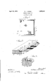
Fig. l is a front view in elevation of a window screen frame showing the bead device secured thereto;
Fig. 2 is an oblique projection of the device, showing it secured within a rabbeted frame member or rail; and i Fig. 3 is an enlarged sectional view taken substantially on the line 3-3 of Fig. 1, clearly showing the important points underlying the construction of the bead.
With reference tothe drawings and particularly to Fig. 1, the screen molding bead device 1 is shown in its adapted position to thereby aid in securing a wirev screen 2. or other fabric which may be used to a frame 3.
In Fig. 2-, one member 4 of the frame is shown provided with a rabbet having a base portion 5 and a shoulder 6, and within the confines of this raboet the device is adapted to be arranged and secured. Although the device is shown secured within a'rabbet, it is to be understood that the same may also be mounted on the face side of an unrabbeted frame. The device in part includes a substantially fiat base portion 7 and an upstanding right angular shoulder part 8, which is adapted to abut against theshouldered face of the rabbet. The height of this right angular part 8 is substantially equal to the depth of the rabbet less the thickness of the wire screen 2 to thereby cause the point or part 9 of the device to lie substantially flush with the face of the frame or rail member 4. The material comprising the device is also folded or curved around as at 10 and down and across to provide a hollow bead anda flat nailing channel portion or area 11, the latter of which is adapted to contact the base portion 7, as indicated at 12. This channel portion is preferably constructed to lie substantially parallel with and contact the base portion of the device, but may, of course, be
altered to some extent, as it will be obvious that it is not essential that it be formed to lie parallel with the base or even contact the same. The device is further folded around as at 13 and 14, and under as at 15 to provide a hollow longitudinal head portion; ofwhich the portion 14 is adapted to lie substantially flush with the inner edge of the frame or rail member; and the base portion 15 is adapted to lie substantially in the same plane as the base portion 7 and contact the channel portion, as indicated at 16, contacting similar to the manner iirwhich the base portion 7 is adapted to contact the channel portion as indicated at 12.
These base portions 7 and 15 are constructed to provide a space or opening 17 into which the wire screen 2 or other fabric is adapted to be crowded. Provided in the channel portion 11 opposite this. opening 17 are a plurality of holes 18. It will thus be clear that upon securing the bead device in position by means of small nails or brads such as 19, that the screen 2 will be worked or crowded into the opening 17, as indicated at 20, to thereby cause the edges of the screen to be firmly anchored.
From the above description, it will be clear- 1 apparent that an improved molding bead device is constructed which has many advantages over the wooden bead; and' that the same may be made of various kinds of metals which may be finished in any suitable manner corresponding, if desired, to a particular kind of finish which may be applied to the frame.
Having thus described my invention, it is obvious that various immaterial modifications may be made in the same without departing from the spirit of my invention; hence, I do not wish to be understood as limiting myself to the exact form, construction, arrangement and combination of parts herein shown and described or uses mentioned.
What I claim as new and desire to secure by Letters Patent is:
1. A molding strip formed with head portions, and with its edges turned under to contact at points between the beads.
2. A molding strip formed with hollow bead portions, and with its edges folded under in the same plane to provide a fiat base.
3. A molding of sheet material folded to provide a base portion, an upwardly extending part which is folded around, down and over to provide a hollow bead and a channel portion, said channel portion adapted to contact said base portion, said material further folded upwardly, down and under to pro vide a bead and base portion, said base portion being adapted to contact said'channel portion and lie in spaced relationship in the same plane with said first-mentioned base portion, and said channel portion provided with a plurality of apertures arranged opposite the space between said base portions.
4. A molding strip formed with hollow bead portions, and with its edges folded under to engage the strip intermediate the beads and thereby provide a base having a longitudinal opening, one bead being larger and formed with a shoulder thereon, and a nailing portion provided between the beads.
5. A molding material folded to provide a base portion, an upwardly extending shoulder part which is folded around, down and over to provide a hollow bead and a flat channel portion, said'channel portion adapted to contact said base portion, said material further folded upwardly, around, and under to provide a bead and base portion, said base portion being adapted to contact said channel portion and lie in spaced relationship in the same plane with said first-mentioned base portion and in a plane parallel with said channel-portion, and said channel portion provided with a plurality of apertures arranged opposite the space between said base por tions.
6. A molding strip formed with its longitudinal edges folded under to en age the strip intermediate its sides to there y provide a fiat base having a narrow opening therein extending the length thereof.
7. A molding strip comprised of sheet material, the longitudinal edges of the strip being folded under to engage the body portion of thestrip so as to provide a base and form a narrow opening extending the full length thereof.
8. The combination of a frame, and a molding strip with a fabric. arranged therebetween, said molding strip being formed of sheet material with its edges folded under to engage the strip so as to provide a base having a narrow opening therein, said opening providing meansfor receiving a portion of the fabric upon the application of said strip to said frame.
In witness whereof I hereunto subscribe my name this 28th day of May, A. D. 1930.
lVILLIAM J. DENNIS.
Priority Applications (1)
| Application Number | Priority Date | Filing Date | Title |
|---|---|---|---|
| US458158A US1853339A (en) | 1930-05-31 | 1930-05-31 | Screen molding bead |
Applications Claiming Priority (1)
| Application Number | Priority Date | Filing Date | Title |
|---|---|---|---|
| US458158A US1853339A (en) | 1930-05-31 | 1930-05-31 | Screen molding bead |
Publications (1)
| Publication Number | Publication Date |
|---|---|
| US1853339A true US1853339A (en) | 1932-04-12 |
Family
ID=23819610
Family Applications (1)
| Application Number | Title | Priority Date | Filing Date |
|---|---|---|---|
| US458158A Expired - Lifetime US1853339A (en) | 1930-05-31 | 1930-05-31 | Screen molding bead |
Country Status (1)
| Country | Link |
|---|---|
| US (1) | US1853339A (en) |
Cited By (1)
| Publication number | Priority date | Publication date | Assignee | Title |
|---|---|---|---|---|
| USD1007006S1 (en) * | 2021-05-16 | 2023-12-05 | Anhui Jiao Yang Soft Door co., LTD | Threshold |
-
1930
- 1930-05-31 US US458158A patent/US1853339A/en not_active Expired - Lifetime
Cited By (1)
| Publication number | Priority date | Publication date | Assignee | Title |
|---|---|---|---|---|
| USD1007006S1 (en) * | 2021-05-16 | 2023-12-05 | Anhui Jiao Yang Soft Door co., LTD | Threshold |
Similar Documents
| Publication | Publication Date | Title |
|---|---|---|
| US1804831A (en) | Two part finishing molding | |
| US1214928A (en) | Window sash or frame. | |
| US1697456A (en) | Jamb-supporting stay | |
| US1853339A (en) | Screen molding bead | |
| US1621213A (en) | Metallic fastener or jamb nail | |
| US2207381A (en) | Metallic window screen | |
| US1379001A (en) | Door and window screen | |
| US1188411A (en) | Collapsible window-screen. | |
| US1842285A (en) | Picture, sign, mirror, and the like | |
| US1437851A (en) | Curtain fixture | |
| US1721629A (en) | Binding strip | |
| US1178581A (en) | Fastener for sheet fabrics. | |
| US587101A (en) | Shelf-bracket | |
| US1798897A (en) | Molding | |
| US1748950A (en) | Carding brush | |
| US1835587A (en) | Combined plaster terminal and molding | |
| US292333A (en) | lobdell | |
| US1525260A (en) | Sash construction | |
| US1611705A (en) | Weather strip | |
| US2165901A (en) | Handbag structure | |
| US2716037A (en) | Fasteners for windows, doors and the like | |
| US1618728A (en) | Metal facing for window openings | |
| US1383975A (en) | Shade-bracket | |
| US1972788A (en) | Weather strip | |
| US1698145A (en) | Screen-wire binder |