US1853331A - Heater - Google Patents
Heater Download PDFInfo
- Publication number
- US1853331A US1853331A US337043A US33704329A US1853331A US 1853331 A US1853331 A US 1853331A US 337043 A US337043 A US 337043A US 33704329 A US33704329 A US 33704329A US 1853331 A US1853331 A US 1853331A
- Authority
- US
- United States
- Prior art keywords
- casing
- heater
- radiator
- air
- floor
- Prior art date
- Legal status (The legal status is an assumption and is not a legal conclusion. Google has not performed a legal analysis and makes no representation as to the accuracy of the status listed.)
- Expired - Lifetime
Links
Images
Classifications
-
- B—PERFORMING OPERATIONS; TRANSPORTING
- B60—VEHICLES IN GENERAL
- B60H—ARRANGEMENTS OF HEATING, COOLING, VENTILATING OR OTHER AIR-TREATING DEVICES SPECIALLY ADAPTED FOR PASSENGER OR GOODS SPACES OF VEHICLES
- B60H1/00—Heating, cooling or ventilating [HVAC] devices
- B60H1/02—Heating, cooling or ventilating [HVAC] devices the heat being derived from the propulsion plant
- B60H1/04—Heating, cooling or ventilating [HVAC] devices the heat being derived from the propulsion plant from cooling liquid of the plant
- B60H1/08—Heating, cooling or ventilating [HVAC] devices the heat being derived from the propulsion plant from cooling liquid of the plant from other radiator than main radiator
Definitions
- This invention relates to heaters, and more particularly a heater especially designed and adapted for use in motor vehicles and of a type utilizing the heat in the water of the 5 engine cooling system.
- Heaters of the kind referred to available in the past can be placed in two classes: those depending upon the draft produced by the engine fan, and those depending for their draft upon the use of an electric motordrivcn fan. Both types are limited to use under the cowl, that is, as front seat heaters. There has, therefore, been a demand for a practical hot water heater designed for rearseat installation, that is, one not relying on a forced air draft, but designed to produce circulation of heated air, instead of simply heating by direct radiation, which, of course,
- a heater which, while particularly suited to rear seat installation, is not necessarily limited to such location, and which comprises a radiator with an enclosure, such as a sheet metal casing, having the inlet and outlet so located wit-h reference to one another and to the radiator that a natural draft is 'produced by thestack or chimney effect of the enclosure or casing.
- a special feature of the heater of my invention resides in the use of a damper in the casing or enclosure arranged to be set at different openin s to correspondingly modulate the heating e ect produced, the said damper being arranged for quick and easy'adjustment by hand to suit conditions or personal preference.
- Figure 1 is a more or less diagrammatic section through the boy of an automobile illustrating the installation of my improved Fig. 5 is a similar view of a still further modified form of heater built into the back of the front seat;
- the reference numeral 6 designates the body of an automobile,and 7 the floor thereof.
- the heater of my invention is indicated generally by-the reference numeral 10, and in this preferred form is a separate unit designed for easy installation behind the front seat, and likewise easy removal if that is ever desired.
- Pipes 11 and 12 are extendedunderneath the floor 7 from beneath the hood of the automobile to and from the heater, the
- pipe 11 being the supply pipe and having connection preferably through a stop cock with a pipe tapped into the water jacket of the motor at a point where the water attains the highest temperature and where it also gets hot immediately upon starting of the motor, namely, in the head of the motor, and the pipe 12 constituting the return pipe and having connection with a hose tapped into the lower outlet hose connection of the car radiator between the latter and its water pump, as, for example, is illustrated in my application Serial No. 311,032, filed October 8, 1928.
- pipes 11 and 12 extend up through holes 13 and 14 bored through the floor 7 for communication with the headers 15 and 16 respectively of a radiator 17. From this much description it will be evident that hot water, or whatever heating medium is used, is supplied to the radiator 17 of the heater 10 from the motor through the pipe 11, and that it flows through the radiator from the header 15 to the header 16 and thence back to the motor through a return pipe 12. In warm weather the heater may be entirely shut off by simply closing the cock in the supply line.
- a heater of this sort may constitute the sole heating means for the car and placed in the position shown or in any other location preferred or found to be suitable, or the same may be provided in conjunction with a front seat heater of the type illustrated and described in my application above referred to, in which latter event, the supply and return pipes 11 and 12 maybe branched off from the same connections with the sup ly and return pipes of the other heater. eaters of this kind are suitable for installation in motor busses, where one could be installed in front of each seat, all being connected in parallel so as to be supplied with the circulating liquid heating medium from the same source.
- the radiator 17 may be of any suitable or preferred type, but is herein illustrated as having what is known as a turbo-tube core consisting of two or more rows of horizontally extending flat tubes 18 connected at their opposite ends with the headers 15 and 16 through header plates 19 and 20 respectively, the latter being of sheet metal and flanged to fit snugly about the rims 21 of said headers, and soldered or otherwise suitably secured thereto for a water-tight connection.
- a turbo-tube core consisting of two or more rows of horizontally extending flat tubes 18 connected at their opposite ends with the headers 15 and 16 through header plates 19 and 20 respectively, the latter being of sheet metal and flanged to fit snugly about the rims 21 of said headers, and soldered or otherwise suitably secured thereto for a water-tight connection.
- the headers 15 and 16 are suitably in the form of heavy castings roviding broad supporting legs 22 arrange to rest on the floor 7 and insure the supporting of the radiator 17 at a predetermined elevation with respect to the floor for a purpose which will presently appear, and also make the radiator absolutely rigid especially when the nuts 13 and 14' threading on the pipes 11 and 12 respectively are tightened against the bottom of the floor 7 lVith the radiator so rigidly supported there is no danger of water leakage due to joints loosening.
- Transverse radiating fins 23 are provided on the tubes 18 to furnish adequate radiation surfaces.
- Plugs 24 and 25 are provided threading into the side walls of the headers 15 and 16 respectively. These plugs, while serving another purpose as will presently appear, are arranged for removal when the system is being filled with water so as to allow the air to escape, it being sufficient if only one plug is removed.
- a sheet metal casing is provided for the enclosure of the radiator 17, the same having one piece 26 bent generally to V-form to provide front, curved top, and back walls to enclose all but the bottom and the ends of the radiator, and end plates 27 and 28 each formed from a single piece of sheet metal of generally triangular form flanged as indicated at 29 to fit over the edges of the part 26 of said casing, the flanges being fastened to the edges of the part 26, suitably by spot-welding, so as to form a unitary casing.
- the plugs 24 and 25 have enlarged acorn heads as shown and are arranged to be passed through holes in the end lates 27 and 28 respectively, whereby to asten the casing to the headers in the osition shown.
- the holes in the plates 27 an 28, for reception of the plugs 24 and 25, are made large enough to receive washers 29, which are either of vellumoid, rubber, or cork material, and steel washers 30 are provided on the outside of the said plates, so as to clamp the latter to the headers in the tightening of the plugs, while the washers 29 are com ressed to prevent leakage.
- washers 29 are either of vellumoid, rubber, or cork material
- the pintle 33 has the damper 32 suitably fixed thereto, and turns in bearings provided in the end plates 27 and 28, the one end of the pintle projecting from the casing and having a knob 35 fixed thereon to permit manual adjustment of the damper.
- the latter is arranged to be set at different openings, and
- Fig. 2 may be held in position by the friction hold of a pointer 36 sweeping over a suitably graduated scale provided on the outside of the end plate 27, said scale serving to indicate the degree of opening of the damper.
- a pointer 36 sweeping over a suitably graduated scale provided on the outside of the end plate 27, said scale serving to indicate the degree of opening of the damper.
- the damper is shown fully closed and, of course, when it is in a position at right angles to this position, it is fully opened. Occupants of the rear seat, where the heater is placed, as shown in Fig. 1, will adjust the damper-by means of the knob to suit conditions or personal preference, it being evident that the controlling of the draft through the casin does not simply function likea shutter, such as in the case of an exhaust heater, where it is simply a matter of controlling the amount.
- the damper in this heater controls the draft and in that way the heating effect is arranged to be regulated.
- the heater 10 in Fig. 4 is one designed for attachment to the back of the front seat of a sedan.
- the casing 26' has a radiator 17 suitably mounted in the lower end thereof between the side w'alls thereof, and a damper 32' suitably mounted on a pint-1e 33 received in bearings in the opposite side walls of the casing at the top thereof just beneath the grilled opening 31, said casing having the marginal edges thereof flanged or otherwise suitably formed for attachment to the back of the front seat 8.
- the casing 26' in this sort of installation may be made anywhere from one and one-half to two and one-half times as high as the casing of a.
- the radiator 17 need not be limited necessarily to the depth of the easing, that is, the dimension between the back of the seat and the back wall of the casing,
- the length .of the radiator may be varied as desired.
- radiator 17 is shown as having connection with supply and return pipes 11', and 12',
- radiator may or may not rest on the floor.
- the heater 10 shown in Fig. 5, is one de-- signed to be built into the back of the front seat 8" where the casing, represented at 26",
- radiator 17 is a permanent back wall, and the radiator 17 is permanently mountedin the lower end of the s ace between said wall and the back of the ront seat proper.
- I claim 1 In a heater for motor vehicles, the combicommunication with asource of hot water or other heating fluid for circulation through said radiator core, and a casing open at the bottom and top, having the radiator core disposed in the open bottom thereof, said casing tt' include ng a plug threading in a hole provided in a wall of one of said headers near the top thereof, the said plug passing through a hole provided in the wall of said casing and serving thereby to secure the casing, said plug-being removable to permit the escape of air when the radiator is being filled with water.
- a hot water radiator core arranged to be disposed substantially horizontally above the floor of the vehicle, a pair of vertically disposed hollow headers having broad bases to afford a goodfooting on the floor of the vehicle and having the opposite ends of said radiator core communicating therewith and supported thereby, supply and return pipes arranged to pass through holes in the floor of the motor vehicle for connection with said headers, said pipes having 5 over the outside of the headers, and
- a heater as set forth in claim 2 wherein said headers have the front and back walls thereof converging upwardly, and wherein said casing is arranged to fit over the headers and has the front and back walls thereof correspondingly converging to fit onto the headers for support thereon, and also including a plug passing through a hole provided in a 'wall of said casing and threading into a hole provided in the wall of one of said headers near the top thereof, said plug serving thereby to secure the casing to the header and being also arranged for removal whereby to permit the escape of air when the radiator is being filled with water.
- an air heating chamber constructed so as to fit the back of a seat and elongated vertically for draft purposes, the same being open at the bottom for inlet of cold air and open at the top for outlet of warm air, and a heating unit disposed transversely of the lower end of said chamber above the cold air inlet so that" the air has contact with the heating unit in its passage upwardly through said chamber to abstract heat therefrom.
- an air heating chamber constructed so as to fit the back of a seat the same being elon ated vertically for draft purposes and having its front and rear walls converging upwardly to conform to the inclination of the back of the seat and afford the desired width at the bottom of the char ber for a large sized heating unit for good heating
- the chamber being open at the bottom for inlet of cold air and open at the top for outlet of warm air
- a heating unit disposed transversely of the lower end of said chamber above the cold air inlet so that the air has contact with the heating unit in its passage upwardly through said chamber to abstract heat therefrom.
- an air heating chamber for the back of a seat elongated vertically for draft purposes the same being open at the bottom for inlet of cold air and open at the top for outlet of warm air
- a heating unit disposed transversely of the lower end of said chamber above the cold air inlet so that the air has contact with the heating unit in its passage upwardly through said chamber to abstract heat therefrom
- the said chamber having the front and back walls thereof conbination of .
- a radiator core arranged to be disposed substantially horizontally above the fioor of the vehicle, and a pair of headers communicating with and supporting the opposite ends of said core, the same being arranged to rest on the floor for support of the radiator core and being arranged to have communication with a source of heating fluid for circulation through said radiator core
- a vertically elongated casing enclosing the radiator core having an open bottom affording easy access of cold air to the radiator core for passage upwardly therethrough, and having the top provided with an opening serving-as a warm air outlet
- a radiator core arranged to be disposed substantially horizontall above the floor of the vehicle and a pair of eaders communicating with and supporting the opposite ends of said core, the same being arranged to rest on the floor for support of the radiator core and being arranged to have communication with a source of heating fluid for circulation through said radiator core, and a casing enclosing the radiator core having an open bottom affording easy access of cold air to the radiator core for passage upwardly therethrough and having the top provided with an openin serving as a warm air outlet, said casing eing conformed substantially triangular in transverse vertical section whereby to permit placing the same on the floor close to the rearwardly inclined back of a seat so as to be out of the way.
- a radiator core arranged to be disposed substantially horizontally above the floor of the vehicle, and a pair of headers communicating with and supportin the opposite ends of said core, the same going arranged to rest on the floor for, support of the -rad1ator core and being arran ed to have in transverse vertical section whereby to permit placing the same on the floor close to the rearwardly inclined back of a seat so as to be out of the way, and a narrow damper disposed transversely of the small upper end of said casing and arranged to regulate the outlet of warm air and correspondingly modulate the draft through said casing.
- a radiator core arranged to be disposed horizontall above the floor of the vehicle, and a pair 0 headers communicatin with and supporting the opposite ends of sai core, the same being arranged to rest on the floor for support of the radiator core and being arranged to have communication with a source of heating fluid for circulation through said radiator core, a vertically elongated casin enclosin the radiator core having an open liottom a ording easy access of cold air to the radiator core for passage upwardly therethrough and having the top provided with an opening serving as a warm ice air outlet, the vertical elon ation of the casing insuring a natural dra of air through said core, and said casing being conformed substantially triangular in transverse vertical section whereby to permit placing the same on the floor close to the rearwardly inclined back of a seat so as to be out of the way, the narrow upper end of said casing being formed substantially semi-circular in transverse vertical section, and
- a casing substantially triangularshaped in cross-section whereby to fit in its allotted space close to the inclined back of the seat, said casing having air inlet and outlet openings in the bottom and top portions thereof respectively, said 'casing bein elongated vertically for draft purposes, an a heating unit in the lower portion of said casing dlsposed transversely with relation to thepath of air travel upwardly through the casing.
- a casing substantially triangular shaped inavertical cross-section whereby to fit in its allotted space close to the inclined back of the seat, said casing havin an air inlet opening in the bottom thereof and having the narrow upper end formed substantially semi-circular in transverse vertical section and 0 en to serve as an air outlet, a heating unit in said casing between the air inlet and outlet, and a narrow longitudinally disposed damper ivotally mounted in the upper end of said casing coaxial with the rounded top portion thereof and arranged in turning to have the outer longitudinal edge move with reference to the opening in said top portion whereb to regulate the outlet of warm air from sai casing.
- a casing substantially triangularshaped in vertical cross-section, whereby to CERTIFICATE OF CORRECTION.
Description
A. H. BATES April 12, 1932.
HEATER Filed Feb. 2, 1929 2 Sheets-Sheet l HEATER Filed Feb. 2, 1929 2 Sheets-Sheet 2 Patented Apr. 12, 1932" UNITED. STATES PATENT OFFICE H. BATES, 01E ROCKFORD, ILLINOIS, ASSIGNOR TO BURD HIGH COMPRESSION RING COMPANY, A CORPORATION- 01' ILLINOIS Banana Application filed February 2, 19:39. Serial No. 337,043.
This invention relates to heaters, and more particularly a heater especially designed and adapted for use in motor vehicles and of a type utilizing the heat in the water of the 5 engine cooling system.
Heaters of the kind referred to available in the past can be placed in two classes: those depending upon the draft produced by the engine fan, and those depending for their draft upon the use of an electric motordrivcn fan. Both types are limited to use under the cowl, that is, as front seat heaters. There has, therefore, been a demand for a practical hot water heater designed for rearseat installation, that is, one not relying on a forced air draft, but designed to produce circulation of heated air, instead of simply heating by direct radiation, which, of course,
is not nearlyso efiicient. It is, therefore, the,
principal object of my invention to provide a heater which, while particularly suited to rear seat installation, is not necessarily limited to such location, and which comprises a radiator with an enclosure, such as a sheet metal casing, having the inlet and outlet so located wit-h reference to one another and to the radiator that a natural draft is 'produced by thestack or chimney effect of the enclosure or casing.
, A special feature of the heater of my invention resides in the use of a damper in the casing or enclosure arranged to be set at different openin s to correspondingly modulate the heating e ect produced, the said damper being arranged for quick and easy'adjustment by hand to suit conditions or personal preference. I l
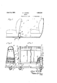
The invention is illustrated in the accompanying drawings, wherein- Figure 1 is a more or less diagrammatic section through the boy of an automobile illustrating the installation of my improved Fig. 5 is a similar view of a still further modified form of heater built into the back of the front seat;
The same or similar reference numerals are applied to corresponding parts throughout the views.
Referring for the time being to Figs. 1 to 3, the reference numeral 6 designates the body of an automobile,and 7 the floor thereof.
8 indicates the front seat and 9 the rear seat.
The heater of my invention is indicated generally by-the reference numeral 10, and in this preferred form is a separate unit designed for easy installation behind the front seat, and likewise easy removal if that is ever desired. Pipes 11 and 12 are extendedunderneath the floor 7 from beneath the hood of the automobile to and from the heater, the
The radiator 17 may be of any suitable or preferred type, but is herein illustrated as having what is known as a turbo-tube core consisting of two or more rows of horizontally extending flat tubes 18 connected at their opposite ends with the headers 15 and 16 through header plates 19 and 20 respectively, the latter being of sheet metal and flanged to fit snugly about the rims 21 of said headers, and soldered or otherwise suitably secured thereto for a water-tight connection. The headers 15 and 16 are suitably in the form of heavy castings roviding broad supporting legs 22 arrange to rest on the floor 7 and insure the supporting of the radiator 17 at a predetermined elevation with respect to the floor for a purpose which will presently appear, and also make the radiator absolutely rigid especially when the nuts 13 and 14' threading on the pipes 11 and 12 respectively are tightened against the bottom of the floor 7 lVith the radiator so rigidly supported there is no danger of water leakage due to joints loosening. Transverse radiating fins 23 are provided on the tubes 18 to furnish adequate radiation surfaces. Plugs 24 and 25 are provided threading into the side walls of the headers 15 and 16 respectively. These plugs, while serving another purpose as will presently appear, are arranged for removal when the system is being filled with water so as to allow the air to escape, it being sufficient if only one plug is removed.
A sheet metal casing is provided for the enclosure of the radiator 17, the same having one piece 26 bent generally to V-form to provide front, curved top, and back walls to enclose all but the bottom and the ends of the radiator, and end plates 27 and 28 each formed from a single piece of sheet metal of generally triangular form flanged as indicated at 29 to fit over the edges of the part 26 of said casing, the flanges being fastened to the edges of the part 26, suitably by spot-welding, so as to form a unitary casing. The plugs 24 and 25 have enlarged acorn heads as shown and are arranged to be passed through holes in the end lates 27 and 28 respectively, whereby to asten the casing to the headers in the osition shown. The holes in the plates 27 an 28, for reception of the plugs 24 and 25, are made large enough to receive washers 29, which are either of vellumoid, rubber, or cork material, and steel washers 30 are provided on the outside of the said plates, so as to clamp the latter to the headers in the tightening of the plugs, while the washers 29 are com ressed to prevent leakage. Now, it will be 0 served that the casing reaches to an appreciable elevation with respect to the radiator enclosed in the lower portion thereof,
and that the top thereof has a grilled opening 31 arranged to serve as the warm air outlet for the heater, the cold air inlet being afforded by the open bottom of the casing where the radiatoris located. This arrangement of the inlet and outlet openings with reference to the radiator produces a stack or chimney effect, and there is, therefore, an appreciable draft produced and consequently an induced circulation of air, generally in the path indicated by the arrows in Fig. 1, that is, warm air rises from the heater and cold air is taken in from the floor levelinto the bottom of the heater, thus causing a circulation substantially as represented. The importance of the stack or chimney effect can best be illustrated by citing an example: Supposing the radiator 17 were simply encased for protection, open at the bottom and top, in which event the heating effect would for the most partbo by direct radiation rather than by induced circulation of heated air; tests involving a comparison of the temperature of the incoming and outgoing water would show a certain heat exchange. I have found that by use of a casing similar to the present one, giving a stack or chimney of say eight inch might, the efficiency of the heater was increased fifty percent, and another heater having a casing of still greater height, say sixteen inches, giving a proportionately greater stack or chimney effect, had one hundred percent better heating efficiency. The importance of this feature can, therefore, be readily appreciated,- and the feature assumes still greater significance when it is considered that by this naturally induced draft, I am enabled to provide a thoroughly practical heater which does not require the use of an electric fan, thus making the heater available at a proportionately lower cost, not to mention the advantage that this sort of heater operates without constituting a drain on the battery. The fact that the heater has the front and back walls converging is a decided advantage because it permits the heater to be placed very close to the back of the front seat Where it is out of the way. In other words, the elongation of the heater casing vertically does not mean that the heater will take up a lot of important space, owing to the fact that the shape of the heater permits of its being placed in the space that is otherwise not used anyway. Furthermore, with the casing made in this form, widest at the bottom, a larger heating unit can be used than would otherwise be the case, and better heating is produced.
and arranged to brush against the inside walls of the casing, and thus seal the gaps between the edges of the damper and the walls of the casing for obvious reasons. The pintle 33 has the damper 32 suitably fixed thereto, and turns in bearings provided in the end plates 27 and 28, the one end of the pintle projecting from the casing and having a knob 35 fixed thereon to permit manual adjustment of the damper. The latter is arranged to be set at different openings, and
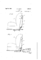
may be held in position by the friction hold of a pointer 36 sweeping over a suitably graduated scale provided on the outside of the end plate 27, said scale serving to indicate the degree of opening of the damper. In Fig. 2
the damper is shown fully closed and, of course, when it is in a position at right angles to this position, it is fully opened. Occupants of the rear seat, where the heater is placed, as shown in Fig. 1, will adjust the damper-by means of the knob to suit conditions or personal preference, it being evident that the controlling of the draft through the casin does not simply function likea shutter, such as in the case of an exhaust heater, where it is simply a matter of controlling the amount.
of air allowed to flow and the draft is some- 35 thing entirely beyond the control of the shut ter; the damper in this heater controls the draft and in that way the heating effect is arranged to be regulated.
The features of the heater of my invention might be embodied in other forms of heaters,
such as those shown in Figs. 4 and 5. The heater 10 in Fig. 4 is one designed for attachment to the back of the front seat of a sedan. 'The casing 26' has a radiator 17 suitably mounted in the lower end thereof between the side w'alls thereof, and a damper 32' suitably mounted on a pint-1e 33 received in bearings in the opposite side walls of the casing at the top thereof just beneath the grilled opening 31, said casing having the marginal edges thereof flanged or otherwise suitably formed for attachment to the back of the front seat 8. The casing 26' in this sort of installation may be made anywhere from one and one-half to two and one-half times as high as the casing of a. heater of the type previously described so as to give a pro portionately greater stack or'chimney eifect and accordingly increases the efficiency of 80 the heater, as was .indicated above. With this form of heater, the radiator 17 need not be limited necessarily to the depth of the easing, that is, the dimension between the back of the seat and the back wall of the casing,
but may be made of any suitable width and similar type available in the past.
will accordingly modulate the heating e ect. The damper, in other words,
set at 'an angle to the vertical, as indicated,
thus giving a greater amount of heat transfer surface in a limited space. The length .of the radiator may be varied as desired. The
similarly as in the form of heater previously described, exceptthat in this case the radiator may or may not rest on the floor.
The heater 10", shown in Fig. 5, is one de-- signed to be built into the back of the front seat 8" where the casing, represented at 26",
is a permanent back wall, and the radiator 17 is permanently mountedin the lower end of the s ace between said wall and the back of the ront seat proper.
It is believed the foregoing description conveys a clear understanding of my invention and its many advantages over heatersof a While reference has been made in the description to certain details of construction, it should be understood that the invention is not to be regarded-as limited thereby, inasmuch as vari-- ous changes might be made without sacrificing the more important advantages referred to; The appended claims have been drawn, therefore, with a view to aifording a degree of protection commensurate with the novelty presented.
I claim 1. In a heater for motor vehicles, the combicommunication with asource of hot water or other heating fluid for circulation through said radiator core, and a casing open at the bottom and top, having the radiator core disposed in the open bottom thereof, said casing tt' inclu ng a plug threading in a hole provided in a wall of one of said headers near the top thereof, the said plug passing through a hole provided in the wall of said casing and serving thereby to secure the casing, said plug-being removable to permit the escape of air when the radiator is being filled with water.
2. In a heater for motor vehicles, the combination of Y a hot water radiator core arranged to be disposed substantially horizontally above the floor of the vehicle, a pair of vertically disposed hollow headers having broad bases to afford a goodfooting on the floor of the vehicle and having the opposite ends of said radiator core communicating therewith and supported thereby, supply and return pipes arranged to pass through holes in the floor of the motor vehicle for connection with said headers, said pipes having 5 over the outside of the headers, and
' outlet.
3. A heater as set forth in claim 2 wherein said casing extends to an appreciable height from the radiator core whereby corres 0ndingly to elevate the outlet opening wit reference to the radiator core and the inlet open ing whereby to insure a natural draft of air through said core.
4. A heater as set forth in claim 2 wherein 'said headers have the front and back walls thereof converging upwardly, and wherein. said casing is arranged to fit over the headers and has the front and back walls thereof correspondingly converging to fit onto the headers for support thereon.
5. A heater as set forth in claim 2 wherein said headers have the front and back walls thereof converging upwardly, and wherein said casing is arranged to fit over the headers and has the front and back walls thereof correspondingly converging to fit onto the headers for support thereon, and also including a plug passing through a hole provided in a 'wall of said casing and threading into a hole provided in the wall of one of said headers near the top thereof, said plug serving thereby to secure the casing to the header and being also arranged for removal whereby to permit the escape of air when the radiator is being filled with water.
6. In an automotive heating means, the combination of an air heating chamber constructed so as to fit the back of a seat and elongated vertically for draft purposes, the same being open at the bottom for inlet of cold air and open at the top for outlet of warm air, and a heating unit disposed transversely of the lower end of said chamber above the cold air inlet so that" the air has contact with the heating unit in its passage upwardly through said chamber to abstract heat therefrom. I
7. In an automotive heating means, the combination of an air heating chamber constructed so as to fit the back of a seat the same being elon ated vertically for draft purposes and having its front and rear walls converging upwardly to conform to the inclination of the back of the seat and afford the desired width at the bottom of the char ber for a large sized heating unit for good heating, the chamber being open at the bottom for inlet of cold air and open at the top for outlet of warm air, and a heating unit disposed transversely of the lower end of said chamber above the cold air inlet so that the air has contact with the heating unit in its passage upwardly through said chamber to abstract heat therefrom.
8. In an automotive heating means, the combination of an air heating chamber for the back of a seat elongated vertically for draft purposes, the same being open at the bottom for inlet of cold air and open at the top for outlet of warm air, a heating unit disposed transversely of the lower end of said chamber above the cold air inlet so that the air has contact with the heating unit in its passage upwardly through said chamber to abstract heat therefrom, the said chamber having the front and back walls thereof conbination of .a radiator core arranged to be disposed substantially horizontally above the fioor of the vehicle, and a pair of headers communicating with and supporting the opposite ends of said core, the same being arranged to rest on the floor for support of the radiator core and being arranged to have communication with a source of heating fluid for circulation through said radiator core, and a vertically elongated casing enclosing the radiator core having an open bottom affording easy access of cold air to the radiator core for passage upwardly therethrough, and having the top provided with an opening serving-as a warm air outlet, the vertical elongation of the casing insuring a natural draft of air through said core, and said casing being conformed substantially triangular in transverse vertical section whereby to permit placing the same on the floor close to the rearwardly inclined back of a seat so as to be out of the way. a
10. In a heater for motor vehicles, the combination of a radiator core arranged to be disposed substantially horizontall above the floor of the vehicle and a pair of eaders communicating with and supporting the opposite ends of said core, the same being arranged to rest on the floor for support of the radiator core and being arranged to have communication with a source of heating fluid for circulation through said radiator core, and a casing enclosing the radiator core having an open bottom affording easy access of cold air to the radiator core for passage upwardly therethrough and having the top provided with an openin serving as a warm air outlet, said casing eing conformed substantially triangular in transverse vertical section whereby to permit placing the same on the floor close to the rearwardly inclined back of a seat so as to be out of the way.
-11. In a heater for motor vehicles, the combination of a radiator core arranged to be disposed substantially horizontally above the floor of the vehicle, and a pair of headers communicating with and supportin the opposite ends of said core, the same going arranged to rest on the floor for, support of the -rad1ator core and being arran ed to have in transverse vertical section whereby to permit placing the same on the floor close to the rearwardly inclined back of a seat so as to be out of the way, and a narrow damper disposed transversely of the small upper end of said casing and arranged to regulate the outlet of warm air and correspondingly modulate the draft through said casing.
12. In a heater for motor vehicles, the combination of a radiator core arranged to be disposed horizontall above the floor of the vehicle, and a pair 0 headers communicatin with and supporting the opposite ends of sai core, the same being arranged to rest on the floor for support of the radiator core and being arranged to have communication with a source of heating fluid for circulation through said radiator core, a vertically elongated casin enclosin the radiator core having an open liottom a ording easy access of cold air to the radiator core for passage upwardly therethrough and having the top provided with an opening serving as a warm ice air outlet, the vertical elon ation of the casing insuring a natural dra of air through said core, and said casing being conformed substantially triangular in transverse vertical section whereby to permit placing the same on the floor close to the rearwardly inclined back of a seat so as to be out of the way, the narrow upper end of said casing being formed substantially semi-circular in transverse vertical section, and a narrow longitudinally disposed damper pivotally mounted in the upper end of said casing coaxial with the rounded top portion thereof and arranged in the turning thereof to have the outer longitudinal edge thereof move with reference to the opening in said top portion whereby to regulate the outlet of warm air fit in its allotted space close to the inclined back of the seat, and a heating-unit in said casing, said casing having air inlet and outlet openings for the admission of cold air to be heated by contact with the. heating unit in said casing and'the discharge of the heated air from said casing.
14. In'a heater for motor vehicles arranged to be disposed on the floor behind a front or other seat, a casing substantially triangularshaped in cross-section whereby to fit in its allotted space close to the inclined back of the seat, said casing having air inlet and outlet openings in the bottom and top portions thereof respectively, said 'casing bein elongated vertically for draft purposes, an a heating unit in the lower portion of said casing dlsposed transversely with relation to thepath of air travel upwardly through the casing.
15. In a heater for motor vehicles arranged to be disposed on the floor behind a front or other seat, a casing substantially triangular shaped inavertical cross-section whereby to fit in its allotted space close to the inclined back of the seat, said casing havin an air inlet opening in the bottom thereof and having the narrow upper end formed substantially semi-circular in transverse vertical section and 0 en to serve as an air outlet, a heating unit in said casing between the air inlet and outlet, and a narrow longitudinally disposed damper ivotally mounted in the upper end of said casing coaxial with the rounded top portion thereof and arranged in turning to have the outer longitudinal edge move with reference to the opening in said top portion whereb to regulate the outlet of warm air from sai casing.
In witness of the foregoing I afiix my signature.
ALBERT H. BATES.
and correspondingly modulate the draftthrough said casing.
13; In a heater for motor vehicles arranged to be disposed on the floor behind a front or other seat, a casing substantially triangularshaped in vertical cross-section, whereby to CERTIFICATE OF CORRECTION.
. Patent No. 1,853,331. April 12, 1932;
} ALBERT H, BATES.
It is hereby certified that error appears in the printed specification of the above nundie'red patent requiring correction as follows: Page 3, line 111, claim 1, strike out the word "including"; and that the said Letten Patent should be rend with this correction therein that the name may conform to the record of the case in the Patent Office.
Signed and sealed this 12th day of July, A. D. i932.
M. J. Moore, (Seal) Acting Connnissioner of Patents.
Priority Applications (1)
| Application Number | Priority Date | Filing Date | Title |
|---|---|---|---|
| US337043A US1853331A (en) | 1929-02-02 | 1929-02-02 | Heater |
Applications Claiming Priority (1)
| Application Number | Priority Date | Filing Date | Title |
|---|---|---|---|
| US337043A US1853331A (en) | 1929-02-02 | 1929-02-02 | Heater |
Publications (1)
| Publication Number | Publication Date |
|---|---|
| US1853331A true US1853331A (en) | 1932-04-12 |
Family
ID=23318860
Family Applications (1)
| Application Number | Title | Priority Date | Filing Date |
|---|---|---|---|
| US337043A Expired - Lifetime US1853331A (en) | 1929-02-02 | 1929-02-02 | Heater |
Country Status (1)
| Country | Link |
|---|---|
| US (1) | US1853331A (en) |
Cited By (4)
| Publication number | Priority date | Publication date | Assignee | Title |
|---|---|---|---|---|
| US2516871A (en) * | 1944-11-08 | 1950-08-01 | Timken Axle Co Detroit | Radiator |
| US4516630A (en) * | 1982-07-27 | 1985-05-14 | Honda Giken Kogyo Kabushiki Kaisha | Motorcycle radiator |
| US4640341A (en) * | 1983-04-19 | 1987-02-03 | Honda Giken Kogyo K.K. | Radiator for vehicles, having improved mountability into vehicles |
| US20060076427A1 (en) * | 2004-10-12 | 2006-04-13 | Schneider Joseph L Jr | Lift truck with heating system |
-
1929
- 1929-02-02 US US337043A patent/US1853331A/en not_active Expired - Lifetime
Cited By (4)
| Publication number | Priority date | Publication date | Assignee | Title |
|---|---|---|---|---|
| US2516871A (en) * | 1944-11-08 | 1950-08-01 | Timken Axle Co Detroit | Radiator |
| US4516630A (en) * | 1982-07-27 | 1985-05-14 | Honda Giken Kogyo Kabushiki Kaisha | Motorcycle radiator |
| US4640341A (en) * | 1983-04-19 | 1987-02-03 | Honda Giken Kogyo K.K. | Radiator for vehicles, having improved mountability into vehicles |
| US20060076427A1 (en) * | 2004-10-12 | 2006-04-13 | Schneider Joseph L Jr | Lift truck with heating system |
Similar Documents
| Publication | Publication Date | Title |
|---|---|---|
| US2037857A (en) | Automobile heater | |
| US1853333A (en) | Heater for motor vehicles | |
| US1853331A (en) | Heater | |
| US1909144A (en) | Heater | |
| US1863882A (en) | Automobile heater | |
| US2477734A (en) | Heating and humidifying apparatus | |
| US1992130A (en) | Heating apparatus for automotive vehicles | |
| KR102471290B1 (en) | heating devices of camping car | |
| US1626400A (en) | Unit for heating and ventilating systems | |
| US2544927A (en) | Water heater | |
| US1903143A (en) | Unit ventilator | |
| US1816604A (en) | Casing or cover for radiators | |
| US2037070A (en) | Furnace | |
| US2475481A (en) | Portable water still | |
| US2568487A (en) | Multiple tube radiator forced circulation air heating furnace | |
| US1913742A (en) | Automobile heater | |
| US1968522A (en) | Automobile heater and motor cooler | |
| US2257721A (en) | Gas water heater | |
| US2174572A (en) | Hot air heater | |
| US3567905A (en) | Hot water space heater | |
| US2126657A (en) | Heated tank for livestock | |
| US1923355A (en) | Car heater | |
| US1507964A (en) | Automobile radiator | |
| US1936615A (en) | Heater | |
| US1767082A (en) | Air heater |