US1853220A - Electrical apparatus - Google Patents
Electrical apparatus Download PDFInfo
- Publication number
- US1853220A US1853220A US370371A US37037129A US1853220A US 1853220 A US1853220 A US 1853220A US 370371 A US370371 A US 370371A US 37037129 A US37037129 A US 37037129A US 1853220 A US1853220 A US 1853220A
- Authority
- US
- United States
- Prior art keywords
- coil
- frame
- casing
- pole pieces
- inductor
- Prior art date
- Legal status (The legal status is an assumption and is not a legal conclusion. Google has not performed a legal analysis and makes no representation as to the accuracy of the status listed.)
- Expired - Lifetime
Links
Images

Classifications
-
- H—ELECTRICITY
- H02—GENERATION; CONVERSION OR DISTRIBUTION OF ELECTRIC POWER
- H02K—DYNAMO-ELECTRIC MACHINES
- H02K21/00—Synchronous motors having permanent magnets; Synchronous generators having permanent magnets
- H02K21/38—Synchronous motors having permanent magnets; Synchronous generators having permanent magnets with rotating flux distributors, and armatures and magnets both stationary
- H02K21/44—Synchronous motors having permanent magnets; Synchronous generators having permanent magnets with rotating flux distributors, and armatures and magnets both stationary with armature windings wound upon the magnets
Definitions
- This invention relates to magneto-electric generators, and more particularly to a high tension magneto of the typeused for ignition purposes in internal combustion engines.
- One of the objects of the present invention is to provide a novel device of this character which is small and compact but efficient and powerful.
- Another object of the invention is the provision of a novel magneto 0f the inductor type using no brushes or slip rings, in which the magnetic circuits are of low reluctance and include few air gaps.
- a further object of the invention is to provide a novel magneto of the inductor type in which a plurality of reversals of fiuxanay be secured during each revolution of the rotor, with the least number of air gaps in the mag-- netic circuit, and in which the elements of the rotor are positively interlocked against any'relative movement.
- Another object of the invention is the provision of a novel magneto in which straight bar magnets are used, thus simplifying the structure and rendering it light, compact and readily manufactured in quantities.
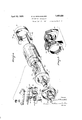
- Fig. 1 is a vertical longitudinal section of of a magneto embodying the present invention
- Fig. 2 is a section taken approximately on the line 2-2 of Fig. 1;
- Fig. 3 is a section taken approximately on the line 33 of Fig. 1;
- Fig. 4 is an expanded perspective view of the elements of the rotor.
- Fig. 5 is a perspective view of the pole pieces which are preferably employed in the structure constituting the subject matter of the invention.
- the present invention comprises a frame 10 of rectangular shape formed of aluminum or other suitable nonmagnetic material, one end of which maybe formed as a separable cap 10.
- the ends of frame 10 are provided with bearings seats 11 1929. Serial No. 370,371.
- the inductor 17 is similarly formed with a ring ortion 25 and arms 26 and 27, and the two in uctors being held in assembled position centered on shaft '18 with their arms overlapping and equally spaced about the shaft by means of body material 19.
- Shaft 18 is provided with an annular shoulder 28 near oneend, and is flattened off near the other end as indicated at 29, where it is provided with shoulders 30 and a transverse pin 31.
- the inductors 16, 17 and the shaft 18 are preferablyniolded in the body 19 by a casting operation, the shoulders 23, 24, 28 and 29 and pin 31 serving to interlock the inductors and shaft with the body of the rotor, and positively prevent relative rotary movement of the parts and radial movement'of the inductor arms, the body material forming a cylindrical core of slightly less diameter than that of the portions 20 and 25.
- shaft 18 is adapted to be rotatably mounted in the bearings 13 and 14, and is provided with a suitable coupling portion 32, for engagement with a driving element.
- Frame 10 is provided on its sides, exteriorly thereof, with rectangular recesses 33 and 34 in which are mounted a pair of magnets 35 and 36 that are preferably built up of suitable magnetized steel bars and having their like poles adjacent each other.
- the magnets 35 and 36 are retained in recesses 33 and 34: by some suitable means such as nonmagnetic plates 35' fixed to the frame 10 by screws 36, one of said plates serving, if desired, as a name plate.
- a generating coil 39 is suitably mounted on the frame 10 as by means of brackets 39' of non-magnetic material clamped against the vertically disposed portions of the laminated core.40 of coil 39 by rivets 41 and fixed to the framelO by screws 42.
- the vertically disposed ends of core extend downwardly, and rest upon a pair of arcuate pole pieces 43 and 44 which are preferably laminated and are placed in quadrantal relation in the frame 10 at the middle portion thereof so as to closely surround the overlapping portions of the inductor arms 21, 22, 26, and 27 as shown in Fig. 3.
- the frame 10 is preferably cast around the pole pieces 37, 38, 43 and 44 so as to form an integral structure.
- the .coil 39 comprises the usual low tension primary and high tension secondary windings with the free ends of each winding grounded and the other end of the high 1 tension winding connected to an insulated output cable 45.
- a housing member 46of suitable non-magnetic material for coil 39 is mounted on frame 10 as by means of screws 47, and is provided at one end with an opening 48 throu h which extends a suitable insulating bush1ng'49 forcable 45.
- a metal cap 50 may be used to clamp the insulating terminal 49 to the magneto frame or housing.
- a metal disc 52 is soldered to the inner end of cable 45 in order to provide a suitable contact with the end of the secondary coil. Disc 52 also serves to hold the cable 45 in operative position so that it can not be pulled away from engagement with the secondary coil.
- high tension cable 45 is enclosed in a metallic sheath or braid 51 which terminates at and is suitably attached to metal cap 50.
- This arrangement provides an electro-static shield for the high tension cable and terminal.
- a condenser 53 is mounted beside the coil 37 across the contact points, to be described hereafter, as is the customarypractice.
- a cam member 54 is mounted on one end of shaft 18, being non-rotatably attached to the rotor 15 as by'screws 55. This cam is adapted to actuate a follower .56 of fiber or other suitable insulating material which proframe 10 as by means of screws 63.
- a spring arm 64 is also mounted on the binding post 62 above the contact arm, having openings 67 which hold the cam follower 56 to the contact arm 57, and being so tensioned as to normally press the contact 59 into engagement with the ground contact 60.
- Openings 68 are tapped in the base of casing 10 whereby the magneto may bebolted upon a suitable bracket or shelf, with the shaft 18 in driving connection with a suitable rotatable part driven from the engine.
- the inductor arms 21 and 22 are always of one polarity,-while the inductor arms 26 and 27 are always of the opposite polarity.
- the inductor arms 21 and 22 are north poles and arms 26 and 27 are south poles
- the flux is frd'm the north poles of the magnets 35 and 36 through the annular piece 43 to the inductor arm 27 and through '65 and 66 to admit the head of the rivets the annular pole piece 37 to the. south poles of magnets 35 and 36.
- the flux traverses the coil from the inductor arm 21 through pole piece 43 and through the core40 of the coil in a reverse direction and out through the pole iece 44 and inductor arm 27. It will thus eseen that there are four reversals of flux through the coil 39 during each revolution of the rotor 15.
- the cam member 54 is provided with four lobes 54 which are arranged to operate the movable contact member 59 to open the primary circuit of coil 39 during the time that the flux through the coil 39 is changingmost rapidly, and therefore the heaviest current is flowing through the primary of said coil.
- the interruption of the primary current induces a current of high voltage in the secondary, of coil 39 which is conducted out through the cable 45 to the ignition system of the engine, returning through the body of the engine and the casing of the magneto.
- a casing having pockets on opposite sides, permanent magnets mounted in said pockets of said casing with like poles ateach end thereof, pole pieces in said casing extending into said pockets for connecting the like poles of the magnets, an induction coil mounted on said casing and having pole pieces set in the casing intermediate the first mentioned pole pieces, an inductor member rotatably mounted in said casing and arranged when rotated to cause the flux between said first mentioned pole pieces to reciprocate through the coil, and a housing for said coil mounted on said casing.
- a magneto a non-magnetic casing
- permanent bar ma nets mounted on opposite sides of the casingwith like poles at each end thereof, annular magnetic pole pieces seated 'in the ends of said casing connecting the like poles of the magnets, an induction coil mounted on said casing and having arcuate pole pieces set in the casing intermediate the annular pole nieces and an inductor member rotatably mounted in said casing and arranged when rotated to cause the flux between the annular pole pieces to reciprocate through the coil.
- a non-magnetic frame of generally rectangular form annular magnetic pole pieces in the ends of said frame, areuate pole pieces located medially of the frame, said frame having longitudinal recesses in the sides thereof, and permanent bar.
- magnets located in said recesses witn like poles in contact with the annular pole pieces and with a central portion spaced from the arcuate pole pieces.
- a magneto a hollow frame, a permanent field magnet mounted thereon, a generating coil mounted on said frame, arotor within the frame having inductor members adapted to magnetically connect the poles of the magnet to the pole pieces of the coil, said connections being reversed a plurality of times during each revolution of the rotor, a. cam fixed on said rotor having 9. corresponding plurality of lobes, and circuit breaking means for said coil mounted on said frame and having a cam follower adapted to be actuated by said cam.
- a magneto a frame, permanent field magnets mounted on the sides of the frame, a generating coil mounted on the casing, a
- a rotor comprising a pair of coaxial in uctor members having spaced overlapping arms, a shaft and a body portion connecting the inductors to the shaft, a cam member mounted on the shaft and having a plurality of lobes corresponding to the inductor arms and bearing a fixed angular relation thereto, and means for rigidly attaching the cam member directly to the body portion.
- a plurality of permanent field magnets a stationary generating coil, a frame adapted to carry said magnets and coil and having pole pieces for said magnets and for said coil molded therein, a rotor within said frame having inductors molded therein adapted to magnetically connect the pole pieces of the coil alternately to the field pole pieces, circuit breaking means mounted externally on said frame, a cover for said coil and circuit breaking means and means on said rotor for actuating said circuit breaking means.
- a magneto a hollow casing having pockets on opposite sides, annular pole pieces carried by the casing at each end and exposed on the inner surface of the casing and extending through the casing into the pockets, bar magnets within the pockets having like poles at the same ends and contacting with the annular pole pieces extending into the pockets, an induction coil mounted on said casing and having a core the ends of which are bent at an angle and extend to the casing, arcuate pole pieces set in the casing intermediate the annular pole pieces and in contact with the extending portions of the core, and an inductor member rotatably mounted in said casing and arranged, when rotated, to cause the flux between the annular pole pieces to reciprocate through the core of the coilby way of the arcuate pole pieces to induce a current in said coil.
Description
April 1932. E. B. NOWOSIELSKI ELECTRICAL APPARATUS Filed June 12. 1929 2 Sheets-Sheet ISnvcntor Gttorncg April 12, 1932. E. B. NOWOSIELSKI ELECTRICAL APPARATUS Filed June 12. 1929 2 Sheets-Sheet 2 Patented Apr. 12, 1932 UNITED STATES PATENT OFFICE EDWARD IB. NOWOSIELSKI, F BLOOMFIELD, NEW JERSEY, ASSIGNOR TO ECLIPSE MA- CHINE COMPANY, OF EL'MILRA HEIGHTS, NEW YORK, A CORPORATION OF NEW YOBK ELECTRICAL APPARATUS Application filed June 12,
This invention relates to magneto-electric generators, and more particularly to a high tension magneto of the typeused for ignition purposes in internal combustion engines.
One of the objects of the present invention is to provide a novel device of this character which is small and compact but efficient and powerful.
- Another object of the invention is the provision of a novel magneto 0f the inductor type using no brushes or slip rings, in which the magnetic circuits are of low reluctance and include few air gaps. M
A further object of the invention is to provide a novel magneto of the inductor type in which a plurality of reversals of fiuxanay be secured during each revolution of the rotor, with the least number of air gaps in the mag-- netic circuit, and in which the elements of the rotor are positively interlocked against any'relative movement.
Another object of the invention is the provision of a novel magneto in which straight bar magnets are used, thus simplifying the structure and rendering it light, compact and readily manufactured in quantities.
Other objects and advantages will be ap parent to those skilled in the art from the following description taken in connection with the accompanying drawings, in which:
Fig. 1 is a vertical longitudinal section of of a magneto embodying the present invention;
Fig. 2 is a section taken approximately on the line 2-2 of Fig. 1;
Fig. 3 is a section taken approximately on the line 33 of Fig. 1;
Fig. 4 is an expanded perspective view of the elements of the rotor; and
Fig. 5 is a perspective view of the pole pieces which are preferably employed in the structure constituting the subject matter of the invention.
In the form shown, the present invention comprises a frame 10 of rectangular shape formed of aluminum or other suitable nonmagnetic material, one end of which maybe formed as a separable cap 10. The ends of frame 10 are provided with bearings seats 11 1929. Serial No. 370,371.
with slight clearance within the frame 10,.
and opposite longitudinally extending arms 21 and 22 having lateral shoulders 23 and 24 formed at their inner edges. The inductor 17 is similarly formed with a ring ortion 25 and arms 26 and 27, and the two in uctors being held in assembled position centered on shaft '18 with their arms overlapping and equally spaced about the shaft by means of body material 19. I
Frame 10 is provided on its sides, exteriorly thereof, with rectangular recesses 33 and 34 in which are mounted a pair of magnets 35 and 36 that are preferably built up of suitable magnetized steel bars and having their like poles adjacent each other. The magnets 35 and 36 are retained in recesses 33 and 34: by some suitable means such as nonmagnetic plates 35' fixed to the frame 10 by screws 36, one of said plates serving, if desired, as a name plate.
of suitable magnetic material are fixed in the casing 10 near the ends thereof, and are formed, as shown in Fig. 5, to have very little clearance around the cylindrical portions 20 and .of the inductor. The ends of bar magnets and 36 directly engage ole pieces 37 and38. It will be seen that y this arrangement the bar magnets 35 and 36 are magnetically coupled together to form in effect asingle hollow magnet, and the inductors 16 and 17 rotate within and are closely coupled, magnetically, to the opposite poles thereof.
' A generating coil 39 is suitably mounted on the frame 10 as by means of brackets 39' of non-magnetic material clamped against the vertically disposed portions of the laminated core.40 of coil 39 by rivets 41 and fixed to the framelO by screws 42. The vertically disposed ends of core extend downwardly, and rest upon a pair of arcuate pole pieces 43 and 44 which are preferably laminated and are placed in quadrantal relation in the frame 10 at the middle portion thereof so as to closely surround the overlapping portions of the inductor arms 21, 22, 26, and 27 as shown in Fig. 3. The frame 10 is preferably cast around the pole pieces 37, 38, 43 and 44 so as to form an integral structure.
The .coil 39 comprises the usual low tension primary and high tension secondary windings with the free ends of each winding grounded and the other end of the high 1 tension winding connected to an insulated output cable 45. A housing member 46of suitable non-magnetic material for coil 39 is mounted on frame 10 as by means of screws 47, and is provided at one end with an opening 48 throu h which extends a suitable insulating bush1ng'49 forcable 45. A metal cap 50 may be used to clamp the insulating terminal 49 to the magneto frame or housing. Preferably a metal disc 52 is soldered to the inner end of cable 45 in order to provide a suitable contact with the end of the secondary coil. Disc 52 also serves to hold the cable 45 in operative position so that it can not be pulled away from engagement with the secondary coil. As shown high tension cable 45 is enclosed in a metallic sheath or braid 51 which terminates at and is suitably attached to metal cap 50.
This arrangement provides an electro-static shield for the high tension cable and terminal. a
A condenser 53 is mounted beside the coil 37 across the contact points, to be described hereafter, as is the customarypractice.
A cam member 54 is mounted on one end of shaft 18, being non-rotatably attached to the rotor 15 as by'screws 55. This cam is adapted to actuate a follower .56 of fiber or other suitable insulating material which proframe 10 as by means of screws 63. A spring arm 64 is also mounted on the binding post 62 above the contact arm, having openings 67 which hold the cam follower 56 to the contact arm 57, and being so tensioned as to normally press the contact 59 into engagement with the ground contact 60.
It will be noted that the inductor arms 21 and 22 are always of one polarity,-while the inductor arms 26 and 27 are always of the opposite polarity. During the operation of the device, if for instance the inductor arms 21 and 22 are north poles and arms 26 and 27 are south poles, when the arm 22 is opposite the pole piece 44 and arm 27 is opposite pole piece 43, then the flux is frd'm the north poles of the magnets 35 and 36 through the annular piece 43 to the inductor arm 27 and through '65 and 66 to admit the head of the rivets the annular pole piece 37 to the. south poles of magnets 35 and 36. When the rotor has turned through a quarter revolution, so thatthe inductor arm 27 is opposite the pole piece 44 and the inductor arm 21 is opposite the pole piece 43, then the flux traverses the coil from the inductor arm 21 through pole piece 43 and through the core40 of the coil in a reverse direction and out through the pole iece 44 and inductor arm 27. It will thus eseen that there are four reversals of flux through the coil 39 during each revolution of the rotor 15. The cam member 54 is provided with four lobes 54 which are arranged to operate the movable contact member 59 to open the primary circuit of coil 39 during the time that the flux through the coil 39 is changingmost rapidly, and therefore the heaviest current is flowing through the primary of said coil. The interruption of the primary current induces a current of high voltage in the secondary, of coil 39 which is conducted out through the cable 45 to the ignition system of the engine, returning through the body of the engine and the casing of the magneto.
Although but one embodiment of the invention has been shown and described in detail, it is to be expressly understood that the illustrated embodiment is not exclusive, and various other embodiments will now suggest themselves to those skilled in the art, while changes may be made in the construction, arrangement and proportions of parts, and certain features used without other features, without departing from the spirit of the invention. Reference is therefore to be had to the claims hereto appended for a definition of the limits of the invention \Vhat is claimed is 1. In a magneto, a casing having pockets on opposite sides, permanent magnets mounted in said pockets of said casing with like poles ateach end thereof, pole nieces in said casing extending into said pockets for connecting the like poles of the magnets, an induction coil mounted on said casing and having pole pieces set in the casing intermediate the first mentioned pole pieces, an inductor member rotatably mounted in said casing and arranged when rotated to cause the flux between said first mentioned pole pieces to reciprocate through the coil, and a housing for said coil mounted on said casing.
2. In a magneto, a non-magnetic casing, permanent bar ma nets mounted on opposite sides of the casingwith like poles at each end thereof, annular magnetic pole pieces seated 'in the ends of said casing connecting the like poles of the magnets, an induction coil mounted on said casing and having arcuate pole pieces set in the casing intermediate the annular pole nieces and an inductor member rotatably mounted in said casing and arranged when rotated to cause the flux between the annular pole pieces to reciprocate through the coil.
3. In a magneto, a non-magnetic frame of generally rectangular form, annular magnetic pole pieces in the ends of said frame, areuate pole pieces located medially of the frame, said frame having longitudinal recesses in the sides thereof, and permanent bar.
magnets located in said recesses witn like poles in contact with the annular pole pieces and with a central portion spaced from the arcuate pole pieces.
4. In a magneto, a hollow frame, a permanent field magnet mounted thereon, a generating coil mounted on said frame, arotor within the frame having inductor members adapted to magnetically connect the poles of the magnet to the pole pieces of the coil, said connections being reversed a plurality of times during each revolution of the rotor, a. cam fixed on said rotor having 9. corresponding plurality of lobes, and circuit breaking means for said coil mounted on said frame and having a cam follower adapted to be actuated by said cam.
5. In a magneto, a frame, permanent field magnets mounted on the sides of the frame, a generating coil mounted on the casing, a
rotor journaled in the frame and having inductor members adapted to magnetically connect the poles of the magnet to the pole pieces of the coil, said connections being reversed a plurality of times during each revolution of the rotor, a cam fixed on said rotor having a corresponding plurality of lobes, and circuit controlling means for said coil comprising an insulated contact arm mounted on said frame, a cam follower on said arm adapted to project through an opening in said frame and cooperate with said cam, and a fixed grounded contact normally engaged by said contact arm.
6. In a ma etc, a rotor comprising a pair of coaxial in uctor members having spaced overlapping arms, a shaft and a body portion connecting the inductors to the shaft, a cam member mounted on the shaft and having a plurality of lobes corresponding to the inductor arms and bearing a fixed angular relation thereto, and means for rigidly attaching the cam member directly to the body portion.
'7. In an electric generator, a plurality of permanent field magnets, a stationary generating coil, a frame adapted to carry said magnets and coil and having pole pieces for said magnets and for said coil molded therein, a rotor within said frame having inductors molded therein adapted to magnetically connect the pole pieces of the coil alternately to the field pole pieces, circuit breaking means mounted externally on said frame, a cover for said coil and circuit breaking means and means on said rotor for actuating said circuit breaking means.
8. In a magneto, a hollow casing having pockets on opposite sides, annular pole pieces carried by the casing at each end and exposed on the inner surface of the casing and extending through the casing into the pockets, bar magnets within the pockets having like poles at the same ends and contacting with the annular pole pieces extending into the pockets, an induction coil mounted on said casing and having a core the ends of which are bent at an angle and extend to the casing, arcuate pole pieces set in the casing intermediate the annular pole pieces and in contact with the extending portions of the core, and an inductor member rotatably mounted in said casing and arranged, when rotated, to cause the flux between the annular pole pieces to reciprocate through the core of the coilby way of the arcuate pole pieces to induce a current in said coil.
In testimony whereof I have signed this specification.
EDWARD B. NOWOSIELSKI.
Priority Applications (1)
| Application Number | Priority Date | Filing Date | Title |
|---|---|---|---|
| US370371A US1853220A (en) | 1929-06-12 | 1929-06-12 | Electrical apparatus |
Applications Claiming Priority (1)
| Application Number | Priority Date | Filing Date | Title |
|---|---|---|---|
| US370371A US1853220A (en) | 1929-06-12 | 1929-06-12 | Electrical apparatus |
Publications (1)
| Publication Number | Publication Date |
|---|---|
| US1853220A true US1853220A (en) | 1932-04-12 |
Family
ID=23459346
Family Applications (1)
| Application Number | Title | Priority Date | Filing Date |
|---|---|---|---|
| US370371A Expired - Lifetime US1853220A (en) | 1929-06-12 | 1929-06-12 | Electrical apparatus |
Country Status (1)
| Country | Link |
|---|---|
| US (1) | US1853220A (en) |
Cited By (3)
| Publication number | Priority date | Publication date | Assignee | Title |
|---|---|---|---|---|
| US2422151A (en) * | 1945-02-10 | 1947-06-10 | Geneto Corp | Single and mutispark magneto |
| US3223866A (en) * | 1960-09-13 | 1965-12-14 | Trw Inc | Alternator |
| US3482130A (en) * | 1967-12-28 | 1969-12-02 | Ford Motor Co | Reluctance pickup speed device for a speedometer cable |
-
1929
- 1929-06-12 US US370371A patent/US1853220A/en not_active Expired - Lifetime
Cited By (3)
| Publication number | Priority date | Publication date | Assignee | Title |
|---|---|---|---|---|
| US2422151A (en) * | 1945-02-10 | 1947-06-10 | Geneto Corp | Single and mutispark magneto |
| US3223866A (en) * | 1960-09-13 | 1965-12-14 | Trw Inc | Alternator |
| US3482130A (en) * | 1967-12-28 | 1969-12-02 | Ford Motor Co | Reluctance pickup speed device for a speedometer cable |
Similar Documents
| Publication | Publication Date | Title |
|---|---|---|
| US1859643A (en) | Magnetic motor | |
| US1853220A (en) | Electrical apparatus | |
| US1275292A (en) | Ignition and lighting apparatus. | |
| US1274115A (en) | Electric generator. | |
| US1993824A (en) | Magneto-electric machine | |
| US2710929A (en) | Magneto | |
| US1545422A (en) | Dynamo-electric machine | |
| US1993825A (en) | Magneto-electric machine | |
| US1401883A (en) | Dynamo-electric generator | |
| US1321158A (en) | Magneto | |
| US778707A (en) | Igniting device for internal-combustion engines. | |
| US2150688A (en) | Magneto | |
| US1027023A (en) | Magneto. | |
| US1938262A (en) | High-tension magneto-electric machine | |
| US1927715A (en) | Magneto-electric generator | |
| US1160995A (en) | Magneto-electric machine. | |
| US1935127A (en) | Magneto | |
| US1693345A (en) | Magneto construction | |
| US2089759A (en) | Electrical apparatus | |
| US460087A (en) | Electric motor | |
| US1907221A (en) | Electric motor | |
| US2300117A (en) | Magneto | |
| USRE14181E (en) | Assighos | |
| US1209003A (en) | Ignition-dynamo. | |
| US947647A (en) | Inductor-generator for ignition purposes. |