US1853099A - Grease or lubricant pumping apparatus - Google Patents
Grease or lubricant pumping apparatus Download PDFInfo
- Publication number
- US1853099A US1853099A US541636A US54163631A US1853099A US 1853099 A US1853099 A US 1853099A US 541636 A US541636 A US 541636A US 54163631 A US54163631 A US 54163631A US 1853099 A US1853099 A US 1853099A
- Authority
- US
- United States
- Prior art keywords
- pump
- grease
- meter
- container
- lubricant
- Prior art date
- Legal status (The legal status is an assumption and is not a legal conclusion. Google has not performed a legal analysis and makes no representation as to the accuracy of the status listed.)
- Expired - Lifetime
Links
- 239000004519 grease Substances 0.000 title description 29
- 238000005086 pumping Methods 0.000 title description 22
- 239000000314 lubricant Substances 0.000 title description 17
- 230000001050 lubricating effect Effects 0.000 description 10
- 238000010276 construction Methods 0.000 description 6
- 241000237858 Gastropoda Species 0.000 description 1
- 230000005540 biological transmission Effects 0.000 description 1
Images

Classifications
-
- F—MECHANICAL ENGINEERING; LIGHTING; HEATING; WEAPONS; BLASTING
- F16—ENGINEERING ELEMENTS AND UNITS; GENERAL MEASURES FOR PRODUCING AND MAINTAINING EFFECTIVE FUNCTIONING OF MACHINES OR INSTALLATIONS; THERMAL INSULATION IN GENERAL
- F16N—LUBRICATING
- F16N13/00—Lubricating-pumps
- F16N13/02—Lubricating-pumps with reciprocating piston
- F16N13/06—Actuation of lubricating-pumps
- F16N13/08—Actuation of lubricating-pumps by hand or foot
Definitions
- This invention relates to grease or lubricant pumping apparatus, and an object of the invention is to provide means whereby the quantity of lubricating grease pumped 5 from a suitable container may be accurately measured;
- An object of the present invention is to provide a lubricating grease pumping apparatus or unit by means of which the quantity of lubricant pumped willbe accurately indicated, thereby eliminating chance or guesswork in such pumping, and insuring that the purchaser receives the quantity of lubricant for which he pays.
- the present invention comprehends the provision of a measuring meter on the discharge side of the pump, through which the lubricating grease passes, and which accurately registers the quantity pumped, and further provides, in combinaair pumped and especially at times when the container is practically empty and the pump sucks a quantity of air thereinto with the lubricant.
- Fig, 1 is a side elevation of the improved pumpmg apparatus.
- Fig. 2 is a top-plan of the improved pumping apparatus.
- Fig. 3 is'a fragmentary section through the improved grease pumping apparatus.
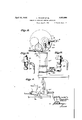
- Fig. 4 is a side elevation of a modified form of the pumping apparatus.
- Fig. 5 is a fragmentary section through the modified form of the apparatus.
- a container 1 is used for containing the lubricating grease such as is usedin differentials, transmissions, etc., about automobiles or analogous machinery, and a pump 2 of any approved construction is attached to the container 1 and has its suction pipe 3 depending into the container.
- the pump piston 4 is reciprocated in the suction pipe 3 through the medium of any approved type of mechanism, by rotation of the handle 5.
- the structure just described is the approved type of dispenser for lubricating grease now commonly in use.
- the grease handle 5 In the present-day dispensing apparatus, the grease handle 5; this, however, is not very accurate because many things cause variations in the i quantity of grease pumped on each turn of the handle, such as, for instance, when the level of the grease in the container 1 reaches the lower endiof the suction pipe 3 and the pump draws or sucks air with slugs of the grease, slippage of the parts or the failure of the operator to make a complete turn or revoluti on of the handle.
- the present invention comprises means for accurately and positively measuring the quantity of lubricating grease delivered by the apparatus, and comprises a meter 10 of any approved construction which is connected to the discharge pipe 11 of the pump 2 and to the outlet of which meter the hose 6 is connected, so that all grease pumped must pass through the meter 10 and be registered thereby before it is delivered.
- the delivered quantit of grease is accurately registered on the ial 12 of the meter.
- meters of this type will meter 10.
- the pipe 15 extends into the conf cause a resistance is set up in the meter,
- tainer 1 and while it is shown in the drawings of small diameter, it is understood that it may be made of any size desirable and may be connected at any convenient point between the meter and the supply of grease in the container 1, to permit the escape of air from the discharge line of the pump prior toits en trance to the meter 10.
- the discharge of air through the bypass 15 will be permitted begreater than the resistance through the bypass 15, owing'to the construction 'of the meter and the air will, therefore, pass out through the bypass and not be recorded or measured. Any lubricating grease which might also pass through the bypass 15 will be returned to the container 1.
- an additional resistance is provided between the bypass 15 and the meter .10, this additional resistance being in the form of a spring loaded .ch'eck valve 20 of any approved form.
- the check valve is placed between the inlet 21 to the meter 10 and the bypass 15, and it may be found desirable to use such additional resistance in instances where relatively thin lubricating grease is being pumped.
- the check valve merely acts in conjunction with the meter to provide resistance and insure the air passing through the bypass 15' and prevent its entrance into and passage through the meter.
- the modified form of the iIVGHlZiOIl is similar to the preferred form previously described.
- bypasses 15 and 15 are shown as extending into the container 1 to a depth in close proximity to the lower end of the pump suction pipe 3, it is to be understood that they may terminate at or close to the top of the container or may open out exteriorly of the container 1, if it is so desired, without departing from the spirit of the present invention.
- the invention is the quantity of not to be limited to the s ecific construction or arrangement of arts 5 own, but that they ma be widely mo ified within the invention de ned by the claims.
- a grease pumping apparatus the combination, with a container and a pump mounted thereon for pumping lubricant from the container, of a measuring meter in the discharge line of the pump, and a bypass pipe connected to the pump discharge between the pump and meter to permit escape of air pumped prior' to its entrance into the meter.
- a grease pumping apparatus the combination, with a container and a pump mounted thereon for pumping lubricant from the container, of a measuring meter in the discharge line of the pump, a bypass pipe connected to the pump discharge between the pump and meter to permit escape of air pumped prior to its entrance into the meter, and a spring loaded check valve in the discharge line of the pump between the pump and meter.
Description
April 12, 1932. 1.. TRAGER ET AL GREASE OR LUBRICANT PUMPING APPARATUS Filed June 2, 19:51
2 Sheets-Sheet 1 INVENTOR A TORNEY L. IRHGEF April 12,1932. L TRAGER ET AL 1,853,099
GREASE 0R LUBRICANT PUMPING APPARATUS Filed June 2. 1931 2 Sheets-Sheet 2 L. Tame ER.-
INVENTOR ATTORNEY HESEVE NM I I Patented Apr. 12, 19321 UNITED STATES PATENT OFFICE 7 LEON, TRAGER AND HARRY F. SEVERN, OF NEWARK, NEW JERSEY, ASSIGNOIRS TO WORTHINGTON PUMP AND MACHINERY CORPORATION, OF NEW YORK, N. Y., A COR- PORATION OF VIRGINIA GREASE OB LUBRICANT PUMPING APPARATUS Application filed June2, 1931. Serial No. 541,636.
This invention relates to grease or lubricant pumping apparatus, and an object of the invention is to provide means whereby the quantity of lubricating grease pumped 5 from a suitable container may be accurately measured;
In pumping semi-hard lubricating grease into various parts of automobiles or analogous machinery, it has heretofore been the practice to rely upon the number of turns of the pump piston operating .handle for ,de-' termining the quantity of such lubricant pumped. This means is not positively accurate and discrepancies occur in the quantity of lubricant pumped, particularly at times when the container is practically empty, often resulting in the purchaser being charged for a greater quantity of the lubricant than he receives. 0 An object of the present invention is to provide a lubricating grease pumping apparatus or unit by means of which the quantity of lubricant pumped willbe accurately indicated, thereby eliminating chance or guesswork in such pumping, and insuring that the purchaser receives the quantity of lubricant for which he pays.
More specifically, the present invention comprehends the provision of a measuring meter on the discharge side of the pump, through which the lubricating grease passes, and which accurately registers the quantity pumped, and further provides, in combinaair pumped and especially at times when the container is practically empty and the pump sucks a quantity of air thereinto with the lubricant.
With these and other objects in view, as may appear from the accompanying specification, the invention consists of various features of construction and combination of parts, which will be first described in connection with the accompanying drawings, showing grease of lubricant pumping apparatusof the preferred form embodying the invention, and the features forming the invention will be specifically pointed out in the claims.
tion with-such an arrangement, means which.
In the drawings:
Fig, 1 is a side elevation of the improved pumpmg apparatus.
Fig. 2 is a top-plan of the improved pumping apparatus.
Fig. 3 is'a fragmentary section through the improved grease pumping apparatus.
Fig. 4 is a side elevation of a modified form of the pumping apparatus.
Fig. 5 is a fragmentary section through the modified form of the apparatus.
Referring more particularly to the drawings, a container 1 is used for containing the lubricating grease such as is usedin differentials, transmissions, etc., about automobiles or analogous machinery, and a pump 2 of any approved construction is attached to the container 1 and has its suction pipe 3 depending into the container. In the drawings the pump piston 4 is reciprocated in the suction pipe 3 through the medium of any approved type of mechanism, by rotation of the handle 5. The structure just described is the approved type of dispenser for lubricating grease now commonly in use. In the present-day dispensing apparatus, the grease handle 5; this, however, is not very accurate because many things cause variations in the i quantity of grease pumped on each turn of the handle, such as, for instance, when the level of the grease in the container 1 reaches the lower endiof the suction pipe 3 and the pump draws or sucks air with slugs of the grease, slippage of the parts or the failure of the operator to make a complete turn or revoluti on of the handle.
The present invention comprises means for accurately and positively measuring the quantity of lubricating grease delivered by the apparatus, and comprises a meter 10 of any approved construction which is connected to the discharge pipe 11 of the pump 2 and to the outlet of which meter the hose 6 is connected, so that all grease pumped must pass through the meter 10 and be registered thereby before it is delivered. The delivered quantit of grease is accurately registered on the ial 12 of the meter. However, owing to its construction, meters of this type will meter 10. The pipe 15 extends into the conf cause a resistance is set up in the meter,
In the modified form of the invention shown in Figures 4 and 5 of: the drawings, an additional resistance is provided between the bypass 15 and the meter .10, this additional resistance being in the form of a spring loaded .ch'eck valve 20 of any approved form. As
noted in the drawings, the check valve is placed between the inlet 21 to the meter 10 and the bypass 15, and it may be found desirable to use such additional resistance in instances where relatively thin lubricating grease is being pumped. The check valve merely acts in conjunction with the meter to provide resistance and insure the air passing through the bypass 15' and prevent its entrance into and passage through the meter. In all other respects the modified form of the iIVGHlZiOIl is similar to the preferred form previously described.
\Vhile the bypasses 15 and 15 are shown as extending into the container 1 to a depth in close proximity to the lower end of the pump suction pipe 3, it is to be understood that they may terminate at or close to the top of the container or may open out exteriorly of the container 1, if it is so desired, without departing from the spirit of the present invention.
From the foregoing description, taken i connection with the accompanying drawings, it will be apparent that the quantity of lubricating grease discharged will be accurately measured, and errors in the computing of the v quantity umped will be eliminated.
It will e understood that the invention is the quantity of not to be limited to the s ecific construction or arrangement of arts 5 own, but that they ma be widely mo ified within the invention de ned by the claims.
What is claimed is: 1. In a grease pumping apparatus, the combination, with a container anda pum mounted thereon for pumping lubricant rom the container, of a measuring meter in the discharge line of the pump, and an air escape in the discharge line of the pump between the pump and meter to permit escape of air pumped prior to its entrance into the meter.
2. In a grease pumping apparatus, the combination, with a container and a pump mounted thereon for pumping lubricant from the container, of a measuring meter in the discharge line of the pump, and a bypass pipe connected to the pump discharge between the pump and meter to permit escape of air pumped prior' to its entrance into the meter.
3. In a grease pumping apparatus,the combination, with a container and a pump mounted thereon-for pumping lubricant from the container, of a measuring meter in the discharge lineof the pump, and a bypass pipe connected to the pump discharge between the pump and meter to permit escape of air pumped prior to its entrance into the meter, said bypass pipe projecting into said container.
4. In a grease pumping apparatus, the combination, with a container and a pump mounted thereon for pumping lubricant from the container, of a measuring meter in the discharge line of the pump, an air escape in the discharge line of the pump between the pump and meterto permit escape of air pumped prior to its entrance into the meter, and a check Valve between the meter and pump in the discharge line of the pump.
5. In a grease pumping apparatus, the combination, with a container and a pump mounted thereon for pumping lubricant from the container, of a measuring meter in the discharge line of the pump, a bypass pipe connected to the pump discharge between the pump and meter to permit escape of air pumped prior to its entrance into the meter, and a spring loaded check valve in the discharge line of the pump between the pump and meter.
In testimony whereof we aflix our signatures.
HARRY F. SEVERN. LEON TRAGER.
Priority Applications (1)
| Application Number | Priority Date | Filing Date | Title |
|---|---|---|---|
| US541636A US1853099A (en) | 1931-06-02 | 1931-06-02 | Grease or lubricant pumping apparatus |
Applications Claiming Priority (1)
| Application Number | Priority Date | Filing Date | Title |
|---|---|---|---|
| US541636A US1853099A (en) | 1931-06-02 | 1931-06-02 | Grease or lubricant pumping apparatus |
Publications (1)
| Publication Number | Publication Date |
|---|---|
| US1853099A true US1853099A (en) | 1932-04-12 |
Family
ID=24160418
Family Applications (1)
| Application Number | Title | Priority Date | Filing Date |
|---|---|---|---|
| US541636A Expired - Lifetime US1853099A (en) | 1931-06-02 | 1931-06-02 | Grease or lubricant pumping apparatus |
Country Status (1)
| Country | Link |
|---|---|
| US (1) | US1853099A (en) |
Cited By (1)
| Publication number | Priority date | Publication date | Assignee | Title |
|---|---|---|---|---|
| US3330157A (en) * | 1964-08-11 | 1967-07-11 | Liquid Controls Corp | Liquid transmission system |
-
1931
- 1931-06-02 US US541636A patent/US1853099A/en not_active Expired - Lifetime
Cited By (1)
| Publication number | Priority date | Publication date | Assignee | Title |
|---|---|---|---|---|
| US3330157A (en) * | 1964-08-11 | 1967-07-11 | Liquid Controls Corp | Liquid transmission system |
Similar Documents
| Publication | Publication Date | Title |
|---|---|---|
| US1853099A (en) | Grease or lubricant pumping apparatus | |
| DE1653882A1 (en) | Rotary pump for pumping liquids with solid impurities | |
| US2017345A (en) | Pumping and metering system for tank trucks | |
| US1886022A (en) | Liquid dispensing and measuring device | |
| US2700488A (en) | Antiaeration control mechanism in fluid dispensing apparatus | |
| DE720485C (en) | Conveyor device for liquids | |
| US1599081A (en) | Apparatus for dispensing liquids through meters | |
| US1737929A (en) | Liquid delivery and pumping apparatus | |
| US2360093A (en) | Pump for delivering measured volumes of liquid under pressure | |
| US1846135A (en) | Automatic oil dispenser | |
| US2275355A (en) | Pump and air separator | |
| US2229844A (en) | Pump | |
| US1816821A (en) | Liquid pump | |
| US1369517A (en) | Grease and oil dispensing apparatus | |
| USRE19384E (en) | Liquid pump | |
| US1839609A (en) | Dispensing apparatus | |
| US2358629A (en) | Liquid dispensing apparatus | |
| US1587912A (en) | Lubricant-dispensing apparatus | |
| US1792208A (en) | Fluid-handling apparatus | |
| US2300145A (en) | Liquid dispensing apparatus | |
| US872943A (en) | Self-measuring pump. | |
| US1862311A (en) | Filling station apparatus | |
| US2117922A (en) | Indicator and metering device | |
| US1871128A (en) | Pumping apparatus | |
| US1345733A (en) | aykes |