US1853096A - Hydraulic elevator - Google Patents
Hydraulic elevator Download PDFInfo
- Publication number
- US1853096A US1853096A US495069A US49506930A US1853096A US 1853096 A US1853096 A US 1853096A US 495069 A US495069 A US 495069A US 49506930 A US49506930 A US 49506930A US 1853096 A US1853096 A US 1853096A
- Authority
- US
- United States
- Prior art keywords
- elevator
- pump
- motor
- reservoir
- solenoid
- Prior art date
- Legal status (The legal status is an assumption and is not a legal conclusion. Google has not performed a legal analysis and makes no representation as to the accuracy of the status listed.)
- Expired - Lifetime
Links
Images
Classifications
-
- B—PERFORMING OPERATIONS; TRANSPORTING
- B66—HOISTING; LIFTING; HAULING
- B66B—ELEVATORS; ESCALATORS OR MOVING WALKWAYS
- B66B1/00—Control systems of elevators in general
- B66B1/02—Control systems without regulation, i.e. without retroactive action
- B66B1/04—Control systems without regulation, i.e. without retroactive action hydraulic
-
- Y—GENERAL TAGGING OF NEW TECHNOLOGICAL DEVELOPMENTS; GENERAL TAGGING OF CROSS-SECTIONAL TECHNOLOGIES SPANNING OVER SEVERAL SECTIONS OF THE IPC; TECHNICAL SUBJECTS COVERED BY FORMER USPC CROSS-REFERENCE ART COLLECTIONS [XRACs] AND DIGESTS
- Y10—TECHNICAL SUBJECTS COVERED BY FORMER USPC
- Y10S—TECHNICAL SUBJECTS COVERED BY FORMER USPC CROSS-REFERENCE ART COLLECTIONS [XRACs] AND DIGESTS
- Y10S60/00—Power plants
- Y10S60/911—Fluid motor system incorporating electrical system
Definitions
- This invention relates to improvement in hydraulic elevators and has especial relation to a device of this kind in which the elevator is' raised by pumping liquid into the elevator cylinder. It further relates particularly to a device of this kind in which the pump is more or less remote from the elevator and in which the actuation of the pump is governed by remote control. It further relates to a device 100i this kind 'in which the raising fluid is in a closed circuit and particularly to a device in which the pump and the motor therefor are enclosed in the iiuid reservoir and a release valve interlocked with the motor control is .1.5 also carried by the Huid reservoir.y
- the objects of the present device are:
- Fig. 1 is a sectional elevation taken on the vertical 'center line of the fluid reservoir and through ⁇ the elevator lpit and disclosing diagrammaticallythe remote control for the device.
- Fig. 2 is an enlarged diagrammatic view showing a typical form of control.
- Fig. 3 is ⁇ a sectional elevation of the reservoir and associated mechanism; and Fig. 4 is a sectional plan taken on the line IV-IV of Fig-3; 'these latter views being 50 on substantially twice the scale of Fig. 1, and
- 10 is an elevator pit in which the upper end 55 11 of a hydraulic elevator cylinder is disposed. This cylinder extends downward below the bottom of the pit to such depth as may be necessary for the particular elevator involved.
- 12 is a plungerdisposed in this 60 cylinder and 13 a superstructure secured thereto.
- 14 is the lioor of an elevator which floor is supported by the super-structure 13.
- 15 indicates the side walls of the elevator cage.
- 16 are posts or guides for the elevator 65 which may be used should it be so desired.
- 17 is a tank or reservoir for the liquid, ordinarily oil, which is sed in raising the plunger of the elevator.
- an electric motor 18 which is directly connected to a pump 19 from which a discharge pipe 20 leads to the cylinder 11.
- 21 is astrainer covered inlet to the pump 19.
- 22 is a check valve in the discharge pipe 20, preventing return flow therethroughto the pump.
- 23 is a by-pass line leading from the line 20 between the check valve 22 and the cylinder back into the tank 17.
- 24; is a normally closed release valve disposed in the bypass line and 25 a solenoid for opening and $0 closing this valve.
- 26 is a shock absorber for absorbing water-hammer in the pipe line 23.
- valve 24 is positionedl about level with the bottom of the reservoir 17, and the tail pipe 23A, leadingtherefrom l is carried into the reservoir so that it will rest on the bottomthereof, so that at all times such pipe will bevfull.
- this pipe l is continued within the reservoir in a 90 coil 23B so thatk additional inertia will be. set up in such by-pass line.
- the pump inlet is preferably carried definiteiy above the level of the tail pipe 23A.
- 27 is a motor starter, 28 a solenoid starter 95 and 29 are push button panels, two of which are shown in Fig. 1, and three in Fig. 2. Each of these panels has three control but.- tons. Thev first of these buttons 30, is used tostart the motor 18 and raise the elevator.. 10
- the second button 31 is used to stop the elevator, either goingup or down, and the third button 32 to lower the elevator.
- These buttons ordinarily carry designations such as Up, Stop, and Down, respectively, to indicate their use for such purposes.
- These bute tons are connected by suitable wiring with the motor starter and solenoid starter. Where a control is carried on the elevator the connectionv is by flexible insulated wires, which ordinarily are collected into a flexible cable 33.
- a pair of wires- 34 leads from the button 30 to switch actuating means, shown as a magnet 35, which magnet when energized by this circuit closes the switch 36 and starts the motor 18, these circuit wires also lead through a second magnet 37 in the solenoid box 38, which magnet 37 when energized opens the switch 39 which actuates the solenoid 25 so that when the lbutton 30 is pushed to start the motor the solenoid controlled valve is also closed.
- switch actuating means shown as a magnet 35, which magnet when energized by this circuit closes the switch 36 and starts the motor 18, these circuit wires also lead through a second magnet 37 in the solenoid box 38, which magnet 37 when energized opens the switch 39 which actuates the solenoid 25 so that when the lbutton 30 is pushed to start the motor the solenoid controlled valve is also closed.
- a third pair ot wires 42 leads from the down button 32 to a third magnet 43 which when energized closes the switch 39 and energizes the solenoid 25 to open the solenoid control valve 24. These'eircuit wires also lead to the magnet 41 which opens the motor switch 36 whereby the motor circuit is broken at the same time that the solenoid circuit is actuated.
- buttons on the panels may be used interchangeably so that a cycle of control may be accomplished from one panel or from two or even more panels as may be desired.
- the pump and motor in the present case are preferably of high speed type, which types are inherently more or less noisy and that by mounting and enclosing the motor within the tank and the pump in direct contact and partially submerged in the liquid within the tank, that such liquid serves to deaden and greatly reduce if not to eliminate the noise incident to such operation.
- a hydraulic elevator operating unit comprising a reservoir for the liquid, a pump and a motor associated therewith, a hydraulic connection from said pump to the cylinder of said elevator, valve controlled means for allowing' return How from said hydraulic connection to said reservoir, said means comprising a pipe of substantial length having its discharge end terminating in a horizontal coil, said coil havin a plurality of turns of decreasing radii an being disposed 4within t-he reservoir, and said pump having its intake lopening abovethe level of said coil, whereby submergence thereof is maintained.
- a hydraulic elevator operating unit comprising a reservoir for the liquid, a pump and a motor associated therewith, a hydraulic connection from said pump to the cylinder ⁇ of said elevator, a cheek valve in said connection preventing return flow through said pump, valve controlled means for allowing return flow from said elevator to saidV reservoir, said means comprising a pipe of subf stantial length having a discharge end terminating -i-n a horizontal coil, said coil having a plurality of turns of decreasing radii and being disposed within the reservoir, and said pump having its intake opening above the level of said coil, whereby submergence thereof is maintained.
Description
April l2., 1932. l.. c. STUKENBORG HYDRAULIC ELEVATOR 1930 3 SheetS-She'eb Filed Nov. l2,
Caro/rg/Ymaf- April 12T 1932. L. c. sTUKENBoRG f 1,853,096
HYDRAULIC ELEVATOR Filed Nov. l2. 1930 3 Sheets-Sheejk, 2
HYDRAULIC ELEVATOR Filed Nov. 12, 1930 3 sheets-sheet s Patented Appr. 12, 1932 UNITED STATES LOUIS C. STUKENBORG, OF MEMPHIS, TENNESSEE HYDRAULIC ELE'VATOB Application led November 12, 1930. Serial No. 495,069.
This invention relates to improvement in hydraulic elevators and has especial relation to a device of this kind in which the elevator is' raised by pumping liquid into the elevator cylinder. It further relates particularly to a device of this kind in which the pump is more or less remote from the elevator and in which the actuation of the pump is governed by remote control. It further relates to a device 100i this kind 'in which the raising fluid is in a closed circuit and particularly to a device in which the pump and the motor therefor are enclosed in the iiuid reservoir and a release valve interlocked with the motor control is .1.5 also carried by the Huid reservoir.y
The objects of the present device are:
(a) To provide a pump and motor and an enclosing casing therefor which will also serve as a iuid reservoir whereby aunitary l device isaccomplished and the noise inherent in the operation of a high speed pump and motor of this kind isy minimized and ablsorbed;
(b) To provide a normally full return flow line whereby initial discharge inertia will be set up, and surge or drops due to air pockets in the line will be eliminated;
(c) To provideelectricall'y operated control means -for a hydraulically actuated elevator mechanism; and
(d) To provide an interlocked remote control for the actuationot` such a device.
The means by which the foregoing and other objects are accomplished, and the man- .ner of their accomplishment will readily be understood from the following specification in which: y
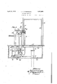
Fig. 1 is a sectional elevation taken on the vertical 'center line of the fluid reservoir and through `the elevator lpit and disclosing diagrammaticallythe remote control for the device. l
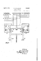
' Fig. 2 is an enlarged diagrammatic view showing a typical form of control.
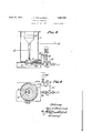
Fig. 3 is` a sectional elevation of the reservoir and associated mechanism; and Fig. 4 is a sectional plan taken on the line IV-IV of Fig-3; 'these latter views being 50 on substantially twice the scale of Fig. 1, and
on reference` to` the accompanying drawings,
showing a modification of the arrangement of the parts.
Referring now to the drawings in which the various parts are indicated by numerals,
10 ,is an elevator pit in which the upper end 55 11 of a hydraulic elevator cylinder is disposed. This cylinder extends downward below the bottom of the pit to such depth as may be necessary for the particular elevator involved. 12 is a plungerdisposed in this 60 cylinder and 13 a superstructure secured thereto. 14 is the lioor of an elevator which floor is supported by the super-structure 13.
15 indicates the side walls of the elevator cage. 16 are posts or guides for the elevator 65 which may be used should it be so desired.
17 is a tank or reservoir for the liquid, ordinarily oil, which is sed in raising the plunger of the elevator. Mounted within the tank is an electric motor 18, which is directly connected to a pump 19 from which a discharge pipe 20 leads to the cylinder 11. 21 is astrainer covered inlet to the pump 19. 22 is a check valve in the discharge pipe 20, preventing return flow therethroughto the pump. 23 is a by-pass line leading from the line 20 between the check valve 22 and the cylinder back into the tank 17. 24; is a normally closed release valve disposed in the bypass line and 25 a solenoid for opening and $0 closing this valve. 26 is a shock absorber for absorbing water-hammer in the pipe line 23.
In Figs. 3 and 4 the valve 24 is positionedl about level with the bottom of the reservoir 17, and the tail pipe 23A, leadingtherefrom l is carried into the reservoir so that it will rest on the bottomthereof, so that at all times such pipe will bevfull. Preferably also this pipe lis continued within the reservoir in a 90 coil 23B so thatk additional inertia will be. set up in such by-pass line. In this modiicaf tion, the pump inlet is preferably carried definiteiy above the level of the tail pipe 23A.
27 is a motor starter, 28 a solenoid starter 95 and 29 are push button panels, two of which are shown in Fig. 1, and three in Fig. 2. Each of these panels has three control but.- tons. Thev first of these buttons 30, is used tostart the motor 18 and raise the elevator.. 10
The second button 31 is used to stop the elevator, either goingup or down, and the third button 32 to lower the elevator. These buttons ordinarily carry designations such as Up, Stop, and Down, respectively, to indicate their use for such purposes. These bute tons are connected by suitable wiring with the motor starter and solenoid starter. Where a control is carried on the elevator the connectionv is by flexible insulated wires, which ordinarily are collected into a flexible cable 33.
In Fig. 2, I have shown diagrammatically a typical layout by which this control may be accomplished. Referring now to that drawing a pair of wires- 34 leads from the button 30 to switch actuating means, shown as a magnet 35, which magnet when energized by this circuit closes the switch 36 and starts the motor 18, these circuit wires also lead through a second magnet 37 in the solenoid box 38, which magnet 37 when energized opens the switch 39 which actuates the solenoid 25 so that when the lbutton 30 is pushed to start the motor the solenoid controlled valve is also closed.
A second pair of wires 40 leads from the stop button 31 to the magnet 37 which accomplishes opening of the solenoid switch and to a magnet 41 which when energized opens the motor switch 36 thereby cutting 0E the motor, so that pushing the stop button at one and the same time, shuts oi the motor and closes the solenoid switch.
A third pair ot wires 42 leads from the down button 32 to a third magnet 43 which when energized closes the switch 39 and energizes the solenoid 25 to open the solenoid control valve 24. These'eircuit wires also lead to the magnet 41 which opens the motor switch 36 whereby the motor circuit is broken at the same time that the solenoid circuit is actuated. l
- It will be notedthat the buttons on the panels may be used interchangeably so that a cycle of control may be accomplished from one panel or from two or even more panels as may be desired.
It will be understood that the various units herein shown may be largely purchased in the open market so that the detail thereof need not herebe shown.
It will be seen that I have combined into a self-contained unit the tank which serves as a reservoir for the lifting unit, the pump which transfers this liquid to the cylinder, the check valve which prevents return iow throu h the pump discharge pipe, the by- 'ne and the release valve therefor,
PISS which rmits accomplishment of the return vflow through the tank, and by the use of remote controls have accomplished the utilization of -such a unit and its control from such remote points.
It will further be noted that the pump and motor in the present case are preferably of high speed type, which types are inherently more or less noisy and that by mounting and enclosing the motor within the tank and the pump in direct contact and partially submerged in the liquid within the tank, that such liquid serves to deaden and greatly reduce if not to eliminate the noise incident to such operation.
It will be further noted as disclosed in 3 and 4, that in bringing the tail line Figs. 23 leading from the Control valve 24 into the bottom of the reservoir, and extending it to some length that I am able to maintain a considerable amount of oil in this line adjacent the control valve and that by keeping this line full of oil, inertia and back pressure due to friction in the pipe minimize the sudden drop which occurs, and which however small, is incident to the ordinary o era tion of hydraulic elevators, and that eeping the pipe full of oil also prevents the formation of air pockets therein, which pockets cause slight but nevertheless unpleasant jars when the control valve is first opened.
Having described :my invention, what I claim is:
1. A hydraulic elevator operating unit comprising a reservoir for the liquid, a pump and a motor associated therewith, a hydraulic connection from said pump to the cylinder of said elevator, valve controlled means for allowing' return How from said hydraulic connection to said reservoir, said means comprising a pipe of substantial length having its discharge end terminating in a horizontal coil, said coil havin a plurality of turns of decreasing radii an being disposed 4within t-he reservoir, and said pump having its intake lopening abovethe level of said coil, whereby submergence thereof is maintained.
2. A hydraulic elevator operating unit comprising a reservoir for the liquid, a pump and a motor associated therewith, a hydraulic connection from said pump to the cylinder `of said elevator, a cheek valve in said connection preventing return flow through said pump, valve controlled means for allowing return flow from said elevator to saidV reservoir, said means comprising a pipe of subf stantial length having a discharge end terminating -i-n a horizontal coil, said coil having a plurality of turns of decreasing radii and being disposed within the reservoir, and said pump having its intake opening above the level of said coil, whereby submergence thereof is maintained.
In testimony whereof I hereunto aflix my signature.
LOUIS C. l STUKENBORG.
Priority Applications (1)
| Application Number | Priority Date | Filing Date | Title |
|---|---|---|---|
| US495069A US1853096A (en) | 1930-11-12 | 1930-11-12 | Hydraulic elevator |
Applications Claiming Priority (1)
| Application Number | Priority Date | Filing Date | Title |
|---|---|---|---|
| US495069A US1853096A (en) | 1930-11-12 | 1930-11-12 | Hydraulic elevator |
Publications (1)
| Publication Number | Publication Date |
|---|---|
| US1853096A true US1853096A (en) | 1932-04-12 |
Family
ID=23967138
Family Applications (1)
| Application Number | Title | Priority Date | Filing Date |
|---|---|---|---|
| US495069A Expired - Lifetime US1853096A (en) | 1930-11-12 | 1930-11-12 | Hydraulic elevator |
Country Status (1)
| Country | Link |
|---|---|
| US (1) | US1853096A (en) |
Cited By (3)
| Publication number | Priority date | Publication date | Assignee | Title |
|---|---|---|---|---|
| US3004812A (en) * | 1958-04-16 | 1961-10-17 | Richard A Miller | Fluid operator mechanism and control assembly therefor |
| US3132631A (en) * | 1961-03-28 | 1964-05-12 | Holman | Automatic boiler blowdown |
| US3230714A (en) * | 1963-12-26 | 1966-01-25 | Emil J Paidar Company | Power operated chair with fluid brake |
-
1930
- 1930-11-12 US US495069A patent/US1853096A/en not_active Expired - Lifetime
Cited By (3)
| Publication number | Priority date | Publication date | Assignee | Title |
|---|---|---|---|---|
| US3004812A (en) * | 1958-04-16 | 1961-10-17 | Richard A Miller | Fluid operator mechanism and control assembly therefor |
| US3132631A (en) * | 1961-03-28 | 1964-05-12 | Holman | Automatic boiler blowdown |
| US3230714A (en) * | 1963-12-26 | 1966-01-25 | Emil J Paidar Company | Power operated chair with fluid brake |
Similar Documents
| Publication | Publication Date | Title |
|---|---|---|
| US1867602A (en) | Fueling system | |
| US1853096A (en) | Hydraulic elevator | |
| US1738809A (en) | Steam trap | |
| ES341092A1 (en) | Automatic emergency relevelling device for lifts | |
| US2295948A (en) | Valve | |
| US2457863A (en) | Air charger | |
| CN208732395U (en) | Fluid pressure type home lift | |
| US3757701A (en) | Emergency mine elevator | |
| GB416781A (en) | Improvements in or relating to lifts | |
| US1925474A (en) | Winch, especially for use in granaries | |
| US1669184A (en) | Elevator | |
| GB1248417A (en) | Improvements in or relating to electric lifts | |
| US1268109A (en) | Elevator-controlling system. | |
| US1203323A (en) | Elevator-actuating mechanism. | |
| US3123036A (en) | Ship salvage equipment | |
| US2218051A (en) | Windmill control | |
| US900669A (en) | Pumping mechanism. | |
| US1907442A (en) | Hydraulic power shovel | |
| US1903763A (en) | Hydraulic lifting mechanism | |
| US3253679A (en) | Hydraulic elevator leveling system | |
| US1976519A (en) | Fuel pump | |
| JPS58183581A (en) | Hydraulic elevator | |
| US1515195A (en) | Submarine mine | |
| JPS61130190A (en) | Floor aligner for elevator | |
| US1833827A (en) | Method and apparatus for deep well pumping |