US1853063A - Machine for applying labels to cylindrical cans or the like - Google Patents
Machine for applying labels to cylindrical cans or the like Download PDFInfo
- Publication number
- US1853063A US1853063A US337673A US33767329A US1853063A US 1853063 A US1853063 A US 1853063A US 337673 A US337673 A US 337673A US 33767329 A US33767329 A US 33767329A US 1853063 A US1853063 A US 1853063A
- Authority
- US
- United States
- Prior art keywords
- paste
- machine
- label
- cans
- tracks
- Prior art date
- Legal status (The legal status is an assumption and is not a legal conclusion. Google has not performed a legal analysis and makes no representation as to the accuracy of the status listed.)
- Expired - Lifetime
Links
Images

Classifications
-
- B—PERFORMING OPERATIONS; TRANSPORTING
- B65—CONVEYING; PACKING; STORING; HANDLING THIN OR FILAMENTARY MATERIAL
- B65C—LABELLING OR TAGGING MACHINES, APPARATUS, OR PROCESSES
- B65C3/00—Labelling other than flat surfaces
- B65C3/06—Affixing labels to short rigid containers
- B65C3/08—Affixing labels to short rigid containers to container bodies
- B65C3/10—Affixing labels to short rigid containers to container bodies the container being positioned for labelling with its centre-line horizontal
- B65C3/12—Affixing labels to short rigid containers to container bodies the container being positioned for labelling with its centre-line horizontal by rolling the labels onto cylindrical containers, e.g. bottles
Definitions
- This invention l relates to y improvements. in
- the invention pertains to improvements in ⁇ labelling machines of the typein which the cans,rWh ile rolling along as thefcans travel along the tracks.
- One of the objects of the invention is to proby the travelling cans for depositing the adhesive-in various amounts to the labels, yand' preferably to the trailing ends of the-latter.
- a further Object is to furnish means of this character, including ya novel valved perforated paste bar arranged to yieldinglyengage the uppermost labell of a stack for neatly applying ⁇ adhesive* to the labels. ⁇ Y
- Another object is to provide a machine of this type,.including an elevator forl the pile of labels; suchelevator being moved step by as they travel through the machine.
- Avstill further object is to providesuch aV machine witha novel kcan .actuated paste roll', so ⁇ designed as to evenly apply spots of adhesiveto theperipheries of the travelling cans, even thoughv such adhering foreign substances, such as parts of the substance which the cans contain.
- Figil is a perspective viewof the machine
- Fig. 4 is a transverse sectional view on the line 4.-4 of Fig. ⁇ 3.
- Fig. 5 is a similar viewon theS-line' of Fig. 3.
- Fig. 6 isa longitudinal horizontal sectional 50 view of the machine. -f
- yFig.- 7' is a longitudinal. vertical sectional View of the valved paste kdistributing bar.
- Fig. 8 is anenlarged bottomplan view of the medial portion of the latterpk 'g Y 55
- Fig. 9 is ayvertical sectional vieiv'of the bar on line 9 9 of Fig-,8.
- Fig. 11 is an elevation, partly invertical section of the ratchet fand pawl mechanism employed to drive the paste distributing pump,.etc. l A f ,Fig. 11 is adevelopedvperspective view ofthe y.parts of one of the rollersand bellcrank. leversemployed yin ldriving certain ⁇ parts Lby the cans as they roll over the tracks.
- Fig. 12 is/-a vertical sectional view ofthe elevator operating means.
- y ⁇ y y Fig. 13 is an elevation partly in section of meansfor actuating the elevator manually, and
- Fig. 14 is an elevation of a fragment of the mechanism, shown in Fig. 13. n
- AIn thedrawings, 11 indicates a tablesupf ported by legsg12. ⁇
- the table carries the frame 13 which supports certain parts of my improved mechanism.
- Y l, Posts 14, at the ends of the frame, carry f axles 15, 16 to which guide pulleys v17are fixed. From Fig. 1, it Will be observed that the shaft 16 has a projectingportion A on which a driving gear 18 (Fig. 2) may be mounted for imparting movement to various movable parts of the machine.
- a rotary sepf arator -19 is carried bybrackets-,20 on the feeding tracks 21, and this separator isdriven bv a belt 22 from a pulley 23 onthe shaft 16.
- -- rlhe separator is of lconventional construcf tion, and simply acts to-space .the -cans as they kroll one after the other incontacting relation down the tracks v21 on to the tracks y engaged by a spring pressed pawl ally 24 at the eeding end of the frame of the machine.
- the cans are positively rolled through the machine by means of belts 25 which are mounted on the pulleys 17 and are pressed at their lower sides toward the table 12 by conventional pressure rollers 26, each ot' which is mounted on a pivoted arm 27, carried by a post 28; the roller on the arm being pressed downwardly, for example, by screws 29.
- a can 30 is shown in the act of rolling along the tracks 24, and its periphery is in contact with a positively dr1ven paste roller 31, which is of special design, This roller,
- the paste roller is provided with spaced series of circumferential teeth 32, and the teeth of each series are separated by notches 33, so that when a line of these teeth extending lengthwise of the roller, comes in contact with the periphery of the can, a number of spots of adhesive will be deposited on the can.
- the paste roller is partially submerged in a paste pan or trough 34, which has apertured ears engagin suspension screws 36.
- the paste roller is fast on a shaft 38, journaled in brackets 39 in the pan, and having an extension 39 projecting through one end of the pan.
- This shaft is intermittently operated by a pawl and ratchet mechanism, actuated by the cans, as they tra-vel along the tracks 24.
- pawl and ratchet mechanism may be of the type detailed in Figs. 10 and 11.
- the shaft of the paste roll may be provided with a fixed ratchet wheel 4() that is 41, pivotmounted on a lever 42 which oscillates on the shaft.
- a link 43 connects this lever to one arm 44 of a bell-crank lever which is pivotally mounted on a post 45 that is carried the frame, and positioned above one of the tracks 24.
- the other arm 46 of the bell crank carries a roller 47 which engages one of the belts 25. From this explanation it will be understood that as each can rolls along the tracks 24, it raises the roller 47,
- the can or the like, with a line of paste spots applied thereto reaches the end 48 of thel tracks 24, (Fig. 3), it comes in contact with the uppermost label of a pile 49, carried by an elevator platform ⁇ 50.
- This platform is shown in lowered position in full lines, and in upper position in dotted lines.
- the can after leaving the tracks 24, rolls over the highest end of the uppermost label.I and t-he parts are properly spaced so that the spots of glue on the can adhere to this label, and consequently, as the can rolls forwardly over intermediate tracks 51, the label is automatically wrapped around the can.
- the spots of paste on the can supply the adhesive for one end of the label, and that a aste bar 52 applies adhesive to the other end of the label.
- the tracks 51 are arranged at the medial portion of the frame, and their upper edges are of substantially arc-shape, as shown at 53, so that the can in rolling along the intermediate portion of the frame, is slightly elevated in order to permit the label to wrap around the same without interference.
- the upper surface ot' the platform 5() is inclined downwardly toward the delivery end of the machine, whereby, While the can is rolling over the tracks 53, the label will wrap around the can until it reaches a point where it pulls the pasted trailing end of the label from beneath the paste bar 52.
- the belts 25 assist in wrapping the labels on the cans, and when the cans roll on to the delivery tracks 54, they are pressed against a pad 55, interposed between these tracks, an this causes the label to be smoothed out so that the can, in leaving the delivery end 56 of the tracks 54, will be properly labeled.
- Such means includes a pair of leaf springs 57, each of which is secured at its upper end to brackets or blocks 58, carried by the frame. These springs are arranged at opposite sides of the frame, and they curve. rearwardly and downwardly to the paste bar 52 which they support. For the purpose of pressing this bar downwardly in contact with the labels carried by the elevator, screws 59 may be used. Each of these screws engages al stationary nut 60 on the frame, and its lower end ilnpinges against the spring 57 with which it cooperates.
- the paste bar 52 is formed of upper and lower flat strips 61 and 62, which are detachably connected together by any suitable means.
- Each strip has a semi-cylindrical longitudinally extending recess 64 to provide a cylindrical passageway lengthwise of the bar.
- I extend a rotatlill) Y ⁇ tary 'feed a multiplicity of streams the face of each label. from-the ports 70 to one edge ofthefacing y f'plate, and provide means for preventing the paste from ⁇ spreading fromthe paste spots on 'thela-behas the latter is Withdrawn from "able-tube' 65,'having a series of apertures 66 which cooperate with ports 67 inl the bar, to
- the latter may be provided at one tube 65, and the quantity delivered therefrom 't0 the labels is automatically controlled by Q rlhe delivery pipe 76- of'this pumpdischarges aan vthat oscillates on the shaft.
- thepump shaftSOl may have a fixed ratchet wheel '81, driven by a paivl 82,carried by a lever 83 rlhis lever 3) is connected by a link 84 to a bell-crank lever 85 that is pivotally mounted at 86 on a'bracket, carriedfbythe frame.
- Each ofthe levers 83 and 85 is provided With a plurality of holes 83a'to receive pins Twhich adjust ably connect the link .84 to said levers.
- a roller 87 onthe bell-,crank lever is pre ed upwardlyby each can; as the latter travels alongthe.delivery'traclrs 54, and ofcourse, this causes actuation of the lpumpin a manofpaste from with suitable valves, and kits piston 97 ⁇ ner which will be' apparent to those skilled in the art. ⁇
- the latter lis pivotally mounted in the frame and is loperatively connected to a link 99 which extends through a slot 100in the table 11, and is joined at its upper end to a bell- Crank lever ⁇ 101.
- a link 99 which extends through a slot 100in the table 11, and is joined at its upper end to a bell- Crank lever ⁇ 101.
- This lever ispivotally mounted on a'braclet 102, and tcarries a vroller 103 that 'bears against one of the belts whereby each time a can rolls beneath the roller 103, the latter Will be raised to actuate the bell-crank lever'101, and thisfmovement will be. imparted by the link 99, to theV pump lever 98, so that the pump 94 will raise Y the platform 50 step by step.
- the present invention in-k cludes novel elevating means.
- f As best shown win Figs.-l 3 and 4,y such means comprises a pisyton rod 88thart depends from theplatform .50, intov a v,cylinder 89, suspended from the vtable 11. The lower end of the rod 88 is pro- ⁇ When this valve is opened, a spring 106,
- f spots of adhesive will be applied along a line lengthwise of the periphery of each can, and should any foreign substance, such as grains of corn, peas or the like be adhering to the surface of the can, and be transferred to the paste roller, the spaces and notches in the latter will receive such foreign substance,V
- the can After the can has been provided with the paste spots, it continues to roll forward under the influence of the belts 25, and as the guide rollers which are engaging the belts above the tracks 24, are arranged on inclines, as shown in Fig. 5, the belts will only engage the edges of the can, and consequently, the paste spots will not be disturbed.
- a machine for applying labels to cans or the like means for supporting a label, a paste distributor adapted to apply paste to the label, and means for causing the paste to move in an endless stream relatively to said distributor.
- a label support for applying labels to cans or the like, a label support, a paste distributor for applying paste to a label carried by the support, means for moving fluid paste in an endless stream through said distributor, and means for varying the amount of paste delivered by the distributor to the label.
- a paste distributor including a bar having a passageway and provided at one side with a paste outlet means, a facing plate secured to the bar and having paste outlet means cooperating with the paste outlet means of the bar, said facing plate having outwardly diverging edge portions for guiding labels into position against the facing pla-te, and means for feeding fluid paste into said passageway.
- a label support adapted to apply paste to a label while the latter rests on the support, said distributor including a housing provided with paste I outlet means, a paste reservoir, means for feeding paste from the reservoir into the housing, and means for returning excess paste from the housing to the reservoir.
- a label support a paste distributing bar extending across the support and adapted to apply paste to a label carried by the support, said bar having a passageway extending therethrough, and delivery ports communicating with the passageway, a rotatable tube extending through said passageway and having apertures cooperating with the ports for delivering the paste, a supply reservoir, means for feeding paste from the reservoir to the tube, and means for returning paste from the tube to the reservoir.
- a label support and means for distributing paste on to a label carried by said support, said means including a plate having a series of delivery ports and grooves communicating with said ports.
- a label support In a machine for applying labels to cans or the like, a label support, a paste distributing bar arranged to apply paste to a label carried by the support, resilient means for supporting said bar, and means for furnishing paste to said bar.
- a label support a paste distributor cooperating therewith for applying paste to a label while it is carried by said support, means including a pump for delivering paste to said paste distributor, a can runway, a member projecting into the path of movement of cans travelling along the runway, and
- a runway for articles to be labeled a label elevator, hydraulic means for actuatingthe elevator, and operating means for the elevator, including a part projecting intothe path kof movement of the articles, whereby movement of the articles along the runway vwill cause the elevator to actuate.
- a label support and a paste distributor adapted to apply paste to a label carried by the support, said distributor including a ila-t casing formed of upper and lower plates, each plate being grooved and the grooves forming a bore, the lower'one of the plates being provided with spaced apertures communicating with said bore, a tube movably mounted in said bore and having paste outlet means cooperating with'said apertures,
- Vand means for delivering paste to said tube.
- a label elevator including a platform, a piston operatively connectedto the platform, a cylinder for the piston, a reservoir for a liquid, means for pumping liquid.
- trolled means to permit liquid ⁇ to flow from the cylinder into the reservoir when the platform is to be lowered.
Description
A. H. KYLER April 12, 1.932.,
MACHINE FOR APPLYING LABELS TO CYLIlJDFICAL CANS OR THE LIKE Filed Feb, 5, 1929 4 Sheets-Shee(l mm 9 om tu April 12, 1932. A, H, KYLER `1,853,063
MACHINE FOR APPLYING LABELS TO` CYLINDRICAL CANS OR THE LIKE April 12, 1932. A. H. KYLER 1,853,063
MACHINE FOR APPLYING LABELS TO CYLINDRICAL CANS OR THE LIKE Filed Feb. 5, 1929 4 sheets-sheet 5 April 12, 1932.. A. H. KYLER 1,853,063
MACHINE FOR- APPLYING LABELS TO CYLINDRICAL CANS OR THE LIKE Filed Feb. 5, 1929 4 sheets-sheet 4 .suitable tracks, pick up labelsthrough the mediumof an adhesive, and apply the labels vide novel means including a pump actuated f step upwardly, by means actuated by thecans f if) Patented Apr. 12,: 1932 ALBERT H. kinnen." or WEsTMrNsTEa, MARYLAND f MAGHINE ron APPLYINGLABELS TocYLINnRIcALcANs on THE LIKE Application 'filed February 5,` 1929. Serial 1\To: x33 '1,6737.l
This invention lrelates to y improvements. in
machines for applying labels to ycylindrical cans or the like. y
-More specifically, the invention pertains to improvements in` labelling machines of the typein which the cans,rWh ile rolling along as thefcans travel along the tracks.
One of the objects of the invention is to proby the travelling cans for depositing the adhesive-in various amounts to the labels, yand' preferably to the trailing ends of the-latter. A further Objectis to furnish means of this character, including ya novel valved perforated paste bar arranged to yieldinglyengage the uppermost labell of a stack for neatly applying `adhesive* to the labels.` Y
Another object is to provide a machine of this type,.including an elevator forl the pile of labels; suchelevator being moved step by as they travel through the machine.
. Avstill further object is to providesuch aV machine witha novel kcan .actuated paste roll', so` designed as to evenly apply spots of adhesiveto theperipheries of the travelling cans, even thoughv such adhering foreign substances, such as parts of the substance which the cans contain.
With the foregoing objects outlined and with other objects in view which will appear as the description proceeds, the invention consists inl the novel features hereinafter described in det-ail, illustrated in the accompanying drawings, and more particularly pointed'out in the appendedv claims. f,
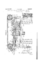
y Referringto the drawings, Figil isa perspective viewof the machine,
looking fromone side thereof. n
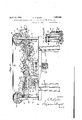
2 isr a similar view as seen `from the opposite side.' ,f Fig.,3 is a longitudinal verticalsectional view pf the same.
peripheries should carry.
'.Fig. 4 is a transverse sectional view on the line 4.-4 of Fig. `3. s s s y y Fig. 5 isa similar viewon theS-line' of Fig. 3. n f
Fig. 6 isa longitudinal horizontal sectional 50 view of the machine. -f
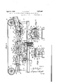
yFig.- 7'is a longitudinal. vertical sectional View of the valved paste kdistributing bar.,
Fig. 8 is anenlarged bottomplan view of the medial portion of the latterpk 'g Y 55 Fig. 9 is ayvertical sectional vieiv'of the bar on line 9 9 of Fig-,8. ,l f j' K Fig.` 10`is an elevation, partly invertical section of the ratchet fand pawl mechanism employed to drive the paste distributing pump,.etc. l A f ,Fig. 11 is adevelopedvperspective view ofthe y.parts of one of the rollersand bellcrank. leversemployed yin ldriving certain` parts Lby the cans as they roll over the tracks.` Fig. 12 is/-a vertical sectional view ofthe elevator operating means.y `y y Fig. 13 is an elevation partly in section of meansfor actuating the elevator manually, and
Fig. 14; is an elevation of a fragment of the mechanism, shown in Fig. 13. n
AIn thedrawings, 11 indicates a tablesupf ported by legsg12.` The table carries the frame 13 which supports certain parts of my improved mechanism. Y l, Posts 14, at the ends of the frame, carry f axles 15, 16 to which guide pulleys v17are fixed. From Fig. 1, it Will be observed that the shaft 16 has a projectingportion A on which a driving gear 18 (Fig. 2) may be mounted for imparting movement to various movable parts of the machine. ,A rotary sepf arator -19 is carried bybrackets-,20 on the feeding tracks 21, and this separator isdriven bv a belt 22 from a pulley 23 onthe shaft 16.-- rlhe separator is of lconventional construcf tion, and simply acts to-space .the -cans as they kroll one after the other incontacting relation down the tracks v21 on to the tracks y engaged by a spring pressed pawl ally 24 at the eeding end of the frame of the machine.
The cans are positively rolled through the machine by means of belts 25 which are mounted on the pulleys 17 and are pressed at their lower sides toward the table 12 by conventional pressure rollers 26, each ot' which is mounted on a pivoted arm 27, carried by a post 28; the roller on the arm being pressed downwardly, for example, by screws 29.
As each can is rolled along the tracks 24, its periphery is provided with series of spots of adhesive which extends longthwise of the can. The means for accomplishing this are best shown in Figs. 3, 5 and 6. In these tigures, a can 30 is shown in the act of rolling along the tracks 24, and its periphery is in contact with a positively dr1ven paste roller 31, which is of special design, This roller,
is provided with spaced series of circumferential teeth 32, and the teeth of each series are separated by notches 33, so that when a line of these teeth extending lengthwise of the roller, comes in contact with the periphery of the can, a number of spots of adhesive will be deposited on the can. To this end, the paste roller is partially submerged in a paste pan or trough 34, which has apertured ears engagin suspension screws 36. The
an is adjustabv supported on these screws Ey thumb nuts 3 and this construction per- ,mits the pan to be raised or lowered.
The paste roller is fast on a shaft 38, journaled in brackets 39 in the pan, and having an extension 39 projecting through one end of the pan. This shaft is intermittently operated by a pawl and ratchet mechanism, actuated by the cans, as they tra-vel along the tracks 24. Such pawl and ratchet mechanism may be of the type detailed in Figs. 10 and 11. For example, as shown in these tigures, the shaft of the paste roll may be provided with a fixed ratchet wheel 4() that is 41, pivotmounted on a lever 42 which oscillates on the shaft. A link 43 connects this lever to one arm 44 of a bell-crank lever which is pivotally mounted on a post 45 that is carried the frame, and positioned above one of the tracks 24. The other arm 46 of the bell crank carries a roller 47 which engages one of the belts 25. From this explanation it will be understood that as each can rolls along the tracks 24, it raises the roller 47,
` thus causing the bellcrank lever 44, 46 to depress the link 43, whereby the pawl 41 moves the ratchet wheel 40 one step and thereby rotates the paste roll one step. As the can moves from beneath the roller 47, the weight of the part-s returns them to normal position, so that the pawl 41 may be properly positioned for the succeeding movement.
lVhen the can or the like, with a line of paste spots applied thereto, reaches the end 48 of thel tracks 24, (Fig. 3), it comes in contact with the uppermost label of a pile 49, carried by an elevator platform` 50. This platform is shown in lowered position in full lines, and in upper position in dotted lines. It will be seen that the can, after leaving the tracks 24, rolls over the highest end of the uppermost label.I and t-he parts are properly spaced so that the spots of glue on the can adhere to this label, and consequently, as the can rolls forwardly over intermediate tracks 51, the label is automatically wrapped around the can. At this point, it may be mentioned that the spots of paste on the can, supply the adhesive for one end of the label, and that a aste bar 52 applies adhesive to the other end of the label.
The tracks 51 are arranged at the medial portion of the frame, and their upper edges are of substantially arc-shape, as shown at 53, so that the can in rolling along the intermediate portion of the frame, is slightly elevated in order to permit the label to wrap around the same without interference. For this same purpose, the upper surface ot' the platform 5() is inclined downwardly toward the delivery end of the machine, whereby, While the can is rolling over the tracks 53, the label will wrap around the can until it reaches a point where it pulls the pasted trailing end of the label from beneath the paste bar 52. Of course, the belts 25 assist in wrapping the labels on the cans, and when the cans roll on to the delivery tracks 54, they are pressed against a pad 55, interposed between these tracks, an this causes the label to be smoothed out so that the can, in leaving the delivery end 56 of the tracks 54, will be properly labeled.
Revertin g now to the medial portion of the machine, I desire to call particular attention to novel means which I have provided for applying a transverse line of paste spots to the upper surface of the trailing or lower end of the labels. Such means includes a pair of leaf springs 57, each of which is secured at its upper end to brackets or blocks 58, carried by the frame. These springs are arranged at opposite sides of the frame, and they curve. rearwardly and downwardly to the paste bar 52 which they support. For the purpose of pressing this bar downwardly in contact with the labels carried by the elevator, screws 59 may be used. Each of these screws engages al stationary nut 60 on the frame, and its lower end ilnpinges against the spring 57 with which it cooperates.
As best shown in Figs. 7 and 9, the paste bar 52 is formed of upper and lower flat strips 61 and 62, which are detachably connected together by any suitable means. Each strip has a semi-cylindrical longitudinally extending recess 64 to provide a cylindrical passageway lengthwise of the bar. Through this passageway, I extend a rotatlill) Y `tary 'feed a multiplicity of streams the face of each label. from-the ports 70 to one edge ofthefacing y f'plate, and provide means for preventing the paste from `spreading fromthe paste spots on 'thela-behas the latter is Withdrawn from "able-tube' 65,'having a series of apertures 66 which cooperate with ports 67 inl the bar, to
the' bar downwardly onv to the .labels onv the elevator. A' facing plate 68 that is secured to- Ithe under side of the bar by means of screws v69, is also provided Withv flared ports 70,
.which constantly registerl with the ports 67 to distribute the paste uniformly in spots across Grooves 71k extend beneath .the bar.` y p yThe registering ports in the tube and `baro?, 'provide means xvhereby the amount of paste. fed to the fportsw ymaybe varied, and
Ain'order to permit the operator to turn the end with La finger Wheel `7 Y Fluldpasteis contmuouslyffed through the tube 65, the latter may be provided at one tube 65, and the quantity delivered therefrom 't0 the labels is automatically controlled by Q rlhe delivery pipe 76- of'this pumpdischarges aan vthat oscillates on the shaft.
into a flexible pipe 7 7k Which carries the paste tothe inlet end of the tube 65 .of the paste ban- Any excess otpaste over: that delivered through the ports'70 is'returned tothe` reservoir73 by ymeans yof aflexible pipe-78 which leads from .the Voutlet end kof the tube 65 to the reservoir. The flexible pipes 77 and 78 permitthe paste bar to rise and fall Without interference. Y Y
` At this point it mightbe noted that the lat- V'eral edges of the facing plate 63 of the paste bar divergeldownwardly, as shown at 79, and
theyfunction in this Way as guides orcon-` fining means forthe lateral edges of the labels (seeFig). f l, Y,
- I prefer to'operate the pump 75 by ratchet and pavvlmechanism similar to that shown in Figs. 10and 11. llorexample,y thepump shaftSOlmay have a fixed ratchet wheel '81, driven by a paivl 82,carried by a lever 83 rlhis lever 3) is connected by a link 84 to a bell-crank lever 85 that is pivotally mounted at 86 on a'bracket, carriedfbythe frame. Each ofthe levers 83 and 85 is provided With a plurality of holes 83a'to receive pins Twhich adjust ably connect the link .84 to said levers. A roller 87 onthe bell-,crank lever, is pre ed upwardlyby each can; as the latter travels alongthe.delivery'traclrs 54, and ofcourse, this causes actuation of the lpumpin a manofpaste from with suitable valves, and kits piston 97 `ner which will be' apparent to those skilled in the art.`
vided with a piston 90 which is raised in the cylinder by placing pressure' on ak hydraulic fluidV suchras oil 91`Which is forced into the lower end of the cylinder.v F or this purpose, thelovv'er end of the cylinder communicates byl aconduit 92, vWith the cylinder 93 of a reciprocatingpiston pump 94;' This pump draws oil through a passageway 95 from a reservoir 96,r and forces the :same through the conduitI 92 into the cylinder forv the purpose yof elevating the platform 50. Of course, the pump 94 is'provided Y is piv- `otally connected to an operating lever 98. The latter lis pivotally mounted in the frame and is loperatively connected to a link 99 which extends through a slot 100in the table 11, and is joined at its upper end to a bell- Crank lever `101. yThis lever ispivotally mounted on a'braclet 102, and tcarries a vroller 103 that 'bears against one of the belts whereby each time a can rolls beneath the roller 103, the latter Will be raised to actuate the bell-crank lever'101, and thisfmovement will be. imparted by the link 99, to theV pump lever 98, so that the pump 94 will raise Y the platform 50 step by step.
In mechanism .of this character, it is dek sirable rto have the platform 50 so combined with yits elevating means that the platform may be immediately lowered Whenever desired.: I therefore place'the interior of the cylinder 89 and reservoir 96 in communica# tion,also by a passageway 10,4, which isr normally closed by a hand operated valve 105.
As beforestated, the present invention in-k cludes novel elevating means. f As best shown win Figs.- l 3 and 4,y such means comprises a pisyton rod 88thart depends from theplatform .50, intov a v,cylinder 89, suspended from the vtable 11. The lower end of the rod 88 is pro- `When this valve is opened, a spring 106,
which' `has lone of its ends connected to the platform -50, yand its other end secured to the bottomr of the reservoir, functions to pull the platform downwardly, and 1n such movef ment, the piston forces the oil from the vchamber 89 into the reservoir 96. f 'As it is also desirable'that the platform 50 be raised to any required height rapidly, Without actuating the sameby means of the roller 103, I-propose to combinethe reservoir 96 with an additional pump 107, (see Figs; 13 and 14), which communicates `by passage- Ways 108 and 109 With the cylinder and reservoir.' lThe piston 110 of thiszpump is provided With a yolre 111 at itsupper end, which receives a stud 112` that is eccenrtrically arranged on a dislr113 that is rotatably mount-` ed, and provided with a handle114. VWhen the handle is turned, the piston of this pump will be rapidly reciprocated, softhat transfer ofliquid from the reservoir 96 to the ycylinder 89 will be expedited, and the platform will be quickly raised.
It is believed that the operation may be readily understood from the foregoing description, but by way of reiteration, it may be stated that the cans coming from the sealing machine, will roll down the tracks 21, and will be properly spaced by the separator 19. Then, as each can rolls over the tracks 24, it will come in contact with the belts 25, and these belts will press the cans downwardly while they contact with the paste roller 31. Owing to the numerous notches and spaces in the periphery of this roller,
f spots of adhesive will be applied along a line lengthwise of the periphery of each can, and should any foreign substance, such as grains of corn, peas or the like be adhering to the surface of the can, and be transferred to the paste roller, the spaces and notches in the latter will receive such foreign substance,V
and prevent the same from interfering with the proper operation of the machine.
After the can has been provided with the paste spots, it continues to roll forward under the influence of the belts 25, and as the guide rollers which are engaging the belts above the tracks 24, are arranged on inclines, as shown in Fig. 5, the belts will only engage the edges of the can, and consequently, the paste spots will not be disturbed.
Immediately the can leaves the tracks 24, its paste spots will adhere to the uppermost label of the pile 49, and as the can continues to move forwardly over the medial tracks 53, under the influence of the belts 25, .it will automatically wrap the label to which it is adhering, around itself, and just before leaving the tracks 53, it will pull the trailingend ofthelabel from beneath the resiliently supported paste bar 52, and the trailing end of the label will have a line of paste spots which it has rcceived from said bar. Consequently, as the can rolls on to t-he pad 55, the label will be caused to adhere to the can, and will be smoothed out before the can is delivered at the end 56 of the tracks 54.
Of course, as each can travels through the machine, it will actuate the described mechanism for causing intermittent movement of the paste roller 3l, the pump 75, and the elevator 50.
From the foregoing, it is believed that the construction, operation and advantages of the invention may be readily understood, and I am aware that various changes may be made in the details disclosed, without departing from the spirit of the invention, as expressed in the claims.
What I claim and desire to secure by Letters Patent is:
1. In a machine for applying labels to cans or the like, means for supporting a label, a paste distributor adapted to apply paste to the label, and means for causing the paste to move in an endless stream relatively to said distributor.
2. In a machine for applying labels to cans or the like, a label support, a paste distributor for applying paste to a label carried by the support, means for moving fluid paste in an endless stream through said distributor, and means for varying the amount of paste delivered by the distributor to the label.
3. In a machine for applying labels to cans or the like, a paste distributor including a bar having a passageway and provided at one side with a paste outlet means, a facing plate secured to the bar and having paste outlet means cooperating with the paste outlet means of the bar, said facing plate having outwardly diverging edge portions for guiding labels into position against the facing pla-te, and means for feeding fluid paste into said passageway.
4. In a machine for applying labels to cans or the like, a label support, a paste distributor adapted to apply paste to a label while the latter rests on the support, said distributor including a housing provided with paste I outlet means, a paste reservoir, means for feeding paste from the reservoir into the housing, and means for returning excess paste from the housing to the reservoir.
5. In a machine for applying labels to can! or the like, a label support, a paste distributing bar extending across the support and adapted to apply paste to a label carried by the support, said bar having a passageway extending therethrough, and delivery ports communicating with the passageway, a rotatable tube extending through said passageway and having apertures cooperating with the ports for delivering the paste, a supply reservoir, means for feeding paste from the reservoir to the tube, and means for returning paste from the tube to the reservoir.
6. In a machine for applying labels to cans or the like, a label support, and means for distributing paste on to a label carried by said support, said means including a plate having a series of delivery ports and grooves communicating with said ports.
7. In a machine for applying labels to cans or the like, a label support, a paste distributing bar arranged to apply paste to a label carried by the support, resilient means for supporting said bar, and means for furnishing paste to said bar.
8. In mechanism as claimed in claim 7, means for adjusting the bar toward or away from the label support.
9. In a machine for applying labels to cans or the like, a label support, a paste distributor cooperating therewith for applying paste to a label while it is carried by said support, means including a pump for delivering paste to said paste distributor, a can runway, a member projecting into the path of movement of cans travelling along the runway, and
means including ratchet and pawl mecha'-k nismfor operatingl the pump by said member. l0. In a machine of the character described,
a runway for articles to be labeled, a label elevator, hydraulic means for actuatingthe elevator, and operating means for the elevator, including a part projecting intothe path kof movement of the articles, whereby movement of the articles along the runway vwill cause the elevator to actuate. f
rl1. In a machine for applying labels to cans or the like, a label support, and a paste distributor adapted to apply paste to a label carried by the support, said distributor including a ila-t casing formed of upper and lower plates, each plate being grooved and the grooves forming a bore, the lower'one of the plates being provided with spaced apertures communicating with said bore, a tube movably mounted in said bore and having paste outlet means cooperating with'said apertures,
Vand means for delivering paste to said tube.
l2. In afmachine for applyinglabels to cans or the like, a label elevator including a platform, a piston operatively connectedto the platform, a cylinder for the piston, a reservoir for a liquid, means for pumping liquid.
trolled means to permit liquid` to flow from the cylinder into the reservoir when the platform is to be lowered.
In testimony whereof kI have signed this specilication.
ALBERT H., KYLER.
Priority Applications (1)
| Application Number | Priority Date | Filing Date | Title |
|---|---|---|---|
| US337673A US1853063A (en) | 1929-02-05 | 1929-02-05 | Machine for applying labels to cylindrical cans or the like |
Applications Claiming Priority (1)
| Application Number | Priority Date | Filing Date | Title |
|---|---|---|---|
| US337673A US1853063A (en) | 1929-02-05 | 1929-02-05 | Machine for applying labels to cylindrical cans or the like |
Publications (1)
| Publication Number | Publication Date |
|---|---|
| US1853063A true US1853063A (en) | 1932-04-12 |
Family
ID=23321522
Family Applications (1)
| Application Number | Title | Priority Date | Filing Date |
|---|---|---|---|
| US337673A Expired - Lifetime US1853063A (en) | 1929-02-05 | 1929-02-05 | Machine for applying labels to cylindrical cans or the like |
Country Status (1)
| Country | Link |
|---|---|
| US (1) | US1853063A (en) |
-
1929
- 1929-02-05 US US337673A patent/US1853063A/en not_active Expired - Lifetime
Similar Documents
| Publication | Publication Date | Title |
|---|---|---|
| US2192833A (en) | Labeling machine | |
| US1868283A (en) | Sheet reversing device for gumming machines | |
| US1853063A (en) | Machine for applying labels to cylindrical cans or the like | |
| US2234017A (en) | Mechanism for cutting and applying tape to filled bags | |
| US2859727A (en) | Gluing device for box forming machines | |
| US2748971A (en) | Box head labeler | |
| US3045643A (en) | Adhesive applicator for a can labeling machine | |
| US2313643A (en) | Packaging machine | |
| US1410845A (en) | Apparatus for labeling, wrapping, or the like | |
| US1937476A (en) | Labeling machine | |
| US1877042A (en) | Machine for and method of banding packages | |
| US3017311A (en) | Adhesive applicator for a can labeling machine | |
| US2171085A (en) | Labeling machine for bottles and the like | |
| US1085888A (en) | Pamphlet-coverer. | |
| US2682207A (en) | Machine for making and assembling spools | |
| US2246126A (en) | Applicator | |
| US1018398A (en) | Can-labeling machine. | |
| US1344426A (en) | Labeling-machine | |
| US1206345A (en) | Addressing-machine. | |
| US1854245A (en) | Machine for coating cans | |
| US3560303A (en) | Labelling machine for cylindrical containers | |
| US1304943A (en) | Machine fob | |
| US506095A (en) | Can-labeling machine | |
| US1096309A (en) | Envelop-sealing machine. | |
| US1561600A (en) | Can-labeling machine |