US1853058A - Automobile - Google Patents
Automobile Download PDFInfo
- Publication number
- US1853058A US1853058A US513164A US51316431A US1853058A US 1853058 A US1853058 A US 1853058A US 513164 A US513164 A US 513164A US 51316431 A US51316431 A US 51316431A US 1853058 A US1853058 A US 1853058A
- Authority
- US
- United States
- Prior art keywords
- shaft
- wheels
- driving
- automobile
- engine
- Prior art date
- Legal status (The legal status is an assumption and is not a legal conclusion. Google has not performed a legal analysis and makes no representation as to the accuracy of the status listed.)
- Expired - Lifetime
Links
Images

Classifications
-
- B—PERFORMING OPERATIONS; TRANSPORTING
- B60—VEHICLES IN GENERAL
- B60K—ARRANGEMENT OR MOUNTING OF PROPULSION UNITS OR OF TRANSMISSIONS IN VEHICLES; ARRANGEMENT OR MOUNTING OF PLURAL DIVERSE PRIME-MOVERS IN VEHICLES; AUXILIARY DRIVES FOR VEHICLES; INSTRUMENTATION OR DASHBOARDS FOR VEHICLES; ARRANGEMENTS IN CONNECTION WITH COOLING, AIR INTAKE, GAS EXHAUST OR FUEL SUPPLY OF PROPULSION UNITS IN VEHICLES
- B60K6/00—Arrangement or mounting of plural diverse prime-movers for mutual or common propulsion, e.g. hybrid propulsion systems comprising electric motors and internal combustion engines
- B60K6/20—Arrangement or mounting of plural diverse prime-movers for mutual or common propulsion, e.g. hybrid propulsion systems comprising electric motors and internal combustion engines the prime-movers consisting of electric motors and internal combustion engines, e.g. HEVs
- B60K6/22—Arrangement or mounting of plural diverse prime-movers for mutual or common propulsion, e.g. hybrid propulsion systems comprising electric motors and internal combustion engines the prime-movers consisting of electric motors and internal combustion engines, e.g. HEVs characterised by apparatus, components or means specially adapted for HEVs
- B60K6/24—Arrangement or mounting of plural diverse prime-movers for mutual or common propulsion, e.g. hybrid propulsion systems comprising electric motors and internal combustion engines the prime-movers consisting of electric motors and internal combustion engines, e.g. HEVs characterised by apparatus, components or means specially adapted for HEVs characterised by the combustion engines
-
- B—PERFORMING OPERATIONS; TRANSPORTING
- B60—VEHICLES IN GENERAL
- B60K—ARRANGEMENT OR MOUNTING OF PROPULSION UNITS OR OF TRANSMISSIONS IN VEHICLES; ARRANGEMENT OR MOUNTING OF PLURAL DIVERSE PRIME-MOVERS IN VEHICLES; AUXILIARY DRIVES FOR VEHICLES; INSTRUMENTATION OR DASHBOARDS FOR VEHICLES; ARRANGEMENTS IN CONNECTION WITH COOLING, AIR INTAKE, GAS EXHAUST OR FUEL SUPPLY OF PROPULSION UNITS IN VEHICLES
- B60K17/00—Arrangement or mounting of transmissions in vehicles
- B60K17/04—Arrangement or mounting of transmissions in vehicles characterised by arrangement, location or kind of gearing
- B60K17/12—Arrangement or mounting of transmissions in vehicles characterised by arrangement, location or kind of gearing of electric gearing
-
- B—PERFORMING OPERATIONS; TRANSPORTING
- B60—VEHICLES IN GENERAL
- B60K—ARRANGEMENT OR MOUNTING OF PROPULSION UNITS OR OF TRANSMISSIONS IN VEHICLES; ARRANGEMENT OR MOUNTING OF PLURAL DIVERSE PRIME-MOVERS IN VEHICLES; AUXILIARY DRIVES FOR VEHICLES; INSTRUMENTATION OR DASHBOARDS FOR VEHICLES; ARRANGEMENTS IN CONNECTION WITH COOLING, AIR INTAKE, GAS EXHAUST OR FUEL SUPPLY OF PROPULSION UNITS IN VEHICLES
- B60K6/00—Arrangement or mounting of plural diverse prime-movers for mutual or common propulsion, e.g. hybrid propulsion systems comprising electric motors and internal combustion engines
- B60K6/20—Arrangement or mounting of plural diverse prime-movers for mutual or common propulsion, e.g. hybrid propulsion systems comprising electric motors and internal combustion engines the prime-movers consisting of electric motors and internal combustion engines, e.g. HEVs
- B60K6/22—Arrangement or mounting of plural diverse prime-movers for mutual or common propulsion, e.g. hybrid propulsion systems comprising electric motors and internal combustion engines the prime-movers consisting of electric motors and internal combustion engines, e.g. HEVs characterised by apparatus, components or means specially adapted for HEVs
- B60K6/26—Arrangement or mounting of plural diverse prime-movers for mutual or common propulsion, e.g. hybrid propulsion systems comprising electric motors and internal combustion engines the prime-movers consisting of electric motors and internal combustion engines, e.g. HEVs characterised by apparatus, components or means specially adapted for HEVs characterised by the motors or the generators
-
- B—PERFORMING OPERATIONS; TRANSPORTING
- B60—VEHICLES IN GENERAL
- B60K—ARRANGEMENT OR MOUNTING OF PROPULSION UNITS OR OF TRANSMISSIONS IN VEHICLES; ARRANGEMENT OR MOUNTING OF PLURAL DIVERSE PRIME-MOVERS IN VEHICLES; AUXILIARY DRIVES FOR VEHICLES; INSTRUMENTATION OR DASHBOARDS FOR VEHICLES; ARRANGEMENTS IN CONNECTION WITH COOLING, AIR INTAKE, GAS EXHAUST OR FUEL SUPPLY OF PROPULSION UNITS IN VEHICLES
- B60K6/00—Arrangement or mounting of plural diverse prime-movers for mutual or common propulsion, e.g. hybrid propulsion systems comprising electric motors and internal combustion engines
- B60K6/20—Arrangement or mounting of plural diverse prime-movers for mutual or common propulsion, e.g. hybrid propulsion systems comprising electric motors and internal combustion engines the prime-movers consisting of electric motors and internal combustion engines, e.g. HEVs
- B60K6/22—Arrangement or mounting of plural diverse prime-movers for mutual or common propulsion, e.g. hybrid propulsion systems comprising electric motors and internal combustion engines the prime-movers consisting of electric motors and internal combustion engines, e.g. HEVs characterised by apparatus, components or means specially adapted for HEVs
- B60K6/40—Arrangement or mounting of plural diverse prime-movers for mutual or common propulsion, e.g. hybrid propulsion systems comprising electric motors and internal combustion engines the prime-movers consisting of electric motors and internal combustion engines, e.g. HEVs characterised by apparatus, components or means specially adapted for HEVs characterised by the assembly or relative disposition of components
- B60K6/405—Housings
-
- B—PERFORMING OPERATIONS; TRANSPORTING
- B60—VEHICLES IN GENERAL
- B60K—ARRANGEMENT OR MOUNTING OF PROPULSION UNITS OR OF TRANSMISSIONS IN VEHICLES; ARRANGEMENT OR MOUNTING OF PLURAL DIVERSE PRIME-MOVERS IN VEHICLES; AUXILIARY DRIVES FOR VEHICLES; INSTRUMENTATION OR DASHBOARDS FOR VEHICLES; ARRANGEMENTS IN CONNECTION WITH COOLING, AIR INTAKE, GAS EXHAUST OR FUEL SUPPLY OF PROPULSION UNITS IN VEHICLES
- B60K6/00—Arrangement or mounting of plural diverse prime-movers for mutual or common propulsion, e.g. hybrid propulsion systems comprising electric motors and internal combustion engines
- B60K6/20—Arrangement or mounting of plural diverse prime-movers for mutual or common propulsion, e.g. hybrid propulsion systems comprising electric motors and internal combustion engines the prime-movers consisting of electric motors and internal combustion engines, e.g. HEVs
- B60K6/42—Arrangement or mounting of plural diverse prime-movers for mutual or common propulsion, e.g. hybrid propulsion systems comprising electric motors and internal combustion engines the prime-movers consisting of electric motors and internal combustion engines, e.g. HEVs characterised by the architecture of the hybrid electric vehicle
- B60K6/44—Series-parallel type
- B60K6/442—Series-parallel switching type
-
- B—PERFORMING OPERATIONS; TRANSPORTING
- B60—VEHICLES IN GENERAL
- B60K—ARRANGEMENT OR MOUNTING OF PROPULSION UNITS OR OF TRANSMISSIONS IN VEHICLES; ARRANGEMENT OR MOUNTING OF PLURAL DIVERSE PRIME-MOVERS IN VEHICLES; AUXILIARY DRIVES FOR VEHICLES; INSTRUMENTATION OR DASHBOARDS FOR VEHICLES; ARRANGEMENTS IN CONNECTION WITH COOLING, AIR INTAKE, GAS EXHAUST OR FUEL SUPPLY OF PROPULSION UNITS IN VEHICLES
- B60K6/00—Arrangement or mounting of plural diverse prime-movers for mutual or common propulsion, e.g. hybrid propulsion systems comprising electric motors and internal combustion engines
- B60K6/20—Arrangement or mounting of plural diverse prime-movers for mutual or common propulsion, e.g. hybrid propulsion systems comprising electric motors and internal combustion engines the prime-movers consisting of electric motors and internal combustion engines, e.g. HEVs
- B60K6/50—Architecture of the driveline characterised by arrangement or kind of transmission units
- B60K6/52—Driving a plurality of drive axles, e.g. four-wheel drive
-
- B—PERFORMING OPERATIONS; TRANSPORTING
- B60—VEHICLES IN GENERAL
- B60K—ARRANGEMENT OR MOUNTING OF PROPULSION UNITS OR OF TRANSMISSIONS IN VEHICLES; ARRANGEMENT OR MOUNTING OF PLURAL DIVERSE PRIME-MOVERS IN VEHICLES; AUXILIARY DRIVES FOR VEHICLES; INSTRUMENTATION OR DASHBOARDS FOR VEHICLES; ARRANGEMENTS IN CONNECTION WITH COOLING, AIR INTAKE, GAS EXHAUST OR FUEL SUPPLY OF PROPULSION UNITS IN VEHICLES
- B60K1/00—Arrangement or mounting of electrical propulsion units
- B60K1/02—Arrangement or mounting of electrical propulsion units comprising more than one electric motor
-
- B—PERFORMING OPERATIONS; TRANSPORTING
- B60—VEHICLES IN GENERAL
- B60K—ARRANGEMENT OR MOUNTING OF PROPULSION UNITS OR OF TRANSMISSIONS IN VEHICLES; ARRANGEMENT OR MOUNTING OF PLURAL DIVERSE PRIME-MOVERS IN VEHICLES; AUXILIARY DRIVES FOR VEHICLES; INSTRUMENTATION OR DASHBOARDS FOR VEHICLES; ARRANGEMENTS IN CONNECTION WITH COOLING, AIR INTAKE, GAS EXHAUST OR FUEL SUPPLY OF PROPULSION UNITS IN VEHICLES
- B60K17/00—Arrangement or mounting of transmissions in vehicles
- B60K17/34—Arrangement or mounting of transmissions in vehicles for driving both front and rear wheels, e.g. four wheel drive vehicles
- B60K17/356—Arrangement or mounting of transmissions in vehicles for driving both front and rear wheels, e.g. four wheel drive vehicles having fluid or electric motor, for driving one or more wheels
-
- Y—GENERAL TAGGING OF NEW TECHNOLOGICAL DEVELOPMENTS; GENERAL TAGGING OF CROSS-SECTIONAL TECHNOLOGIES SPANNING OVER SEVERAL SECTIONS OF THE IPC; TECHNICAL SUBJECTS COVERED BY FORMER USPC CROSS-REFERENCE ART COLLECTIONS [XRACs] AND DIGESTS
- Y02—TECHNOLOGIES OR APPLICATIONS FOR MITIGATION OR ADAPTATION AGAINST CLIMATE CHANGE
- Y02T—CLIMATE CHANGE MITIGATION TECHNOLOGIES RELATED TO TRANSPORTATION
- Y02T10/00—Road transport of goods or passengers
- Y02T10/60—Other road transportation technologies with climate change mitigation effect
- Y02T10/62—Hybrid vehicles
-
- Y—GENERAL TAGGING OF NEW TECHNOLOGICAL DEVELOPMENTS; GENERAL TAGGING OF CROSS-SECTIONAL TECHNOLOGIES SPANNING OVER SEVERAL SECTIONS OF THE IPC; TECHNICAL SUBJECTS COVERED BY FORMER USPC CROSS-REFERENCE ART COLLECTIONS [XRACs] AND DIGESTS
- Y10—TECHNICAL SUBJECTS COVERED BY FORMER USPC
- Y10T—TECHNICAL SUBJECTS COVERED BY FORMER US CLASSIFICATION
- Y10T24/00—Buckles, buttons, clasps, etc.
- Y10T24/34—Combined diverse multipart fasteners
- Y10T24/3427—Clasp
- Y10T24/3428—Clasp having pivoted members
- Y10T24/3431—Plural clasps
- Y10T24/3432—Plural clasps and toggle operator
Definitions
- This invention relates to improvements in an automobile; and more partlcularly to the type including front wheel and rear wheel driving mechanism.
- One of the main objects of this invention is to provide driving means for drivin all four wheels of an automobile, wherein t e entire driving means operates through one main line shaft means, thereby obviating the need 1c of any secondary shaft or sub-shaft in conjunction withthe main shaft and alongside thereof, and consequently avoiding the usual intermediate connecting gears as employed in the usual four-wheel driving mechanisms, which createhoise and annoyance.
- Another object of this invention is to provide means and mechanism for driving all four wheels-of .an automobile in a silent and smooth manner, and whereby the speed can be readily increased and decreased evenly and rapidly, and either pair of wheels or both pairs may be utilized for driving the automobile, this being preferably accomplished r" by the use of several dynamo electric machines.
- a further object is to provide improved driving means for driving the front wheels of a motor vehicle smoothly and noiselessly and A at a great variation of speeds, preferably 3 throughthe use of a dynamo electric machine operating in conjunction with the gasoline engine.
- a still further object is to provide a novel M front axle construction for supporting the front part of the automobile equipped with this improved type of driving means.
- Still another object is to provide a novel engine cranking means, wherein the cranking means can be moved and retained out of and into operative cranking position.
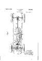
- Fig. 1 is a plan view of an automobile chassis equipped with my present invention.
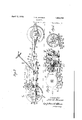
- Fig. 2 is a longitudinal vertical sectional view, taken along line 22 of Fig. 1.
- Fig. 3 is a longitudinal vertical sectional view, on a larger scale than in Fig. 2, showing the type of dynamoelectric means for driving the front wheels, also showing the novel engine cranking means.v
- Fig. 4 is a vertical cross-sectional. view, taken on line 4-4 of Fig. 3, showing the cranking means.
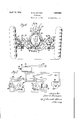
- Fig. 5 is an enlarged vertical sectional view, taken on line 5-5 of Fig. 1, showin a type of dynamo electric means referred or use n driving the two sets of w eels.
- Fig. 6 is an enlarged vertical cross-sec-' tional view, taken on line 6-6 of Fig. 2.
- Fig. 7 is a diagrammatic view of the dynamo electric machines and their electric connections, comprising the switches for selectively including both of the clutch generators for driving both pairs of wheels, or for including either one of said generators so as to drive either the front wheels or the rear wheels alone.
- t e automo ile be equipped with driving means for driving all 7, four wheels, so as to provide a safe and steady traction underthe various road conditions, and-to have such four wheel driving means operate as smoothly and noiselessly as possible.
- This driving means is referably so arranged that it may be use for driving only the front wheels, or onl the rear wheels, whenever such may be ound 55 advantageous or desirable for any reason.
- This prime mover is preferably an internal com- 99 bustion engine or gasoline engine E, and these dynamo electric machines preferably comprise a pair of clutch enerators G and G, one at the frontend an one at the rear end of .the engine, for driving the front wheels and the rear wheels, respectively; said dynamo electric machines further comprising a motor M which is electrically connected with both of said generators, and which receives electric current therefrom generated during the 109 starting speeds or first s these clutch generators.
- These generators said effort ortonue and the motor also have a battery B electrically connected therewith, as indicated in Fig.
- each clutch generator feeds current to said battery, for use for the lights, etc.
- These clutch generators are also utilized for starting'the engine, being energized by current from the battery.
- the two clutch generators G and G are connected to thetwo ends'of the engine shaft, the spider and field element of each being secured to and rotating with said shaft; an
- lgenerators are electrically connected in para el,-and are 0 erated through one controller, as indicated in Fig. 7.
- the motor is mounted at the rear of the generator G; while a change d and reverse gear mechanism C is moun on therear of the motor, as best shown in Fig. 5, and a similar gear mechanism C is mounted forward of the front nerator G.
- I preferably employ the type of dynamo electric machine used in the Owen magnetic car, wherein the driving mechanism has been arranged and provided only for driving the rear wheels, as disclosed by the Owen Patent No. 1.491,492, April 22, 1924.
- the use of such dynamo electric machines for driving the rear wheels therefore, is known and is not a part of my present invention.
- dynamo electric machines for driving the rear wheels, therefore, is known and is not a part of my present invention.
- sald rings bein connected electrically to the coils of the fiel s 24 and to the brushes 31.
- a ball-and-ring bearing or anti-friction bearing 34 is supported on the rear end of the engine shaft 21, and extends within the forward end of the hollow shaft 26, thus maintaining the forward end of said shaft 26 in perfect alinement with shaft 21.
- A- housing 36 is secured to and extends rearwardly from the casin 22 of the engine, serving as a cover for t e electrical elements and to support the field element 28 of the reir machine or motor M.
- a rear set of anti-friction bearings 37 are also sup iii:
- the hollow drive shaft 26 is geared at its rear end to a counter shaft39, through gearings 40 and 41.
- This counter shaft carries a reduction gear 42 and a gear 43 meshin with an idler 44.
- a shaft 45 is maintain in alinement with shaft 26, b suitable bearings 46 and 47, and is rovi ed with a slidable gear 48 having teet 49 which are adapt-' ed to engage similar teeth 50 carried at the rear end of shaft 26, for effecting a direct all four wheels of the automobile.
- namo electric means and mechanisms whereby to drive the front wheels in a' smooth and silent manner; so as to provide a complete, smooth and silent electric drive for I therefore employ another d amo electric machine, indicated in the d l 'iiwings as G, and mount it at the front end of the engine E.
- This machine is entirely similar in its parts to the above described dynamo electric machine G, and it has its spider23' secured to the front end of the engine shaft 21, as best shown in Fig. 3 ofthe drawings, in a similar manner as the spider 23 of machine G is secured to the rear end of said shaft.
- Said spider carries the field element 24' of this front machine G which also functions like a clutch generator like said machine G.
- the armature element 25' of this machine is carried by a hollow shaft 26' which extends forwardly of and is alined with engine shaft 21.
- a commutator 29' and brushes 31 to cooperate therewith are also provided; while collector rings .33 are mounted forwardly of spider 23', and anti-friction bearings 38' at the front end of the spider surround the hollow shaft 26, and bearings 37 support the front end of said shaft in the housing of change speed gear mechanism C.
- Said gear mechanism also includes the gears 40' and 4:1, and the associated gears and elements, like in ear mechanism O, as set forth above.
- Suita le levers are provided for operating the two sets of gear mechanisms in unison, the same preferably including an operating lever 51 suitably mounted and connected through a link 51 with a leverbar 52 which actuates a pair of rods 53 for operating a pair of arms 54 which extend into the gear mechanisms C and C, to operate the gears, in the well known manner.
- the fan 55 is mounted by a bracket 56 on the housing part of the front generator G in front of the engine. It is driven preferably by a belt 57 engaging a pulley 58 on the fan shaft and a pulley 59 on hollow shaft 26, forwardly of collector rings 33'.
- a control box 60 is suitably mounted on the automobile, and is operated by a controller 61, which is preferably mounted on the steering wheel and operates through a shaft 62,
- control box and connected control means are merely indicated diagram matically, as the same do not form a part of .this invention. 1 I
- a front axle is ositioned forwardly of the axial line throug the front wheels and is provided with a downwardly curved intermediate part 71, as best shown in- Figs. 1 and 6; so as to provide ample freedom of movement for the front differential mechanism Df with respect to the front axle.
- the front springs 72 are sup orted by said axle and have their front en s connected to the front ends of the frame bars 73 which have their rear ends supported through rear springs 74; on the rear axle housing.
- Said axle 70 has each of its end portions 75 curved rearwardly and provided with a yoke 76 wherein the steering knuckle 77 of one of the front Wheels is pivoted.
- Said front Wheels are steered through any suitable steering rod 78 and suitable connected steering mechanism.
- Strap means 79 are secured at the ends to said frame bars 73, and on the middle part thereof is su ported the front differential mechanism D, to have ample freedom of movement relative to the axle part 71, during flexing of the springs 72.
- the front driving axle means or transverse drive shaft means comprises a pair of shaft sections 80, which are connected at their inner ends through universal joints 81 with the two sides of the front differential gear mechanism, and are connected at their outer ends through universal joints'82 with the stub shafts of the front Wheelsffor driving the wheels, as is well understood.
- Novel and improved crank means is also provided herein for cranking the engine, in conjunction with this novel front wheel driving arrangement.
- This. means comprises a gear 85 which is preferably secured at the front of the spider 23, as best shown in Figs. 3 and 4, between-said spider and the collector rings 33'.
- a gear 86 is secured on the rear end of a rotatable operating shaft 87 which is supported in bearing knuckles 88 and 89 and has a clutch element 90 with clutch teeth on its front end, to be engaged and turned by cooperating clutch teeth on the end of a suit-- able crank lever 91.
- An idler 92 is pivotallv mounted on the upper arm 93 of a bellcrank 94 which is fulcrumed on shaft 87.
- An eccentric 95 on a shaft 96 engages in a forked end 97 of the bellcrank to swing the latter said shaft 96 being mounted in bracket means 98, so as to extend substantiall parallel to shaft 87, and said shaft 96 pre erably has a squared front end adapted to be fitted and actuated by said crank lever 91; so that by turning crank lever, 91 and sh ft 96 and its eccentric 95 the bellcrank 94 will be swung to positively move and hold the idler 92 in mesh with gear 85, while it is always in mesh with the other gear 86 secured on shaft 87.
- front and rear switch means for selectively cutting-out one ofsaid generators, thereby enabling the other generator to, drive the automobile through its associated pair of wheels.
- driving mechanism for driving the four wheels thereof c'omprising an engine and a pair of generators one at each end of said en 'ne, one alined drive shaft means including t e rotary shaft means of said engine and said generators, one generator for operatin the front wheels and the other generator or operating the rear wheels, through said drive shaft means, and means for selectively excluding either one of said generators and its wheels, while utilizin the other generator and its wheels for driving the automobile.
- a longitudinal drive shaft means having its shaft parts alined and having its two ends operatively connected to said differential mechanisms, means on said shaft means for driving the same and comprising a prime mover and a pair of clutch generators also a motor all inalinement on said shaft means, a enerator being. connected to each end of t e prime mover for driving one set of the wheels, the motor being equipped to receive the overload of current from the generators durin the starting speeds, and means for selective? exeluding either one of the generators and enable the other generator to drive the automobile through its set of wheels.
- collector ring means mounted forward of having one of its rotary electric elements secured t0 the front end of the engine shaft, a fan positioned on the housing of the generator and in front of the engine, and actuating means connected with said fan and with said generator for driving the fan to cool the engine.
Landscapes
- Engineering & Computer Science (AREA)
- Chemical & Material Sciences (AREA)
- Combustion & Propulsion (AREA)
- Transportation (AREA)
- Mechanical Engineering (AREA)
- Electric Propulsion And Braking For Vehicles (AREA)
- Arrangement And Driving Of Transmission Devices (AREA)
- Hybrid Electric Vehicles (AREA)
Description
April 12, 1932. B, s. JOHNSON AUTOMOB ILE 4 Sheets-Sheet 1 Filed Feb. 5, 1931 In 0672 Z10? fimrJaZ/ww April 12, 1932. a. G. JOHNSON AUTOMOBILE Filed Feb. 5, 1931 4 Sheets-Sheet 2 April 12, 1932- B. e. JOHNSON 1,853,058
AUTOMOBILE Filed Feb. 3, 1931 4 Sheets-Sheet 3 April 12, 1932. B. e. JOHNSON AUTOMOBILE Filed Feb. 3, 1931 4 Sheets-Sheet 4 Patented Apr. 12, 1932 UNITED STATES- PATENT OFFICE Application filed February 8, 1981 Serial No. 518,164.
This invention relates to improvements in an automobile; and more partlcularly to the type including front wheel and rear wheel driving mechanism.
- One of the main objects of this invention is to provide driving means for drivin all four wheels of an automobile, wherein t e entire driving means operates through one main line shaft means, thereby obviating the need 1c of any secondary shaft or sub-shaft in conjunction withthe main shaft and alongside thereof, and consequently avoiding the usual intermediate connecting gears as employed in the usual four-wheel driving mechanisms, which createhoise and annoyance.
Another object of this invention is to provide means and mechanism for driving all four wheels-of .an automobile in a silent and smooth manner, and whereby the speed can be readily increased and decreased evenly and rapidly, and either pair of wheels or both pairs may be utilized for driving the automobile, this being preferably accomplished r" by the use of several dynamo electric machines.
A further object is to provide improved driving means for driving the front wheels of a motor vehicle smoothly and noiselessly and A at a great variation of speeds, preferably 3 throughthe use of a dynamo electric machine operating in conjunction with the gasoline engine.
A still further object is to provide a novel M front axle construction for supporting the front part of the automobile equipped with this improved type of driving means.
Still another object is to provide a novel engine cranking means, wherein the cranking means can be moved and retained out of and into operative cranking position.
-Referring to the drawings:
' Fig. 1 is a plan view of an automobile chassis equipped with my present invention.
Fig. 2 is a longitudinal vertical sectional view, taken along line 22 of Fig. 1.
Fig. 3 is a longitudinal vertical sectional view, on a larger scale than in Fig. 2, showing the type of dynamoelectric means for driving the front wheels, also showing the novel engine cranking means.v
Fig. 4: is a vertical cross-sectional. view, taken on line 4-4 of Fig. 3, showing the cranking means.
Fig. 5 is an enlarged vertical sectional view, taken on line 5-5 of Fig. 1, showin a type of dynamo electric means referred or use n driving the two sets of w eels.
Fig. 6 is an enlarged vertical cross-sec-' tional view, taken on line 6-6 of Fig. 2.
Fig. 7 is a diagrammatic view of the dynamo electric machines and their electric connections, comprising the switches for selectively including both of the clutch generators for driving both pairs of wheels, or for including either one of said generators so as to drive either the front wheels or the rear wheels alone. i
In the present day rapidl travelin automobile it is desirable that t e automo ile be equipped with driving means for driving all 7, four wheels, so as to provide a safe and steady traction underthe various road conditions, and-to have such four wheel driving means operate as smoothly and noiselessly as possible.
I have therefore provided an improved drivmg means for driving all four wheels of an automobile of the present high-speed type, in a silent and smooth manner, andwhereb its acceleration and deceleration in'speed w' l be effected evenly and through an increased range of speeds. This driving means is referably so arranged that it may be use for driving only the front wheels, or onl the rear wheels, whenever such may be ound 55 advantageous or desirable for any reason.
For the purpose of this invention I em ploy a plurality of dynamo electric machines in conjunction with a prime. mover. This prime mover is preferably an internal com- 99 bustion engine or gasoline engine E, and these dynamo electric machines preferably comprise a pair of clutch enerators G and G, one at the frontend an one at the rear end of .the engine, for driving the front wheels and the rear wheels, respectively; said dynamo electric machines further comprising a motor M which is electrically connected with both of said generators, and which receives electric current therefrom generated during the 109 starting speeds or first s these clutch generators. These generators said effort ortonue and the motor also have a battery B electrically connected therewith, as indicated in Fig. 7; and when the field element and the armature element of each clutch generator travel substantially at the same speed, or become magnetically locked, this motor feeds current to said battery, for use for the lights, etc. These clutch generators are also utilized for starting'the engine, being energized by current from the battery.
The two clutch generators G and G are connected to thetwo ends'of the engine shaft, the spider and field element of each being secured to and rotating with said shaft; an
lgenerators are electrically connected in para el,-and are 0 erated through one controller, as indicated in Fig. 7. The motor is mounted at the rear of the generator G; while a change d and reverse gear mechanism C is moun on therear of the motor, as best shown in Fig. 5, and a similar gear mechanism C is mounted forward of the front nerator G. These two generators G and act as clutches in transmittingthe engine through the two gear mechanisms C an O and through the propelling means including the rear propeller shaft P,
to the rear and to the front differential mechanisms D and D, and therethrough to drive thveei'ear wheels and the front wheels, respecti Th e above related means and mechanisms, providing driving means for the front wheels and for the rear wheels of the automobile, are all mounted substantially in longitudinal alinement, and by the use of alined shaft means, as is best seen from Fig. 1 of the drawings, so that the entire driving means for all four wheels operates through one, straight, mainline shaft means. and provides a practically noiselessand eflicient drive means for both sets of wheels. I
In conjunction with the present invention I preferably employ the type of dynamo electric machine used in the Owen magnetic car, wherein the driving mechanism has been arranged and provided only for driving the rear wheels, as disclosed by the Owen Patent No. 1.491,492, April 22, 1924. The use of such dynamo electric machines for driving the rear wheels, therefore, is known and is not a part of my present invention. However,
' to prov de a silent four wheel driving mechanism, it became my problem and it became a part of this invention to rearrange and re-' .cOnstruct the forward parts of the automobile, including novel front axle and supporti means and front drive shaft means for driving the front wheels; and then to equip and suppl this novel front construction with the suitab e dynamo electric machine or mechend of said shaft is mounted a spider 23 to' which is secured the field element 24 of a dynamo electric machine, indicated as G herein. The armature element 25 of said machine is carried bythe shaft 26, which is hollow and is in alinement with the engine shaft 21. Said shaft 26 preferably carries an armature 27 of another dynamo electric mach ne, indicated herein as M ment 28 of which is stationary.
the field eleliach of these machines is shown provided with a com-- mutator 29, 30, wherewith the brushes'31, 32, respectively co-operate. The collector rings 33 are located between the two machines, be-
ing adapted to be engaged by the brushes,
sald rings bein connected electrically to the coils of the fiel s 24 and to the brushes 31.
A ball-and-ring bearing or anti-friction bearing 34 is supported on the rear end of the engine shaft 21, and extends within the forward end of the hollow shaft 26, thus maintaining the forward end of said shaft 26 in perfect alinement with shaft 21.
A- housing 36 is secured to and extends rearwardly from the casin 22 of the engine, serving as a cover for t e electrical elements and to support the field element 28 of the reir machine or motor M. A rear set of anti-friction bearings 37 are also sup iii:
ioe
the shaft 26 to rotate therein, thus also alining this field element 24 and its armature 25. The hollow drive shaft 26 is geared at its rear end to a counter shaft39, through gearings 40 and 41. This counter shaft carries a reduction gear 42 and a gear 43 meshin with an idler 44. A shaft 45 is maintain in alinement with shaft 26, b suitable bearings 46 and 47, and is rovi ed with a slidable gear 48 having teet 49 which are adapt-' ed to engage similar teeth 50 carried at the rear end of shaft 26, for effecting a direct all four wheels of the automobile.
namo electric means and mechanisms whereby to drive the front wheels in a' smooth and silent manner; so as to provide a complete, smooth and silent electric drive for I therefore employ another d amo electric machine, indicated in the d l 'iiwings as G, and mount it at the front end of the engine E. This machine is entirely similar in its parts to the above described dynamo electric machine G, and it has its spider23' secured to the front end of the engine shaft 21, as best shown in Fig. 3 ofthe drawings, in a similar manner as the spider 23 of machine G is secured to the rear end of said shaft. Said spider carries the field element 24' of this front machine G which also functions like a clutch generator like said machine G. The armature element 25' of this machine is carried by a hollow shaft 26' which extends forwardly of and is alined with engine shaft 21. A commutator 29' and brushes 31 to cooperate therewith are also provided; while collector rings .33 are mounted forwardly of spider 23', and anti-friction bearings 38' at the front end of the spider surround the hollow shaft 26, and bearings 37 support the front end of said shaft in the housing of change speed gear mechanism C. Said gear mechanism also includes the gears 40' and 4:1, and the associated gears and elements, like in ear mechanism O, as set forth above.
Suita le levers areprovided for operating the two sets of gear mechanisms in unison, the same preferably including an operating lever 51 suitably mounted and connected through a link 51 with a leverbar 52 which actuates a pair of rods 53 for operating a pair of arms 54 which extend into the gear mechanisms C and C, to operate the gears, in the well known manner.
In this invention the fan 55 is mounted by a bracket 56 on the housing part of the front generator G in front of the engine. It is driven preferably by a belt 57 engaging a pulley 58 on the fan shaft and a pulley 59 on hollow shaft 26, forwardly of collector rings 33'.
A control box 60 is suitably mounted on the automobile, and is operated by a controller 61, which is preferably mounted on the steering wheel and operates through a shaft 62,
' extending through the steering post, to actuate a shaft 63 extending forwardly of the control box. The control box and connected control means are merely indicated diagram matically, as the same do not form a part of .this invention. 1 I
"The electrical arrangements and connections of the two generators and the motor and the control means and battery are indi-.
floated diagrammatically by the wiring diagram shown in Fig. 7. This indicates how the electric connections between the two generators and the motor may be controlled through the controller; and shows the cut-out switches 64 and 64' provided in the parallel circuits 65 and 65 of the generators G and G, which lead through the controller to the motor and the battery. By opening either one of these switches 64 and 64 the particular generator and the associated driving means for its pair of wheels can be placed idle, whenever such action may be found expedient, as through a short occurring in the one generator, through breakage, etc.; and the other generator and the motor are then adapted to efficiently operate in driving the automobile through its associated pair of wheels.
A front axle is ositioned forwardly of the axial line throug the front wheels and is provided with a downwardly curved intermediate part 71, as best shown in- Figs. 1 and 6; so as to provide ample freedom of movement for the front differential mechanism Df with respect to the front axle. The front springs 72 are sup orted by said axle and have their front en s connected to the front ends of the frame bars 73 which have their rear ends supported through rear springs 74; on the rear axle housing. Said axle 70 has each of its end portions 75 curved rearwardly and provided with a yoke 76 wherein the steering knuckle 77 of one of the front Wheels is pivoted. Said front Wheels are steered through any suitable steering rod 78 and suitable connected steering mechanism. Strap means 79 are secured at the ends to said frame bars 73, and on the middle part thereof is su ported the front differential mechanism D, to have ample freedom of movement relative to the axle part 71, during flexing of the springs 72.
The front driving axle means or transverse drive shaft means comprises a pair of shaft sections 80, which are connected at their inner ends through universal joints 81 with the two sides of the front differential gear mechanism, and are connected at their outer ends through universal joints'82 with the stub shafts of the front Wheelsffor driving the wheels, as is well understood.
Novel and improved crank means is also provided herein for cranking the engine, in conjunction with this novel front wheel driving arrangement. This. means comprises a gear 85 which is preferably secured at the front of the spider 23, as best shown in Figs. 3 and 4, between-said spider and the collector rings 33'. A gear 86 is secured on the rear end of a rotatable operating shaft 87 which is supported in bearing knuckles 88 and 89 and has a clutch element 90 with clutch teeth on its front end, to be engaged and turned by cooperating clutch teeth on the end of a suit-- able crank lever 91. An idler 92 is pivotallv mounted on the upper arm 93 of a bellcrank 94 which is fulcrumed on shaft 87. An eccentric 95 on a shaft 96 engages in a forked end 97 of the bellcrank to swing the latter said shaft 96 being mounted in bracket means 98, so as to extend substantiall parallel to shaft 87, and said shaft 96 pre erably has a squared front end adapted to be fitted and actuated by said crank lever 91; so that by turning crank lever, 91 and sh ft 96 and its eccentric 95 the bellcrank 94 will be swung to positively move and hold the idler 92 in mesh with gear 85, while it is always in mesh with the other gear 86 secured on shaft 87. Thereupon the turning of shaft 87 with the crank lever will actuate the gears for cranking the engine, while these elements are in the position shown by the dotted lines in Fig. 4. After the cranking of the engine has been accomplished, the bellcrank 94 can be again swung back and the idler 92 thereby positively moved and held out of the operative osit-ion, as shown by the full lines in said Fig. 4.
It should be observed that a plurality of contacts and a plurality of starting speeds are provided for by the controller elements 60 to 63, as shown by Fi 7, and as is well understood in this art; Furthermore that a plurality of forward speeds are also provided for b the change speed gear mechanisms C and g and the associated lever and link elements 51 to 54, as employed in this construction. It thus becomes apparent that with this im roved construction and arran ement 0 elements and means and mec anisms, a comparatively wide range of speeds has been provided for, and that the acceleration and deceleration in speed can be effected through a comparatively wide range and in a very smooth and even manner; and that an improved, silent, electric four-wheel driving mechanism has been provided with this invention.
I claim as my invention:
1. In an automobile having front and rear wheels andfront and rear differential mechanisms to operate the same, a longitudinal and the other for driving the rear wheels.
2. In an automobile havin wheels and front and rear di erential mechanisms to operate the same, a lon itudinal drive shaft means-which has all its shaft parts substantially alined and has its two '-ends operatively connected to said two dif-.
ferential mechanisms, driving means on said shaft meansfor operating the same and including a pair of clutch generators, one thereof provided for driving the front wheels and the other for driving the rear wheels, and
front and rear switch means for selectively cutting-out one ofsaid generators, thereby enabling the other generator to, drive the automobile through its associated pair of wheels.
3. In an automobile, driving mechanism for driving the four wheels thereof, c'omprising an engine and a pair of generators one at each end of said en 'ne, one alined drive shaft means including t e rotary shaft means of said engine and said generators, one generator for operatin the front wheels and the other generator or operating the rear wheels, through said drive shaft means, and means for selectively excluding either one of said generators and its wheels, while utilizin the other generator and its wheels for driving the automobile.
4. In an automobile having front and rear wheels and front and rear differential mechanisms to operate the same, a longitudinal drive shaft means having its shaft parts alined and having its two ends operatively connected to said differential mechanisms, means on said shaft means for driving the same and comprising a prime mover and a pair of clutch generators also a motor all inalinement on said shaft means, a enerator being. connected to each end of t e prime mover for driving one set of the wheels, the motor being equipped to receive the overload of current from the generators durin the starting speeds, and means for selective? exeluding either one of the generators and enable the other generator to drive the automobile through its set of wheels.
5. In an automobile provided with front wheels and a differential mechanism and means extendin therefrom to the wheels to drive them, a riving engine, a generator having one of its rota electric elements secured to the front en of the engine shaft,
collector ring means mounted forward of having one of its rotary electric elements secured t0 the front end of the engine shaft, a fan positioned on the housing of the generator and in front of the engine, and actuating means connected with said fan and with said generator for driving the fan to cool the engine.
In testimony whereof I have signed this specification.
BROR G. JOHNSON.
Priority Applications (2)
| Application Number | Priority Date | Filing Date | Title |
|---|---|---|---|
| US513164A US1853058A (en) | 1931-02-03 | 1931-02-03 | Automobile |
| US542780A US1892348A (en) | 1931-02-03 | 1931-06-08 | Engine cranking mechanism |
Applications Claiming Priority (1)
| Application Number | Priority Date | Filing Date | Title |
|---|---|---|---|
| US513164A US1853058A (en) | 1931-02-03 | 1931-02-03 | Automobile |
Publications (1)
| Publication Number | Publication Date |
|---|---|
| US1853058A true US1853058A (en) | 1932-04-12 |
Family
ID=24042119
Family Applications (1)
| Application Number | Title | Priority Date | Filing Date |
|---|---|---|---|
| US513164A Expired - Lifetime US1853058A (en) | 1931-02-03 | 1931-02-03 | Automobile |
Country Status (1)
| Country | Link |
|---|---|
| US (1) | US1853058A (en) |
Cited By (11)
| Publication number | Priority date | Publication date | Assignee | Title |
|---|---|---|---|---|
| US2796943A (en) * | 1952-12-08 | 1957-06-25 | Ferguson Res Ltd Harry | Drive for independently suspended vehicle wheels |
| US3411601A (en) * | 1966-06-23 | 1968-11-19 | Gen Motors Corp | Plural drive axle vehicles with a separate torque apportioning drive train to each axle |
| US3416624A (en) * | 1966-10-20 | 1968-12-17 | Int Harvester Co | Tractor drive and load arrangement |
| US6461266B1 (en) | 2001-04-26 | 2002-10-08 | Ervin Weisz | Differential electric engine with variable torque conversion |
| WO2006034520A1 (en) * | 2004-09-27 | 2006-04-06 | Magna Steyr Fahrzeugtechnik Ag & Co Kg | Drive unit for motor vehicles with hybrid drive in a longitudinal arrangement |
| WO2008135838A3 (en) * | 2007-05-03 | 2009-05-07 | Ferrari Spa | Four-wheel drive hybrid vehicle |
| EP1657101A4 (en) * | 2003-08-18 | 2009-05-27 | Honda Motor Co Ltd | Hybrid vehicle |
| US20090321156A1 (en) * | 2008-06-25 | 2009-12-31 | Ford Global Technologies, Llc | Hybrid automotive powertrain system and method of operating same |
| WO2009019580A3 (en) * | 2007-08-07 | 2010-03-18 | Ferrari S.P.A. | Four -wheel -drive vehicle with hybrid propulsion |
| ITBO20090123A1 (en) * | 2009-03-03 | 2010-09-04 | Ferrari Spa | INTEGRAL TRACTION VEHICLE INSERTABLE |
| US20150224867A1 (en) * | 2012-08-27 | 2015-08-13 | Gkn Driveline International Gmbh | Vehicle electric and mechanical drive train |
-
1931
- 1931-02-03 US US513164A patent/US1853058A/en not_active Expired - Lifetime
Cited By (18)
| Publication number | Priority date | Publication date | Assignee | Title |
|---|---|---|---|---|
| US2796943A (en) * | 1952-12-08 | 1957-06-25 | Ferguson Res Ltd Harry | Drive for independently suspended vehicle wheels |
| US3411601A (en) * | 1966-06-23 | 1968-11-19 | Gen Motors Corp | Plural drive axle vehicles with a separate torque apportioning drive train to each axle |
| US3416624A (en) * | 1966-10-20 | 1968-12-17 | Int Harvester Co | Tractor drive and load arrangement |
| US6461266B1 (en) | 2001-04-26 | 2002-10-08 | Ervin Weisz | Differential electric engine with variable torque conversion |
| US6726588B2 (en) | 2001-04-26 | 2004-04-27 | Cvet Patent Technologies, Inc. | Differential electric engine with variable torque conversion |
| EP1657101A4 (en) * | 2003-08-18 | 2009-05-27 | Honda Motor Co Ltd | Hybrid vehicle |
| US20090200094A1 (en) * | 2004-09-27 | 2009-08-13 | Magna Steyr Fahrzeugtechnik Ag & Co Kg | Drive unit for motor vehicles with hybrid drive in a longitudinal arrangement |
| WO2006034520A1 (en) * | 2004-09-27 | 2006-04-06 | Magna Steyr Fahrzeugtechnik Ag & Co Kg | Drive unit for motor vehicles with hybrid drive in a longitudinal arrangement |
| US7661495B2 (en) | 2004-09-27 | 2010-02-16 | Magna Steyr Fahrzeugtechnik Ag & Co. Kg | Drive unit for motor vehicles with hybrid drive in a longitudinal arrangement |
| WO2008135838A3 (en) * | 2007-05-03 | 2009-05-07 | Ferrari Spa | Four-wheel drive hybrid vehicle |
| WO2009019580A3 (en) * | 2007-08-07 | 2010-03-18 | Ferrari S.P.A. | Four -wheel -drive vehicle with hybrid propulsion |
| US20090321156A1 (en) * | 2008-06-25 | 2009-12-31 | Ford Global Technologies, Llc | Hybrid automotive powertrain system and method of operating same |
| ITBO20090123A1 (en) * | 2009-03-03 | 2010-09-04 | Ferrari Spa | INTEGRAL TRACTION VEHICLE INSERTABLE |
| US20100224431A1 (en) * | 2009-03-03 | 2010-09-09 | Franco Cimatti | Optionally connectable four-wheel drive vehicle |
| EP2228249A1 (en) | 2009-03-03 | 2010-09-15 | FERRARI S.p.A. | Optionally connectable four-wheel drive vehicle |
| US8047322B2 (en) * | 2009-03-03 | 2011-11-01 | Ferrari S.P.A. | Optionally connectable four-wheel drive vehicle |
| US20150224867A1 (en) * | 2012-08-27 | 2015-08-13 | Gkn Driveline International Gmbh | Vehicle electric and mechanical drive train |
| US9694662B2 (en) * | 2012-08-27 | 2017-07-04 | Gkn Automotive Ltd. | Vehicle electric and mechanical drive train |
Similar Documents
| Publication | Publication Date | Title |
|---|---|---|
| US1853058A (en) | Automobile | |
| US2047050A (en) | Driving and steering axle unit | |
| US4464945A (en) | Gear mechanism for motor vehicles | |
| US2113102A (en) | Electrical torque transmission | |
| US1179407A (en) | Electric truck. | |
| JP2020002959A (en) | Vehicle drive | |
| US859368A (en) | Dynamo-electric machine. | |
| US871098A (en) | Means for driving motor road-vehicles. | |
| WO2001000988A1 (en) | Independent electric power systems of electrical cars | |
| US1515322A (en) | Controlling system for electromagnetic transmission mechanism | |
| US1706276A (en) | Electric transmission system | |
| US1819626A (en) | Power transmission device | |
| US1341223A (en) | Transmission of power | |
| US1849755A (en) | Driving mechanism for motor vehicles | |
| US1321898A (en) | Driving-wheel for autojhophes and other vehicles | |
| US1093149A (en) | Driving mechanism for electrically-propelled vehicles. | |
| US1556707A (en) | Motor vehicle | |
| US1064089A (en) | Motor-vehicle. | |
| US1679805A (en) | Three-axled motor vehicle | |
| US1442908A (en) | Transmission mechanism | |
| US1253670A (en) | Motor-vehicle. | |
| US1276045A (en) | Transmission and control for motor-vehicles. | |
| US843788A (en) | Electric locomotive. | |
| GB624179A (en) | Improvements in or relating to electro-mechanical power transmission systems | |
| US1428693A (en) | Axle-driven-transmission mechanism |