US1853048A - Cutting and piercing apparatus - Google Patents
Cutting and piercing apparatus Download PDFInfo
- Publication number
- US1853048A US1853048A US399534A US39953429A US1853048A US 1853048 A US1853048 A US 1853048A US 399534 A US399534 A US 399534A US 39953429 A US39953429 A US 39953429A US 1853048 A US1853048 A US 1853048A
- Authority
- US
- United States
- Prior art keywords
- cutting
- cutter
- punch
- ratchet
- saw
- Prior art date
- Legal status (The legal status is an assumption and is not a legal conclusion. Google has not performed a legal analysis and makes no representation as to the accuracy of the status listed.)
- Expired - Lifetime
Links
Images
Classifications
-
- B—PERFORMING OPERATIONS; TRANSPORTING
- B23—MACHINE TOOLS; METAL-WORKING NOT OTHERWISE PROVIDED FOR
- B23P—METAL-WORKING NOT OTHERWISE PROVIDED FOR; COMBINED OPERATIONS; UNIVERSAL MACHINE TOOLS
- B23P23/00—Machines or arrangements of machines for performing specified combinations of different metal-working operations not covered by a single other subclass
- B23P23/04—Machines or arrangements of machines for performing specified combinations of different metal-working operations not covered by a single other subclass for both machining and other metal-working operations
-
- Y—GENERAL TAGGING OF NEW TECHNOLOGICAL DEVELOPMENTS; GENERAL TAGGING OF CROSS-SECTIONAL TECHNOLOGIES SPANNING OVER SEVERAL SECTIONS OF THE IPC; TECHNICAL SUBJECTS COVERED BY FORMER USPC CROSS-REFERENCE ART COLLECTIONS [XRACs] AND DIGESTS
- Y10—TECHNICAL SUBJECTS COVERED BY FORMER USPC
- Y10T—TECHNICAL SUBJECTS COVERED BY FORMER US CLASSIFICATION
- Y10T29/00—Metal working
- Y10T29/51—Plural diverse manufacturing apparatus including means for metal shaping or assembling
Definitions
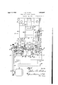
- Fig. 1 is a front elevation partly in sec tion taken on line 1-1 of Fig.2 showlng a preferred form of the resent nvention.
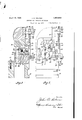
- Fig. 2 is aside elevation lookmgin the d1- i'ection of the arrow 2 of Fig. 1.
- Fig. 3 is a sectional view on the line 3-3- of Fig. 1.
- Fig. 4 is a sectional view on the line 44 of F1g. 1.
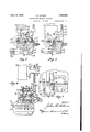
- Fi' 5 is a sectional view on thelme 5-5 of "Fig. 1, showing the pierclng punch and the cutting saw in retracted position.
- Fig. 6 is a sectional view similar to Fig. 5 showing the saw and punch in operating position.
- Fig. 7 is a fragmentary plan v1e w partly in section, the sectional view being taken on the line 77 of Fig.11.
- the punch press- which supports and opcrates the various mechanism which form the connecting rod 28- liingedly connected withthe head 26, and cooperating with an eccentric 4 29 operated by the main shaft 30 of the punch ress.
- the ar of stock A which may be L- shaped in cross-section or any other shape, is fed toward the tools for cutting and piercing by an automatic feeding mechanism which, as shown in Figs. 1 and 4, comprises feed rolls 31 and 32 driven by shafts 33 and 34 respectively which are connected respectively with meshed ears 35 and 36.
- the shaft .33 is supports by bearings 37 carried by the frame 22.
- the shaft 34 is journalled-in bearings 38, which are guided for vertical sliding movement by surfaces which define -the notches 39 provided by a block 40 resting upon and attached to the frame 22.
- Springs 41 urge the bearings 38 downwardly and cause the roller 32' to press the bar.v A against the roller 31.
- the shaft 33 is connected with a friction clutch-disc 42 and supports a ratchet wheel 43 loosely journalled on the shaft 33.
- Aefriction disc 44 which is drivingly connected with the disc 42, is located between the disc 42 and the ratchet 43.
- the washer 46 is urged against the hub of the ratchet 43.
- the Washer 47 is urged against nuts 48 threaded on the extension 49 of the shaft 33.
- the hub of the ratchet 43 supports a lever 51a which pivotally supports pawls 51 urged by springs 52 against the ratchet 43.
- the lever 51a is connected by a screw 53 with a rod 54.
- the rod 54 is provided with a slot 55 for receiving the bar 56 attached by screws 57 to the block 25.
- the bar 54 includes a cylindrical portion 58 which extendsthrough a hole 59 in a bracket 60 attached by screws 61' to the way 27.
- a spring 62 is located between the shoulder 63 of the bar 54 and awasher 64 bearing against the bracket 60..
- the part 58 is threaded at 65 for receiving nuts 66 and 67.
- the spring 62 When the head 26 moves downwardly the spring 62 will be permitted to expand in order to move [the rod'54 downwardly until the flange 66a of the nut 66 rests upon the bracket 60. Further downward movement of the rod 54 will not take lace since the notch 55 provides clearance or the bar 56. Thus, the notch 55 cooperates with the bar 56 to provide a lost motion connect1on between the head 26 and the rod 54. Thls 1s desirable since the amount of motion required for operating the tools is greater than that necessary for feeding the strip A toward the tools. During the downward movement of the rod 54 the lever 51a moves clockwise in order to back the pawls 51 away from the teeth of the ratchet 43.
- the ratchet 43 is prevented from rotating clockwise by a pawl 68 pivoted upon a screw 69 attached to the block 40 and urged against the pawl by the spring 70 attached by screw 71 to the block 40.
- the angular distance through which the pawls are backed up can be varied by adjusting the nut 66 along the rod 54. ThlS same adjustment varies the angular distance through which the ratchet 43 is rotated when the head 26 moves upwardly.
- the bar 56 will at first move free of the rod 54, but finally will engage the rod 54 at the upper end of notch 55 in order to cause the awls 51 to rotate the ratchet 43 countercloc wise as viewed in Fig. 1.
- This motion is accompanied by s1m1- lar motion of feed wheel 31 and consequent clockwise rotation of the feed wheel 32 in order to cause the strip A to be fed toward the left in Fig. 1.
- the strip A is fed through a suitable channel provided by hard metal wear pleces 72 and 73 which, as shown in Fig. 3, are carried respectively by the frame 22 and the block 40.
- the strip A is fed toward the left until its left hand end as viewed in Fig. 7 engages a stop 75 provided by a block 76 which is attached by a screw 77 to the frame 22 and is held in position by dowel 78.
- the block 76 provides a hole 79 for piloting a punch 80 attached to the block 25 by a screw 81.
- the punch 80 cooperates with a die member 82 secured by a nut 83 within a suitable recess 84 provided by a frame 22 as shown in Figs. 5 and 6.
- the block 76 provides both the stop surface 75 and the pilot hole 79 for the punch 80, and hence provides for accurate location of the hole B, pierced by the punch 80 in the bar A as shown in Fig. 7, with relation to one of the side surfaces of the piece which is to be cut off from the bar A.
- the strip severing saw is located in a plane as close as possible to the punch 80.
- the die 82 is rovided with a notch 91.
- aw 90 is mounted upon and driven b a shaft 92 journalled in bearings 93 provi ed b a saw shaft frame 94, which is slidable albng ways 95 and 96 secured to the frame 22, and is slidable in a direction parallel to a plane of the saw.
- the shaft 92 is rotated by an electric motor 97 which drives a pulley 98 connected by a belt 99 with a pulley 100 connected with the shaft 92.
- the saw shaft frame 94 is normally maintained in the position shown also in Fi 5 by a spring 101 having one end receive b a spring socket 102 in the saw frame 94 and avingits other end received by a socket 193 in a bracket 104 attached by screws 105 to the frame 22.
- the saw 90 is moved from the position shown in Fig. 5 to that shown in Fig. 6 by a cam bar attached b screws 111 to the block 25 which is actuated by the head 26.
- the cam 110 cooperates with a follower 112 secured by screws 113 and 114 to the saw frame 94.
- the next succeeding downward movement of the head 26 will cause the punch 80 to cooperate with the die 82 to punch the hole B in the strip A, and the rotating saw 90 will move from the position shown in Fi 5 to that shown in Fig. 6 in order to cut 0 from the strip A that small portion A adjacent its end which has been punched.
- this iece A After this iece A has been cut off it will be ejected rom its previous location between the die 80 and the block 7 6 by a jet of compressed. air issuing from a nozzle orifice connected by a tube 121 with a source of compressed air. The piece will be blown at least as far as the position A shown in Fig. 5.
- the saw 90 and the punch 80 are retracted from the strip A and the strip A is fed toward the left against the stop surface 7 5.
- the travel of the ratchet 43 is made greater than necessary.
- the ratchet 43 may continue to move counterclockwise as viewed in Fig. 1. This over-travel of the ratchet 43 is permitted by reason of the friction clutch connection between the ratchet 43 and shaft 33.
- Apparatus for cutting and piercing a length of material comprising, in combination, a base adapted to be supported by the table of a punch press, and providing a support along which the material is movable, a
- rotary cutter carried by the base and guided for bodily movements laterally of its axis, a hole piercing device movable at right angles to the plane of the material, means for moving the cutter toward the work and including a bar cam movable in a direction parallel to the movement of the piercing device, and a block for carrying the bar cam and piercin device and adapted to be attached to the hea of a punch press.
- Apparatus according to claim 1 further characterized as having material feeding means comprisin feed rolls and feed roll operating mechanism adapted to be actuated by the head of a punch press.
- Apparatus or cutting a length of material comprising a rotary cutter, means for moving the cutter edgewise into the material, a stop located at a certain position relative to the plane of the cutter, and means for feeding the work against the stop while the cutter is retracted and comprising feed rolls, means for intermittently rotating the feed rolls and a friction clutch for transmitting motion from said means to the rolls, said means being operated to an extent eater than necessary for feeding'the material, the clutch slipping after the material has engaged the stop.
- Apparatus for cutting a length of material comprising a rotary cutter, means for moving the cutter edgewise into the material, a stop located at a certain position 7 relative to the plane of the cutter, means for feeding the work against the sto while the cutter is retracted, and means or ejecting the piece cut off.
- Apparatus for cutting a length of material comprising arotary cutter, means for moving the cutter edgewise into the material, a stop located at a certain position relative to the plane of the cutter, means for feeding the work against the stop while the cutter is retracted, and means including an air nozzle located between the' cutter and stop to direct a jet of air against the piece cut off in order to remove it.
Description
April 12, 1932.
J. Q. HOLMES CUTTING AND PIERCING APPARATUS Filed Oct. 14, 1929 3 Sheet-Sheet l A rii 12, 1932.
IHHIIIIHIHH J. Q. HOLMES 1,853,048
CUTTING AND PIERCING APPARATUS Filed Oct. 14, 1929 5 Sheets-Sheet 2 CUTTING AND PIERCING APPARATUS 3 Sheets-Sheet 5 Filed Oct. 14, 1929 Patontod Apr. 12, 1932 UNITED ST TES JOHN G. HOE-IE8, OI ANDERSON, INDIANA,
PATENT OFFICE" ASBIGNOB TO DELCO-BEMY GOBPOBATIQH,
or ANDERSON, mmura'a conrom'rrox or nmwa'nr.
corms arm rmacme arrmrus Application fled October 14, 1829. Serial No. 399,584.
durable construction for economical y roducin ieces of the kind described. his aim o the present inventlon is accomplished by mechamsm which ma beattached to a unch press and operate by its rec1procatin cross head.
urther objects and advantages of the present invention will be apparent from the followingv description, reference be1ng had to the accom anying, drawings wherein a preferred em odiment-of one form of the present invention is clearly shown.
In the drawings: 7
Fig. 1 is a front elevation partly in sec tion taken on line 1-1 of Fig.2 showlng a preferred form of the resent nvention. .Fig. 2 is aside elevation lookmgin the d1- i'ection of the arrow 2 of Fig. 1.
Fig. 3 is a sectional view on the line 3-3- of Fig. 1.
Fig. 4 is a sectional view on the line 44 of F1g. 1.
Fi' 5 is a sectional view on thelme 5-5 of "Fig. 1, showing the pierclng punch and the cutting saw in retracted position. g
35 Fig. 6 is a sectional view similar to Fig. 5 showing the saw and punch in operating position.
Fig. 7 is a fragmentary plan v1e w partly in section, the sectional view being taken on the line 77 of Fig.11.
The punch press-which supports and opcrates the various mechanism which form the connecting rod 28- liingedly connected withthe head 26, and cooperating with an eccentric 4 29 operated by the main shaft 30 of the punch ress.
The ar of stock A, which may be L- shaped in cross-section or any other shape, is fed toward the tools for cutting and piercing by an automatic feeding mechanism which, as shown in Figs. 1 and 4, comprises feed rolls 31 and 32 driven by shafts 33 and 34 respectively which are connected respectively with meshed ears 35 and 36. The shaft .33 is supports by bearings 37 carried by the frame 22. The shaft 34 is journalled-in bearings 38, which are guided for vertical sliding movement by surfaces which define -the notches 39 provided by a block 40 resting upon and attached to the frame 22. Springs 41 urge the bearings 38 downwardly and cause the roller 32' to press the bar.v A against the roller 31. The shaft 33 is connected with a friction clutch-disc 42 and supports a ratchet wheel 43 loosely journalled on the shaft 33. Aefriction disc 44, which is drivingly connected with the disc 42, is located between the disc 42 and the ratchet 43.
These friction members are held into engagement by spring 45 located between washers 46 and 47 surrounding the shaft 33. The washer 46 is urged against the hub of the ratchet 43. The Washer 47 is urged against nuts 48 threaded on the extension 49 of the shaft 33. The hub of the ratchet 43 supports a lever 51a which pivotally supports pawls 51 urged by springs 52 against the ratchet 43. The lever 51a is connected by a screw 53 with a rod 54. The rod 54 is provided with a slot 55 for receiving the bar 56 attached by screws 57 to the block 25. The bar 54 includes a cylindrical portion 58 which extendsthrough a hole 59 in a bracket 60 attached by screws 61' to the way 27. A spring 62 is located between the shoulder 63 of the bar 54 and awasher 64 bearing against the bracket 60.. The part 58 is threaded at 65 for receiving nuts 66 and 67.
When the head 26 moves downwardly the spring 62 will be permitted to expand in order to move [the rod'54 downwardly until the flange 66a of the nut 66 rests upon the bracket 60. Further downward movement of the rod 54 will not take lace since the notch 55 provides clearance or the bar 56. Thus, the notch 55 cooperates with the bar 56 to provide a lost motion connect1on between the head 26 and the rod 54. Thls 1s desirable since the amount of motion required for operating the tools is greater than that necessary for feeding the strip A toward the tools. During the downward movement of the rod 54 the lever 51a moves clockwise in order to back the pawls 51 away from the teeth of the ratchet 43. The ratchet 43 is prevented from rotating clockwise by a pawl 68 pivoted upon a screw 69 attached to the block 40 and urged against the pawl by the spring 70 attached by screw 71 to the block 40. The angular distance through which the pawls are backed up can be varied by adjusting the nut 66 along the rod 54. ThlS same adjustment varies the angular distance through which the ratchet 43 is rotated when the head 26 moves upwardly. When the head 26 moves upwardly the bar 56 will at first move free of the rod 54, but finally will engage the rod 54 at the upper end of notch 55 in order to cause the awls 51 to rotate the ratchet 43 countercloc wise as viewed in Fig. 1. This motion is accompanied by s1m1- lar motion of feed wheel 31 and consequent clockwise rotation of the feed wheel 32 in order to cause the strip A to be fed toward the left in Fig. 1.
The strip A is fed through a suitable channel provided by hard metal wear pleces 72 and 73 which, as shown in Fig. 3, are carried respectively by the frame 22 and the block 40. The strip A is fed toward the left until its left hand end as viewed in Fig. 7 engages a stop 75 provided by a block 76 which is attached by a screw 77 to the frame 22 and is held in position by dowel 78.
The block 76 provides a hole 79 for piloting a punch 80 attached to the block 25 by a screw 81. The punch 80 cooperates with a die member 82 secured by a nut 83 within a suitable recess 84 provided by a frame 22 as shown in Figs. 5 and 6. The block 76 provides both the stop surface 75 and the pilot hole 79 for the punch 80, and hence provides for accurate location of the hole B, pierced by the punch 80 in the bar A as shown in Fig. 7, with relation to one of the side surfaces of the piece which is to be cut off from the bar A. In order to provide accurate location of the hole B with respect to the other side edge of the piece to be cut off, the strip severing saw is located in a plane as close as possible to the punch 80. To provide clearance for the saw 90 the die 82 is rovided with a notch 91.
aw 90 is mounted upon and driven b a shaft 92 journalled in bearings 93 provi ed b a saw shaft frame 94, which is slidable albng ways 95 and 96 secured to the frame 22, and is slidable in a direction parallel to a plane of the saw. The shaft 92 is rotated by an electric motor 97 which drives a pulley 98 connected by a belt 99 with a pulley 100 connected with the shaft 92. Referring to Figs. 2 and 7 the saw shaft frame 94 is normally maintained in the position shown also in Fi 5 by a spring 101 having one end receive b a spring socket 102 in the saw frame 94 and avingits other end received by a socket 193 in a bracket 104 attached by screws 105 to the frame 22.' The saw 90 is moved from the position shown in Fig. 5 to that shown in Fig. 6 by a cam bar attached b screws 111 to the block 25 which is actuated by the head 26. The cam 110 cooperates with a follower 112 secured by screws 113 and 114 to the saw frame 94.
The strip A, having been fed against the stop surface 75 of the block 76 during a preceding upward movement of the head 26,
the next succeeding downward movement of the head 26 will cause the punch 80 to cooperate with the die 82 to punch the hole B in the strip A, and the rotating saw 90 will move from the position shown in Fi 5 to that shown in Fig. 6 in order to cut 0 from the strip A that small portion A adjacent its end which has been punched. After this iece A has been cut off it will be ejected rom its previous location between the die 80 and the block 7 6 by a jet of compressed. air issuing from a nozzle orifice connected by a tube 121 with a source of compressed air. The piece will be blown at least as far as the position A shown in Fig. 5. From this position it may fall into a suitable receptacle located below the holes 122 and 123 provided by the frame 22 and the base 20 respectively. The slugs punched out descend through openings'centrally located in the die 82 and nut 83 and through a hole 124 in the base 20.
During the upward movement of the punch press head 26 the saw 90 and the punch 80 are retracted from the strip A and the strip A is fed toward the left against the stop surface 7 5. In order to assure that the strip A will have been moved against the surface 75 the travel of the ratchet 43 is made greater than necessary. After the strip A has engaged the surface 75 the ratchet 43 may continue to move counterclockwise as viewed in Fig. 1. This over-travel of the ratchet 43 is permitted by reason of the friction clutch connection between the ratchet 43 and shaft 33.
While the form of embodiment of the present invention as herein disclosed, constitutes a preferred form, it is to be understood that other forms might be adopted, all coming within the scope of the claims which follow.
What is claimed is as follows:
1. Apparatus for cutting and piercing a length of material comprising, in combination, a base adapted to be supported by the table of a punch press, and providing a support along which the material is movable, a
rotary cutter carried by the base and guided for bodily movements laterally of its axis, a hole piercing device movable at right angles to the plane of the material, means for moving the cutter toward the work and including a bar cam movable in a direction parallel to the movement of the piercing device, and a block for carrying the bar cam and piercin device and adapted to be attached to the hea of a punch press.
2. Apparatus according to claim 1 further characterized as having material feeding means comprisin feed rolls and feed roll operating mechanism adapted to be actuated by the head of a punch press.
3. Apparatus or cutting a length of material and comprising a rotary cutter, means for moving the cutter edgewise into the material, a stop located at a certain position relative to the plane of the cutter, and means for feeding the work against the stop while the cutter is retracted and comprising feed rolls, means for intermittently rotating the feed rolls and a friction clutch for transmitting motion from said means to the rolls, said means being operated to an extent eater than necessary for feeding'the material, the clutch slipping after the material has engaged the stop.
4. Apparatus for cutting a length of material and comprising a rotary cutter, means for moving the cutter edgewise into the material, a stop located at a certain position 7 relative to the plane of the cutter, means for feeding the work against the sto while the cutter is retracted, and means or ejecting the piece cut off.
5. Apparatus for cutting a length of material and comprisingarotary cutter, means for moving the cutter edgewise into the material, a stop located at a certain position relative to the plane of the cutter, means for feeding the work against the stop while the cutter is retracted, and means including an air nozzle located between the' cutter and stop to direct a jet of air against the piece cut off in order to remove it.
In testimony whereof I hereto afiix my sig- JOHN o. HOLMES.
' nature.
Priority Applications (1)
| Application Number | Priority Date | Filing Date | Title |
|---|---|---|---|
| US399534A US1853048A (en) | 1929-10-14 | 1929-10-14 | Cutting and piercing apparatus |
Applications Claiming Priority (1)
| Application Number | Priority Date | Filing Date | Title |
|---|---|---|---|
| US399534A US1853048A (en) | 1929-10-14 | 1929-10-14 | Cutting and piercing apparatus |
Publications (1)
| Publication Number | Publication Date |
|---|---|
| US1853048A true US1853048A (en) | 1932-04-12 |
Family
ID=23579890
Family Applications (1)
| Application Number | Title | Priority Date | Filing Date |
|---|---|---|---|
| US399534A Expired - Lifetime US1853048A (en) | 1929-10-14 | 1929-10-14 | Cutting and piercing apparatus |
Country Status (1)
| Country | Link |
|---|---|
| US (1) | US1853048A (en) |
Cited By (1)
| Publication number | Priority date | Publication date | Assignee | Title |
|---|---|---|---|---|
| US8960284B2 (en) | 2012-08-29 | 2015-02-24 | Halliburton Energy Services, Inc. | Methods of hindering the settling of proppant aggregates |
-
1929
- 1929-10-14 US US399534A patent/US1853048A/en not_active Expired - Lifetime
Cited By (1)
| Publication number | Priority date | Publication date | Assignee | Title |
|---|---|---|---|---|
| US8960284B2 (en) | 2012-08-29 | 2015-02-24 | Halliburton Energy Services, Inc. | Methods of hindering the settling of proppant aggregates |
Similar Documents
| Publication | Publication Date | Title |
|---|---|---|
| US2301236A (en) | Apparatus for operating on sheet material | |
| US3446499A (en) | Sheet material handling apparatus | |
| US1853048A (en) | Cutting and piercing apparatus | |
| US2672835A (en) | Sheet feeding mechanism | |
| US1859372A (en) | Feeding apparatus | |
| US2156323A (en) | Cut-off machine | |
| US2019518A (en) | Strip stock feeding and gauging | |
| US3555864A (en) | Slat accessory machine | |
| US3077966A (en) | Press control device | |
| US2598106A (en) | Drilling attachment for riveting machines | |
| US2096346A (en) | Bottle cap-making and applying machine | |
| US2614515A (en) | Hood forming machine | |
| US1132626A (en) | Paper-cutting machine. | |
| US2339756A (en) | Sheet feeding method and gauging mechanism therefor | |
| US2664159A (en) | Selectively operable cutoff mechanism for marking machines | |
| US3554533A (en) | Sheet material-handling apparatus | |
| US1883996A (en) | Scrap cutter for punch presses and the like | |
| US2101083A (en) | Press gauge | |
| US2155396A (en) | Flying shear | |
| US859220A (en) | Device for feeding and cutting strips. | |
| US1482025A (en) | Cutting and punching machine | |
| US2289841A (en) | Metal press | |
| US1054778A (en) | Machine for cutting labels. | |
| US3112660A (en) | Machine for forming metal articles | |
| US2047337A (en) | Edging of fabrics or other materials |