US1853039A - Uni-control tuning apparatus - Google Patents
Uni-control tuning apparatus Download PDFInfo
- Publication number
- US1853039A US1853039A US61409A US6140925A US1853039A US 1853039 A US1853039 A US 1853039A US 61409 A US61409 A US 61409A US 6140925 A US6140925 A US 6140925A US 1853039 A US1853039 A US 1853039A
- Authority
- US
- United States
- Prior art keywords
- tuning
- gear
- control
- gears
- elements
- Prior art date
- Legal status (The legal status is an assumption and is not a legal conclusion. Google has not performed a legal analysis and makes no representation as to the accuracy of the status listed.)
- Expired - Lifetime
Links
Images
Classifications
-
- H—ELECTRICITY
- H03—ELECTRONIC CIRCUITRY
- H03J—TUNING RESONANT CIRCUITS; SELECTING RESONANT CIRCUITS
- H03J1/00—Details of adjusting, driving, indicating, or mechanical control arrangements for resonant circuits in general
- H03J1/06—Driving or adjusting arrangements; combined with other driving or adjusting arrangements, e.g. of gain control
- H03J1/08—Toothed-gear drive; Worm drive
Definitions
- the, dials are marked with indications for locating the same position of thetuning element at which a station has been heard before.
- the'set is so designed that a numerical or other type of marking will be I the same for each dial so that within definite "ranges of wave lengths, the same. rotation of all dials produces the same timing for that wavelength.
- This arrangement relates articularly to the use of several gears, chain drives or the equivalent connected to the respective operating shafts and dials forthe various control elements.
- a Vernier is geared or otherwise connected to one dial.
- Another gear meshes with the gear on this first dial and cooperates with that on another dial.
- This intermediate gear is .so designed and arranged that an appreciable amount of lost motion will ex ist between the two dials. If a third dial is used, another intermediate lost motion gear may connect that with the second mentioned 0 dial so that the greatest amount of lost mo tion will exist between the first dial and the third.
- Dials 2eand 3 will log together, but dial #1 has always a slightly different setting.
- This invention uses a cam system or other slow motion arrangement for decreasing the amount ofregeneration with increase of frequency of signal and vice versa:
- This cam arrangement for controlling these regeneration may be attached to any one of the'difi'erent gears. This provides an easy and simple method of operating the tuning elements and the amount oflost motion may beused to double eflic'iencyby approaching the critical tuning point, on the dial at the end I of the gear train from-either direction.
- the lost motion or back-lash as. it is often called, can be used to control the other gears in the opposite direction by approaching the critical point of the third or last dial in the reverse direction and a difler- I cut adjustment may be obtained throughout therange of the backlash.
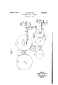
- Fig. 1 is a view of the gearing arrangement whereby two tuning elements and a regeneration control are operated and Fig. 2 is a modification of the form shown in Fig. 1 with an additional control element.
- a is a vernier or reduction speed gear connection having the manual control knob not shown.
- This vernier gear is connected directly to one of the control elements attached to shaft 0 by meshing with ear 0.
- This control element may be a condenser, movable coil or other equivalent apparatus.
- the fit between the teeth of gears a and 0 should be reasonably accurate and no loose play is necessary here.
- 9 is a small intermediate gear which also meshes with 0 cooperating with the gear 6 mounted on the control shaft d of another control element such as condenser movable coil or the like. If a third control element is used, another gear Q and Z) will be required.
- the cam 7" On the shaft 6 is mounted the cam 7" which is engaged by the lever g pivoted at h.
- the lever 9 extends beyond it and ends in the terminal k.
- 0 is a shaft operating the regenoration control such as tickler, condenser, rheostat or the like, as shown at p.
- Rigidly connected to this shaft is the arm 7, biased in one direction by spring m, fastened to rigid support 12.
- the terminal holds the arm Z against the bias of the spring
- This operation may leave the dial connected to gear 0 at a oint slightly off the most efficient tuning. pon rotating the vernier gear a in the reverse direction, this inaccuracy may be corrected within the limits of the lost motion roduced in intermediate gear
- the regu ation of the regeneration control p is automatically taken care of during this operation by the cam f, which increases through regeneration at lower signal frequencies and decreases at higher.
- a third control shaft 6 has been geared directly to the control shaft 6, so that the control elements 6 and e are tuned as a single unit, there being, no lost motion between 6 and 6, while the control element (l is as in Fig. 1 operated through the lost motion gear g whereby the control element (Z may be adjusted separately.
- the cam f is shown on the control element 6, although it could be 10- cated in any one of the control elements.
- the vernier a is shown driving the gear 0' although the vernier a could be meshed with either 0 or 0.
- the regenerative control shown in this modification is similar to the one shown in Fig. 1.
- tuning dials In combination, tuning dials, tuning elements attached thereto, a gear attached to each tuning element, regeneration control dial, regeneration control elements attached.
- means for interconnecting said elements including lost motion gears between the tuning element gears, a single operator acting directly on one of said tuning dials and indirectly through said inter-connecting means on others of said tuning dials, whereby the lost motion in said, inter-connecting means may be used to obtain a final adjustment between said dials and means associated with one of said tuning elements to operate said regenerative control.
- tuning indicators tuning elements attached thereto, gears for inter-connecting said indicators having a lost motion adjustment, and a single operating gear acting directly on one of said first named gears and indirectly through said inter-connecting gears on another of said first named gears.
- tuning elements associated with each circuit, gearing means connected to, the tuning elements and arranged for interconnecting said tuning elements for simultaneous adjustment, said gearing means having lost motion 7 connections between portions thereof connected to the tuning elements of said circuits whereby simultaneous 'adjust ment of all of said tuning elements and small individual adjustments of each of two elements maybe secured.
- tuning elements associated wit each of said circuits, a gear on one of said tuning elements, a second gear on another tuning element in mesh with the first named gear, and a lost motion connection between the second named element and a third element, whereby the first and second named elements may be controlled as a unit without disturbing the setting of the third element.
- tuning elements associated with each'of said circuits, a gear fixed to one of said tuning elements, a second gear fixed to another of said tuning elements, and adapted to be driven by said first named gear, a third gear fixed to another of said tuning elements, a lost motion gear operatively interposed between said second and third named gears, and a single operator comprising "a gear acting directly through said first named gears and indirectly through the other gears to impart simultaneous adjustment to all of said elements and individual accurate adj ustment to several of saidelements.
- a radiocreceiving apparatus a plurality of tuning elements, an indicator on each tuning element, a gear associated with each indicator, lost motion gears operatively interposed between alternate ones of said first named gears and a single operator acting directly on one of said first named gears and indirectly through said lost motion gears on the others of said first named gears.
- tuning elements tuning indicators attached thereto, driving gears for said indicators, lost motion gearingconnecting said driving gears, and a single operating gear acting directly on one of said drivinggears, whereby one of said driving, gears maybe operated directly by said operating gear and another of said driving gearsmay be operated indirectly by said operating gear.
Description
April 12; 1932.
A. CHURCHVVARD UNI CONTROL TUNING APPARATUS Fil ed Oct. 9, '1925 INVENTOR ALEXQAQDER CHURCHWARD BY A ORNEY Patented .Apr, 12, .1932
. UNITED STAT ES PATENT? OFFICE.
ALEXANDER oHU RcnwAnn, on NEW yoax n. Y., ASSIGNOR TO RADIO CORPORATION orv AMERICA, A CORPORATION or DELAWARE UNI-common TUNING APPARATUS 1 Application;fi1ed 10ctober 9, 1925. Serial No. 81,409.
In a multi-stage radio receiver, considerit) able difficulty is always experienced in setting the various dials andoperatingthem in synchronism whenever a station is desired to be'tunedin. A great many receivers have v two, three oreven more tuning dials, or control dials which must be adjusted simultaneously. This adjustment often requires expert manipulation necessitating the use of both hands. Where three dials. must be tuned very accurately and an equal'adjustment is desired, one personroften has difficulty in view of the fact that he can only set two dials at a time with his two hands.
In some receiving apparatus, the, dials are marked with indications for locating the same position of thetuning element at which a station has been heard before. Where several dials are used, the'set is so designed that a numerical or other type of marking will be I the same for each dial so that within definite "ranges of wave lengths, the same. rotation of all dials produces the same timing for that wavelength.
'Thus, if the tuning of recelving apparatus .is changed all of thedials must be moved in synchronism to the same point,the different settings all reading thesame. With the applicants device, this new setting'may be accomplished with the use of one hand only;
"In this type of receiving apparatus,- in{ equalitiesfin manufacture or surrounding outside'infiuences influence the settings of the different dials slightly from each "other. In this invention this difference may be taken care of and a veryfine and accurate adjustment may be obtained on each dial independently of the'others without the use offmore than one hand.
i This arrangement relates articularly to the use of several gears, chain drives or the equivalent connected to the respective operating shafts and dials forthe various control elements. A Vernier is geared or otherwise connected to one dial. Another gear meshes with the gear on this first dial and cooperates with that on another dial. This intermediate gear is .so designed and arranged that an appreciable amount of lost motion will ex ist between the two dials. If a third dial is used, another intermediate lost motion gear may connect that with the second mentioned 0 dial so that the greatest amount of lost mo tion will exist between the first dial and the third. I
I have found that in actual practice when three tuning dials are used as in two stages of radio frequency (balanced amplification for instance) with the 1st dial tuning the aerial condenser, 2nd and 3rd dials tuning the 1st and .Qnd'stages of tuned radio fre quency that #2 and #3can be 'geared or' otherwise connected together without' lost motion, but there must be lost motionbetween #1 dial and#2. Inother words, the two stages of tuned radiofrequency can'be. handled as a unit.
Dials 2eand 3 will log together, but dial #1 has always a slightly different setting.
7 In addition to this type of adjustment, re ceiving apparatus using regeneration often times requires some method of control of this feature. This invention uses a cam system or other slow motion arrangement for decreasing the amount ofregeneration with increase of frequency of signal and vice versa: This cam arrangement for controlling these regeneration may be attached to any one of the'difi'erent gears. This provides an easy and simple method of operating the tuning elements and the amount oflost motion may beused to double eflic'iencyby approaching the critical tuning point, on the dial at the end I of the gear train from-either direction. In
one direction the lost motion or back-lash as. it is often called, can be used to control the other gears in the opposite direction by approaching the critical point of the third or last dial in the reverse direction and a difler- I cut adjustment may be obtained throughout therange of the backlash.
- This construction also is of advantage from a manufacturing and practical point of View. It is constructed with little complicated apparatus that may not easily be thrown out of adjustment. Further and more definite objects will become apparent from the specification when read in conjunction with the accompanying drawings, on which, Fig. 1 is a view of the gearing arrangement whereby two tuning elements and a regeneration control are operated and Fig. 2 is a modification of the form shown in Fig. 1 with an additional control element.
On Fig. 1 of the drawings, a is a vernier or reduction speed gear connection having the manual control knob not shown. This vernier gear is connected directly to one of the control elements attached to shaft 0 by meshing with ear 0. This control element may be a condenser, movable coil or other equivalent apparatus. The fit between the teeth of gears a and 0 should be reasonably accurate and no loose play is necessary here. 9 is a small intermediate gear which also meshes with 0 cooperating with the gear 6 mounted on the control shaft d of another control element such as condenser movable coil or the like. If a third control element is used, another gear Q and Z) will be required.
On the shaft 6 is mounted the cam 7" which is engaged by the lever g pivoted at h. The lever 9 extends beyond it and ends in the terminal k. 0 is a shaft operating the regenoration control such as tickler, condenser, rheostat or the like, as shown at p. Rigidly connected to this shaft is the arm 7, biased in one direction by spring m, fastened to rigid support 12. The terminal holds the arm Z against the bias of the spring In the operation of this arrangement, if astation having a known dial setting is desired to be tuned in, the vernier knob mounted on the shaft of gear a may be rotated to the point where the dial connected to gear 6 indicates the exact setting desired. This operation may leave the dial connected to gear 0 at a oint slightly off the most efficient tuning. pon rotating the vernier gear a in the reverse direction, this inaccuracy may be corrected within the limits of the lost motion roduced in intermediate gear The regu ation of the regeneration control p is automatically taken care of during this operation by the cam f, which increases through regeneration at lower signal frequencies and decreases at higher.
In the modification shown in Fig. 2 a third control shaft 6 has been geared directly to the control shaft 6, so that the control elements 6 and e are tuned as a single unit, there being, no lost motion between 6 and 6, while the control element (l is as in Fig. 1 operated through the lost motion gear g whereby the control element (Z may be adjusted separately. In this form the cam f is shown on the control element 6, although it could be 10- cated in any one of the control elements. The vernier a is shown driving the gear 0' although the vernier a could be meshed with either 0 or 0. The regenerative control shown in this modification is similar to the one shown in Fig. 1.
In the operation of this arrangement the dial on the control element 6 is turned by means of the vernier a to the desired oint. This operation leaves the dials c and 0 gm- 1y past the point where maximum signal is obtained. The dials c and 0 are now turned back to their exact setting. The lost motion gear 9 allows this last setting to be made without disturbing the setting of dial 1).
Having thus described my invention, in general and specific forms, I do not wish to be limited by the exact form described but onl by the extent of the appended claims. A 1 gear connections might be replaced by belt drives, chain and sprocket drives or thelike.
I claim: I
1. In combination, tuning dials, tuning elements attached thereto, a gear attached to each tuning element, regeneration control dial, regeneration control elements attached.
thereto, means for interconnecting said elements, including lost motion gears between the tuning element gears, a single operator acting directly on one of said tuning dials and indirectly through said inter-connecting means on others of said tuning dials, whereby the lost motion in said, inter-connecting means may be used to obtain a final adjustment between said dials and means associated with one of said tuning elements to operate said regenerative control.
2. In a radio receiving apparatus, tuning indicators tuning elements attached thereto, gears for inter-connecting said indicators having a lost motion adjustment, and a single operating gear acting directly on one of said first named gears and indirectly through said inter-connecting gears on another of said first named gears.
3. In a radio receiving apparatus, tuning,
indicators tuning elements attached thereto, a regeneration control indicator, regeneration control mechanism attached thereto, gearing including lost motion, ears for inter-connecting said tuning in icators and said regenerative control indicator, a single operating means acting directly on one of said tuning elements and indirectly through said lost motion inter-connecting gears on the other tuning elements whereby inaccuracies of tuning between the various indicators may be corrected.
4. In apparatus for control of a plurality of circuits, tuning elements associated with each circuit, gearing means connected to, the tuning elements and arranged for interconnecting said tuning elements for simultaneous adjustment, said gearing means having lost motion 7 connections between portions thereof connected to the tuning elements of said circuits whereby simultaneous 'adjust ment of all of said tuning elements and small individual adjustments of each of two elements maybe secured.
5. In apparatus, for control of a pluralit of circuits, tuning elements associated wit each of said circuits, a gear on one of said tuning elements, a second gear on another tuning element in mesh with the first named gear, and a lost motion connection between the second named element and a third element, whereby the first and second named elements may be controlled as a unit without disturbing the setting of the third element.
6. In apparatus for the control of a plurality of circuits, tuning elements associated with each'of said circuits, a gear fixed to one of said tuning elements, a second gear fixed to another of said tuning elements, and adapted to be driven by said first named gear, a third gear fixed to another of said tuning elements, a lost motion gear operatively interposed between said second and third named gears, and a single operator comprising "a gear acting directly through said first named gears and indirectly through the other gears to impart simultaneous adjustment to all of said elements and individual accurate adj ustment to several of saidelements.
7 .'In apparatus for the controlof a plurality of circuits, tuning'elements associated with eachof said circuits, a gear on one of said tuning elements, a second gear on anothertuning element associated with said first named gear, a-third gear on another tuning element, and a lost motion connection between the second and third named gears, whereby the first and second named elements may be controlled as a unit without disturbing thesetting of the third element.
8. In a radiocreceiving apparatus a plurality of tuning elements, an indicator on each tuning element, a gear associated with each indicator, lost motion gears operatively interposed between alternate ones of said first named gears and a single operator acting directly on one of said first named gears and indirectly through said lost motion gears on the others of said first named gears.
9. In radio receiving apparatus, tuning elements, tuning indicators attached thereto, driving gears for said indicators, lost motion gearingconnecting said driving gears, and a single operating gear acting directly on one of said drivinggears, whereby one of said driving, gears maybe operated directly by said operating gear and another of said driving gearsmay be operated indirectly by said operating gear.
ALEXANDER CHURCHWARD.
Priority Applications (1)
| Application Number | Priority Date | Filing Date | Title |
|---|---|---|---|
| US61409A US1853039A (en) | 1925-10-09 | 1925-10-09 | Uni-control tuning apparatus |
Applications Claiming Priority (1)
| Application Number | Priority Date | Filing Date | Title |
|---|---|---|---|
| US61409A US1853039A (en) | 1925-10-09 | 1925-10-09 | Uni-control tuning apparatus |
Publications (1)
| Publication Number | Publication Date |
|---|---|
| US1853039A true US1853039A (en) | 1932-04-12 |
Family
ID=22035595
Family Applications (1)
| Application Number | Title | Priority Date | Filing Date |
|---|---|---|---|
| US61409A Expired - Lifetime US1853039A (en) | 1925-10-09 | 1925-10-09 | Uni-control tuning apparatus |
Country Status (1)
| Country | Link |
|---|---|
| US (1) | US1853039A (en) |
Cited By (4)
| Publication number | Priority date | Publication date | Assignee | Title |
|---|---|---|---|---|
| US2526610A (en) * | 1944-05-05 | 1950-10-17 | Hermann Thorens S A | Mechanical tuning adjuster |
| US2886707A (en) * | 1956-10-01 | 1959-05-12 | Collins Radio Co | Interpolation device |
| US2980796A (en) * | 1957-12-18 | 1961-04-18 | Aladdin Ind Inc | Radio-frequency tuner |
| US6431266B1 (en) * | 1998-08-06 | 2002-08-13 | Daewoo Automotive Components, Ltd. | Door plate driving mechanism of air conditioning system for automobile |
-
1925
- 1925-10-09 US US61409A patent/US1853039A/en not_active Expired - Lifetime
Cited By (4)
| Publication number | Priority date | Publication date | Assignee | Title |
|---|---|---|---|---|
| US2526610A (en) * | 1944-05-05 | 1950-10-17 | Hermann Thorens S A | Mechanical tuning adjuster |
| US2886707A (en) * | 1956-10-01 | 1959-05-12 | Collins Radio Co | Interpolation device |
| US2980796A (en) * | 1957-12-18 | 1961-04-18 | Aladdin Ind Inc | Radio-frequency tuner |
| US6431266B1 (en) * | 1998-08-06 | 2002-08-13 | Daewoo Automotive Components, Ltd. | Door plate driving mechanism of air conditioning system for automobile |
Similar Documents
| Publication | Publication Date | Title |
|---|---|---|
| US2839936A (en) | Uni-control tuning mechanism for multi-band signal receivers and the like | |
| US1853039A (en) | Uni-control tuning apparatus | |
| US2606285A (en) | Double heterodyne radio receiver | |
| US1987857A (en) | Tuning scale | |
| US1793051A (en) | Microadjusting device | |
| US1728834A (en) | Adjusting device | |
| US2747084A (en) | Variable band width intermediate frequency system | |
| US1643782A (en) | Device for altering the wave length | |
| US2388581A (en) | Means for the automatic tuning-in of wireless receiving sets to desired broadcastingstations | |
| US1808777A (en) | Uni-control apparatus | |
| US1819609A (en) | Beat-frequency heterodyne receiver arrangement | |
| US2129756A (en) | Radio apparatus | |
| US2139451A (en) | Dial for radio apparatus | |
| US1559112A (en) | Unit control for radio receiving sets | |
| US1603494A (en) | Radio receiving apparatus | |
| US1807995A (en) | Electrical apparatus | |
| US2138747A (en) | Receiver for wave signals | |
| US1941090A (en) | Radio tuning system | |
| US1931656A (en) | Control apparatus | |
| US1582555A (en) | Device for controlling and indicating the tuning of radio instruments and the like | |
| US1700940A (en) | Single-control mechanism for radio tuning devices | |
| DE377045C (en) | Device for varying electrical quantities | |
| US1670782A (en) | Radiofrequency amplifier | |
| USRE20632E (en) | Tuning scale | |
| US2159749A (en) | Indicating device |