US1853027A - Shank piece for shoes - Google Patents
Shank piece for shoes Download PDFInfo
- Publication number
- US1853027A US1853027A US448357A US44835730A US1853027A US 1853027 A US1853027 A US 1853027A US 448357 A US448357 A US 448357A US 44835730 A US44835730 A US 44835730A US 1853027 A US1853027 A US 1853027A
- Authority
- US
- United States
- Prior art keywords
- heel
- pad
- shank
- piece
- filler
- Prior art date
- Legal status (The legal status is an assumption and is not a legal conclusion. Google has not performed a legal analysis and makes no representation as to the accuracy of the status listed.)
- Expired - Lifetime
Links
Images
Classifications
-
- A—HUMAN NECESSITIES
- A43—FOOTWEAR
- A43B—CHARACTERISTIC FEATURES OF FOOTWEAR; PARTS OF FOOTWEAR
- A43B23/00—Uppers; Boot legs; Stiffeners; Other single parts of footwear
- A43B23/22—Supports for the shank or arch of the uppers
Definitions
- YThis invention relates to improvements in shank pieces for shoes and, as herein illus-k trated, is embodied in a shank piece especially designed for usein a shoe having an inter-k nal heel cushion.
- one object of the present invention kis toV improve the construc-k tion andreduce the expense of manufacturing shoes having' internal heel cushions.
- the shank piece herein shown4 comprises a f ller member having Va marginal contour correspondingto that of the ⁇ heel and shank por# tions'of ⁇ the bottom of ashoe, the filler member beinglongitudinallv arched forwardly of its v*heel portion and provided with a metallic stiifeningjand reinforcing strip which is curved'to maintain the longitudinali arch of theller member.
- the padreceiving pocket is a shallow concavity formed bythe attachment to the upper sur-y 'face of the filler member of two strips which ranged one above the other, the strips being sEYaAooRronA'rroN on NEW JERSEY A are wedge-shaped in cross-section and are arcurved to correspond to the curvature of the f lliargin of theheel portion of the filler memer.
- forward displacement ofthe pad is formed by the rear edge of a supplementary filler ⁇ ypiece which is secured to the main filler memf
- The'illustrated shoulder for preventing iit the bottom contour of the pocket in the shank piece andy/has a forwardedge facel which engages the rear edgeof the supplementary filler piece.
- the cushioning pad When yused in a turn shoe, however, the pad may be permitted to come into direct engagement with 4the footv or it;y
- sock lining may be covered merely by means of a suitable sock lining.
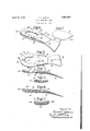
- Fig. l is a perspective view of the improved shank piece asit appears before a heelfcushioning pad has been assembled therewith;
- Fig. 2 is a ⁇ perspective viewof a heel-cushlioningpad adapted for yuse in connection with the shank piece shown in Fig. l;
- Fig. 3 is a plan view of the improved shank piece, together with the heelfoushioning pad, a portion of which is brokenaway to vdisclose certain characteristics of the pad-receiving pocket in theshank piece; n
- Fig. 4 is a sectional view taken' alongthe '75 the accompanying drawings, iny
- Fig. 5 is a sectional View taken along the line V-V of Fig. 3 showing the heel-cushioning pad in place
- Fig. 6 is a longitudinal sectional view of an alternative form of shank piece
- Fig. 7 is a transverse sectional view taken through the heel portion of the shank piece shown in Fig. 6.
- the shank piece shown in Figs. 1 to 5, inclusive comprises:
- a filler member 10 made of suitable nonmetallic material such as leather or leather- 'I board and a metallic stifener strip 12 (Fig.
- the filler member 10 is shaped in marginal contour to correspond to the marginal contour of the heel and shank portions of the bottom of a shoe.
- the margins of the filler member 10 are shown as being: reduced or The construction so far described: is similar to that of the-usual shank pieces used in turn shoes although the present shankl piece is adapted for use between the inner andy outer Soles of aV double soled shoe, as Well as for use in a turn shoe.
- a heel cushioning pad such as the pad 16- showny in Fig. 2,r a cupped recess or pocket 18fis provided at the upper side of the filler member 10-by assembling with the-filler member two curved strips 20, which, are, Wedgeshaped in cross-section, and a supplementary filler piece 22.
- the strips-20 may conveniently be formed by bending two strips ofstock.
- Horseshoe rands such as are ordinarily employed in the manufacture of leather heels.
- the supplementary filler piece 22 is secured to the shank portion ofv the main filler member 10 in front of the strips 20 and is shaped to conform to the marginal contour of the main filler member.
- the thickness of the filler piece 22 corresponds to the combined thickness ofthe tivo stripsQ() at the rear er.- tremity of the member 2.2 but the thickness of the filler piece 22 diminishes gradually toward its front extremity .26 which red uccd substantially to a featherV edge so that and the portion, of the filler member 10' upper surface Will blend with the upper surface of the main filler member 10.
- the rear edge of the supplementary measure is substantially perpendicular to the surface of the member 10 and closely abuts the square front edges of the rand-shaped members Q0, as indicated at 28, and provides an abrupt shoulder 30, best shown in Fig.
- the member Q2 may be secured tothe member l0 by adhesive, supplemented, as shown, by means of tacks 3i.
- the pad-receiving pocket 180- is formed; by attaching to the main filler member of the shank piece a single layer of material 200 theA upper surface of which has been gouged toprovide the desired concavity for the reception of the pad.
- the front Wall of the pocket 180 is defined by the rear edge of the supplementary filler piece 22.
- rEhe heel-cushioning pad 16 may be com.- posed. of'soft rubber or other-'suitable yielding material andy the pad may be secured by any suitable means within the pocket in the shank piece.
- the concavity of the pocket in the shank piece and the corresponding convexity of thel'ower'sideof the pad 16 are such that, the pad is more yielding and resilient inv its central than along its rear and lateral margins. Consequently the pad is readily conformableunder the pressure ofthe foot to afford the desircd'cuppedheel supporting surface which Will effectively, though yieldingly, support the marginal as well as the central portions ofthe bottom of the heel of the foot.
- the above-described shank piece is adapt ed for use between the inner and outer soles of double soled shoes such, for example, as weltshoes, McKay-sewed shoes, or shoes in which the outsoleis secured in placey by cement, in any of which cases the heel-cushion,- ing pad is separated from the foot by only a relatively thin layer of insole material.
- the pad is practically as effective for the purpose of cushioning the heel of the foot as if it were arranged for direct engagementwith the foot.
- the above-described shank piece is applied to the inner' surface of the sole, in the same Way as a so-called turn shank piece is ordinarily applied, and the cushioning pad' maybe left uncovered for direct engagement with the heel of the foot, or, if desiredhthe pad may be covered by the usual sock lining.
- a shank piece having a rear portion adapted to extend above the heel of a shoe and having a cupped recess therein for receiving a heel-cushioning pad, the shank piece being formed with an abrupt shoulder extending throughout its width and located forwardly of said pocket for engaging the front of a pad seated inthe pocket.
- a shankpiece comprising a body member, and means securedto the body member and constructed and arranged to provide a pocket for receiving aheel-cushioning pad and also to provide a surface sloping from the margin of the pocket toward the bottom thereof and blending gradually with the upper surface of the body portion of the shank piece.
- shank piece comprising a body kportion, a wedge-shaped member secured to the upper surface of the body portion and arranged to provide a substantially perpendicular shoulder extending transversely across i the. shank piece, and ia surface sloping forrWardly from said shoulder, and means secured to the upper side of said body member at the rear of said wedge-shapedmember shaped to provide arcup-shaped recess for f receiving a heel-cushioning pad.
- a shank piece comprising a member having a marginal contour corresponding to that ofthe heel and lshank portions of the bottom of a shoe, and means secured to the upper side of said member constructed and arranged to provide a cupped recess forreceiving a heel-cushioning pad and an abutment forv engaging the front edge of the pad.
- a shank piece comprising a member having a marginal contour corresponding to that ofthe heel and shank portions of thebottom member secured :to the uppersurface of said body member and shaped and arranged to ⁇ provide a pocketl for receiving ya heel-cushioning pad, said pocket having a substantially perpendicular front wallfor preventing forward displacement' of the'pad.
- a shank piece comprising a member having a marginal contour corresponding to that of the bottom of the heel and shank portions of a shoe, and means including a strip wedge-shaped in cross-section throughout its entire width secured to the upper surface of said memberand extending along the margin yofthe heel portion thereof to form a concavity at the upper side of saidy member extending to the extreme outer edge thereof for receiving a heel-cushioning pad.
- a shank piece comprising a member having a marginal contour corresponding to that of the bottom of the heel and shank portions of a shoe, and a plurality ⁇ of rand# f shaped strips arranged in superposed relation and secured to said member, said strips extending along the margin of the heel portion of said member and being arranged with their thin edges innermost to provide a pocket for ⁇ receiving a heel-cushioning pad, and means secured to said member in front of said strips to-engage said pad to prevent forward displacement thereof.
- a shank piece comprising a member havinga marginal contour corresponding ⁇ to that of the bottom of the heel and shank portions of a shoe, and a plurality of randshaped strips arranged in superposed relation and secured to said member, said strips extending along the margin of the heel portion of said member and being arranged with their thin edges innermost to provide a pocket for receiving a heel-cushioning pad, and a fillerA piece secured to the shank portion of said member, said filler piece abutting the for.
- a shank piece for a turn shoe comprising a main filler member having a marginal contour shaped to correspond to that of the heel and shankport'ions of the bottom of a shoe and having a concave upper surface, and
Description
April 12, 1932. l 0, C, ADAMS 1,853,027
SHANK PIECE FOR SHOES Filed April 29, 1930 Y /M/E/v ma Patented Apr. 1,2, i932.
UNITED sfr-'Ares v*PfaffENTff orar f y i aasaez'zf oscAR c. ADAMS, on LYNN, MASSACHUSETTS, Ass'IGNoRyfro UNrrEzo SHOE MACHINERY y CORPORATION, 0F. PANIER/SON, N JER SHANK PIECE FOR SHOESv Application led April 29, 1930. iSerial No. 448,357.
YThis invention relates to improvements in shank pieces for shoes and, as herein illus-k trated, is embodied in a shank piece especially designed for usein a shoe having an inter-k nal heel cushion. f l
It has been customary heretofore, in certainv types of cushion heel shoes, to provide a pocket or cavity in the rear yportion of the insole and tok insert a cushionor padin this pocket to afford a yielding supporty for the heel of the foot. 1 Such a construction, how.- ever, has not provedto be .entirely satisfactory from the standpoint of good shoemaking and, moreover, the necessity'of forming a cushion- :receiving pocket in theinsole has added ma-y terially to the labor and expense of manufacturing such shoes.- y
In'view of the foregoing, one object of the present invention kis toV improve the construc-k tion andreduce the expense of manufacturing shoes having' internal heel cushions.
To the accomplishmentof this object'there haslbeen vproduced'an improved articlek of manufacture Yadapted for application to the J interior of a turn shoe or for use between the soles of a'double soled shoe and consisting of a shank piece having a pocket in-its rear porf tionffor receivinga heel cushioning pad and vhaving `an .n abrupt shoulder extending throughout the width of the shank piece Vand located forwardly of the pocket for engagin the yfront of a pad seated in the pocket to hold the pad against forwardI displacement in the shoe. Y
E" The shank piece herein shown4 comprises a f ller member having Va marginal contour correspondingto that of the `heel and shank por# tions'of` the bottom of ashoe, the filler member beinglongitudinallv arched forwardly of its v*heel portion and provided with a metallic stiifeningjand reinforcing strip which is curved'to maintain the longitudinali arch of theller member. As illustrated, the padreceiving pocket is a shallow concavity formed bythe attachment to the upper sur-y 'face of the filler member of two strips which ranged one above the other, the strips being sEYaAooRronA'rroN on NEW JERSEY A are wedge-shaped in cross-section and are arcurved to correspond to the curvature of the f lliargin of theheel portion of the filler memer. forward displacement ofthe pad is formed by the rear edge of a supplementary filler` ypiece which is secured to the main filler memf The'illustrated shoulder for preventing iit the bottom contour of the pocket in the shank piece andy/has a forwardedge facel which engages the rear edgeof the supplementary filler piece.
The illustrated shank piece, while especlally designed for application to a turn shoe,
is also adapted for yuse between the soles of double soled shoe, in which case the cushioning pad will be effective to alford yielding support for the heel of the'foot notwithstanding ythe fact that theinsole is between the pad and the foot. When yused in a turn shoe, however, the pad may be permitted to come into direct engagement with 4the footv or it;y
may be covered merely by means of a suitable sock lining.
The invention will be explained with referwhich Fig. l is a perspective view of the improved shank piece asit appears before a heelfcushioning pad has been assembled therewith;
Fig. 2 is a `perspective viewof a heel-cushlioningpad adapted for yuse in connection with the shank piece shown in Fig. l;
Fig. 3 is a plan view of the improved shank piece, together with the heelfoushioning pad, a portion of which is brokenaway to vdisclose certain characteristics of the pad-receiving pocket in theshank piece; n
Fig. 4 is a sectional view taken' alongthe '75 the accompanying drawings, iny
line IV-IV of Fig. 3, the heel-cushioning pad not being shown;
Fig. 5 is a sectional View taken along the line V-V of Fig. 3 showing the heel-cushioning pad in place g Fig. 6 is a longitudinal sectional view of an alternative form of shank piece; and
Fig. 7 is a transverse sectional view taken through the heel portion of the shank piece shown in Fig. 6.
Referring to the drawings, the shank piece shown in Figs. 1 to 5, inclusive, comprises:
a filler member 10 made of suitable nonmetallic material such as leather or leather- 'I board and a metallic stifener strip 12 (Fig.
4) which is secured at its ends to the filler member 10 by means such as the tacks 1l.. The filler member 10 is shaped in marginal contour to correspond to the marginal contour of the heel and shank portions of the bottom of a shoe. The margins of the filler member 10 are shown as being: reduced or The construction so far described: is similar to that of the-usual shank pieces used in turn shoes although the present shankl piece is adapted for use between the inner andy outer Soles of aV double soled shoe, as Well as for use in a turn shoe.
In order to provide for the reception. of
a heel cushioning pad, such as the pad 16- showny in Fig. 2,r a cupped recess or pocket 18fis provided at the upper side of the filler member 10-by assembling with the-filler member two curved strips 20, which, are, Wedgeshaped in cross-section, and a supplementary filler piece 22., The strips-20 may conveniently be formed by bending two strips ofstock.
c of the re uired tapering cross-sectional shape into con ormity with the edge curvature of the heel portion of the filler member 10.A
Horseshoe rands, such as are ordinarily employed in the manufacture of leather heels.,
may advantageously be employed to constitute the strips 20, t-he rands being secured together and attached to the filler member 10 by the use of adhesive supplemented, if desired, by means of tacks or nails 24. The supplementary filler piece 22 is secured to the shank portion ofv the main filler member 10 in front of the strips 20 and is shaped to conform to the marginal contour of the main filler member. The thickness of the filler piece 22 corresponds to the combined thickness ofthe tivo stripsQ() at the rear er.- tremity of the member 2.2 but the thickness of the filler piece 22 diminishes gradually toward its front extremity .26 which red uccd substantially to a featherV edge so that and the portion, of the filler member 10' upper surface Will blend with the upper surface of the main filler member 10. The rear edge of the supplementary pietre is substantially perpendicular to the surface of the member 10 and closely abuts the square front edges of the rand-shaped members Q0, as indicated at 28, and provides an abrupt shoulder 30, best shown in Fig. al, for engagement with the front edge face 32 of the cushioning pad 16 in such a manner as ellectively to prevent forward displacement of the pad Within the shoe. The member Q2 may be secured tothe member l0 by adhesive, supplemented, as shown, by means of tacks 3i.
As a result of the above-described construction and arrangement of the rand-shaped strips 20fthe pocket or concavity 1S is shaped to fit the convex lower surface 36 of the pad 16 sol thaty when the pad 1G has been placed Within the recess 18 the upper surface of the pad will beA flush with the outer edge of the upper strip 2Ov and with the upper surface of the supplementary filler piece In the construction shown in Figs. 6 and 7, the pad-receiving pocket 180-is formed; by attaching to the main filler member of the shank piece a single layer of material 200 theA upper surface of which has been gouged toprovide the desired concavity for the reception of the pad. As in Fig. 1, the front Wall of the pocket 180 is defined by the rear edge of the supplementary filler piece 22.
rEhe heel-cushioning pad 16 may be com.- posed. of'soft rubber or other-'suitable yielding material andy the pad may be secured by any suitable means within the pocket in the shank piece.
The concavity of the pocket in the shank piece and the corresponding convexity of thel'ower'sideof the pad 16 are such that, the pad is more yielding and resilient inv its central than along its rear and lateral margins. Consequently the pad is readily conformableunder the pressure ofthe foot to afford the desircd'cuppedheel supporting surface which Will effectively, though yieldingly, support the marginal as well as the central portions ofthe bottom of the heel of the foot.
The above-described shank piece is adapt ed for use between the inner and outer soles of double soled shoes such, for example, as weltshoes, McKay-sewed shoes, or shoes in which the outsoleis secured in placey by cement, in any of which cases the heel-cushion,- ing pad is separated from the foot by only a relatively thin layer of insole material. Thus the pad is practically as effective for the purpose of cushioning the heel of the foot as if it were arranged for direct engagementwith the foot. lVhen used in a turn shoe, however, the above-described shank piece is applied to the inner' surface of the sole, in the same Way asa so-called turn shank piece is ordinarily applied, and the cushioning pad' maybe left uncovered for direct engagement with the heel of the foot, or, if desiredhthe pad may be covered by the usual sock lining.
Having described my invention, what I claim as new and desire to secure by Letters Patent of the United States is :V
l. A shank piece having a rear portion adapted to extend above the heel of a shoe and having a cupped recess therein for receiving a heel-cushioning pad, the shank piece being formed with an abrupt shoulder extending throughout its width and located forwardly of said pocket for engaging the front of a pad seated inthe pocket.
receiving a heel-cushioning pad, and a mem-4 ber secured to the shank piece forwardlyk of the pocket andv constructed and arranged to provide an abrupt shoulder for engaging the front of a heel-cushioning pad in the pocket, said member having a forwardly sloping upper surface arranged to blend gradually with theupper surface of the forward portion of the shankpiece.
4. A shankpiececomprising a body member, and means securedto the body member and constructed and arranged to provide a pocket for receiving aheel-cushioning pad and also to provide a surface sloping from the margin of the pocket toward the bottom thereof and blending gradually with the upper surface of the body portion of the shank piece.
5. shank piece comprising a body kportion, a wedge-shaped member secured to the upper surface of the body portion and arranged to provide a substantially perpendicular shoulder extending transversely across i the. shank piece, and ia surface sloping forrWardly from said shoulder, and means secured to the upper side of said body member at the rear of said wedge-shapedmember shaped to provide arcup-shaped recess for f receiving a heel-cushioning pad.
6'. A shank piece comprisinga member having a marginal contour corresponding to that ofthe heel and lshank portions of the bottom of a shoe, and means secured to the upper side of said member constructed and arranged to provide a cupped recess forreceiving a heel-cushioning pad and an abutment forv engaging the front edge of the pad.
'7. A shank piece comprising a member having a marginal contour corresponding to that ofthe heel and shank portions of thebottom member secured :to the uppersurface of said body member and shaped and arranged to` provide a pocketl for receiving ya heel-cushioning pad, said pocket having a substantially perpendicular front wallfor preventing forward displacement' of the'pad.
9. A shank piece comprising a member having a marginal contour corresponding to that of the bottom of the heel and shank portions of a shoe, and means including a strip wedge-shaped in cross-section throughout its entire width secured to the upper surface of said memberand extending along the margin yofthe heel portion thereof to form a concavity at the upper side of saidy member extending to the extreme outer edge thereof for receiving a heel-cushioning pad.
10. A shank piece comprising a member having a marginal contour corresponding to that of the bottom of the heel and shank portions of a shoe, and a plurality `of rand# f shaped strips arranged in superposed relation and secured to said member, said strips extending along the margin of the heel portion of said member and being arranged with their thin edges innermost to provide a pocket for `receiving a heel-cushioning pad, and means secured to said member in front of said strips to-engage said pad to prevent forward displacement thereof.
l1. A shank piece comprising a member havinga marginal contour corresponding `to that of the bottom of the heel and shank portions of a shoe, and a plurality of randshaped strips arranged in superposed relation and secured to said member, said strips extending along the margin of the heel portion of said member and being arranged with their thin edges innermost to provide a pocket for receiving a heel-cushioning pad, and a fillerA piece secured to the shank portion of said member, said filler piece abutting the for.
ward ends of said rand-shaped filler pieces and diminishing in thickness toward the forey ward portion of the shank piece.
l2. A shank piece for a turn shoe comprising a main filler member having a marginal contour shaped to correspond to that of the heel and shankport'ions of the bottom of a shoe and having a concave upper surface, and
'a supplementary filler ymember secured to said main filler member and constructed and arranged to accentuate the concavity of said isc;
sunwe tto ndzapt .it for receiving n heel-cushioning pad.
18. .A .shank .piece .for'fmturnshoe compnising a :main filler kmember having 'u :marginal contour `shaped to correspond to :that offthe heel yand shank portions of the bottom of Aa shoe Vund having a. `concave upper surface, .a supplementary filler member secured to said main iiller member and constructed fana arranged to Yaccentuate vthe concavity of said sul'. :we :to adapt Vit for receiving av heel-.cushion'mg zpad, und a met-aillicstiencr stvip `segred to the flower surface-offsaid filler zmem- In ytestimony `whereod. I have .signed my name to this specification.
OSCAR C. ADAMS.
Priority Applications (1)
| Application Number | Priority Date | Filing Date | Title |
|---|---|---|---|
| US448357A US1853027A (en) | 1930-04-29 | 1930-04-29 | Shank piece for shoes |
Applications Claiming Priority (1)
| Application Number | Priority Date | Filing Date | Title |
|---|---|---|---|
| US448357A US1853027A (en) | 1930-04-29 | 1930-04-29 | Shank piece for shoes |
Publications (1)
| Publication Number | Publication Date |
|---|---|
| US1853027A true US1853027A (en) | 1932-04-12 |
Family
ID=23779986
Family Applications (1)
| Application Number | Title | Priority Date | Filing Date |
|---|---|---|---|
| US448357A Expired - Lifetime US1853027A (en) | 1930-04-29 | 1930-04-29 | Shank piece for shoes |
Country Status (1)
| Country | Link |
|---|---|
| US (1) | US1853027A (en) |
Cited By (4)
| Publication number | Priority date | Publication date | Assignee | Title |
|---|---|---|---|---|
| US5187883A (en) * | 1990-08-10 | 1993-02-23 | Richard Penney | Internal footwear construction with a replaceable heel cushion element |
| US5435077A (en) * | 1994-04-18 | 1995-07-25 | The United States Shoe Corporation | Layered cushioning system for shoe soles |
| EP2080442A1 (en) * | 2008-01-15 | 2009-07-22 | Mascot International A/S | Shoe or safety shoe or safety boot and multifunctional shank |
| EP2299862A1 (en) * | 2008-07-05 | 2011-03-30 | Ecco Sko A/S | Sole for a shoe, in particular for a running shoe |
-
1930
- 1930-04-29 US US448357A patent/US1853027A/en not_active Expired - Lifetime
Cited By (6)
| Publication number | Priority date | Publication date | Assignee | Title |
|---|---|---|---|---|
| US5187883A (en) * | 1990-08-10 | 1993-02-23 | Richard Penney | Internal footwear construction with a replaceable heel cushion element |
| US5435077A (en) * | 1994-04-18 | 1995-07-25 | The United States Shoe Corporation | Layered cushioning system for shoe soles |
| EP2080442A1 (en) * | 2008-01-15 | 2009-07-22 | Mascot International A/S | Shoe or safety shoe or safety boot and multifunctional shank |
| EP2299862A1 (en) * | 2008-07-05 | 2011-03-30 | Ecco Sko A/S | Sole for a shoe, in particular for a running shoe |
| EP2299862A4 (en) * | 2008-07-05 | 2013-05-29 | Ecco Sko As | Sole for a shoe, in particular for a running shoe |
| US10165821B2 (en) | 2008-07-05 | 2019-01-01 | Ecco Sko A/S | Sole for a shoe, in particular for a running shoe |
Similar Documents
| Publication | Publication Date | Title |
|---|---|---|
| US3416245A (en) | Contoured insole | |
| US1807341A (en) | Cushioning insole for boots and shoes | |
| US2070116A (en) | Arch-supporting shoe | |
| US1550715A (en) | Shoe insole | |
| US3086301A (en) | Shoe construction | |
| US1853027A (en) | Shank piece for shoes | |
| US2027072A (en) | Sock lining for shoes | |
| US2442007A (en) | Shoe with shank spring and stiffener | |
| US2157818A (en) | Shoe | |
| US1996215A (en) | Foot corrective shoe construction | |
| US2322297A (en) | Shoe | |
| US2099394A (en) | Shank stiffener | |
| US2208822A (en) | Lady's shoe | |
| US2938284A (en) | Shoe with cushion foundation | |
| US2111666A (en) | Flexible arch supporting sole | |
| US2188225A (en) | Shoe construction | |
| US1942001A (en) | Shoe | |
| US1745627A (en) | Shoe construction | |
| US2300739A (en) | Insole | |
| US2343790A (en) | Shoe inner sole | |
| US1995506A (en) | Shoe | |
| US2318846A (en) | Shoe and method of making same | |
| US2301345A (en) | Last for making shoes | |
| US2317918A (en) | Inner sole for welt shoes | |
| US1285426A (en) | Shoe. |