US1853025A - Cowling fastener - Google Patents
Cowling fastener Download PDFInfo
- Publication number
- US1853025A US1853025A US461501A US46150130A US1853025A US 1853025 A US1853025 A US 1853025A US 461501 A US461501 A US 461501A US 46150130 A US46150130 A US 46150130A US 1853025 A US1853025 A US 1853025A
- Authority
- US
- United States
- Prior art keywords
- cam
- cavity
- pin
- fastening
- arm
- Prior art date
- Legal status (The legal status is an assumption and is not a legal conclusion. Google has not performed a legal analysis and makes no representation as to the accuracy of the status listed.)
- Expired - Lifetime
Links
- 230000000717 retained effect Effects 0.000 description 4
- 238000007689 inspection Methods 0.000 description 3
- 239000002184 metal Substances 0.000 description 3
- 238000010276 construction Methods 0.000 description 2
- 238000005452 bending Methods 0.000 description 1
- 230000014759 maintenance of location Effects 0.000 description 1
- 230000011514 reflex Effects 0.000 description 1
Images
Classifications
-
- F—MECHANICAL ENGINEERING; LIGHTING; HEATING; WEAPONS; BLASTING
- F16—ENGINEERING ELEMENTS AND UNITS; GENERAL MEASURES FOR PRODUCING AND MAINTAINING EFFECTIVE FUNCTIONING OF MACHINES OR INSTALLATIONS; THERMAL INSULATION IN GENERAL
- F16B—DEVICES FOR FASTENING OR SECURING CONSTRUCTIONAL ELEMENTS OR MACHINE PARTS TOGETHER, e.g. NAILS, BOLTS, CIRCLIPS, CLAMPS, CLIPS OR WEDGES; JOINTS OR JOINTING
- F16B5/00—Joining sheets or plates, e.g. panels, to one another or to strips or bars parallel to them
- F16B5/10—Joining sheets or plates, e.g. panels, to one another or to strips or bars parallel to them by means of bayonet connections
-
- Y—GENERAL TAGGING OF NEW TECHNOLOGICAL DEVELOPMENTS; GENERAL TAGGING OF CROSS-SECTIONAL TECHNOLOGIES SPANNING OVER SEVERAL SECTIONS OF THE IPC; TECHNICAL SUBJECTS COVERED BY FORMER USPC CROSS-REFERENCE ART COLLECTIONS [XRACs] AND DIGESTS
- Y10—TECHNICAL SUBJECTS COVERED BY FORMER USPC
- Y10T—TECHNICAL SUBJECTS COVERED BY FORMER US CLASSIFICATION
- Y10T24/00—Buckles, buttons, clasps, etc.
- Y10T24/45—Separable-fastener or required component thereof [e.g., projection and cavity to complete interlock]
- Y10T24/45225—Separable-fastener or required component thereof [e.g., projection and cavity to complete interlock] including member having distinct formations and mating member selectively interlocking therewith
- Y10T24/45602—Receiving member includes either movable connection between interlocking components or variable configuration cavity
- Y10T24/45623—Receiving member includes either movable connection between interlocking components or variable configuration cavity and operator therefor
- Y10T24/45639—Receiving member includes either movable connection between interlocking components or variable configuration cavity and operator therefor including pivotally connected element on receiving member
-
- Y—GENERAL TAGGING OF NEW TECHNOLOGICAL DEVELOPMENTS; GENERAL TAGGING OF CROSS-SECTIONAL TECHNOLOGIES SPANNING OVER SEVERAL SECTIONS OF THE IPC; TECHNICAL SUBJECTS COVERED BY FORMER USPC CROSS-REFERENCE ART COLLECTIONS [XRACs] AND DIGESTS
- Y10—TECHNICAL SUBJECTS COVERED BY FORMER USPC
- Y10T—TECHNICAL SUBJECTS COVERED BY FORMER US CLASSIFICATION
- Y10T24/00—Buckles, buttons, clasps, etc.
- Y10T24/45—Separable-fastener or required component thereof [e.g., projection and cavity to complete interlock]
- Y10T24/45225—Separable-fastener or required component thereof [e.g., projection and cavity to complete interlock] including member having distinct formations and mating member selectively interlocking therewith
- Y10T24/45602—Receiving member includes either movable connection between interlocking components or variable configuration cavity
- Y10T24/45775—Receiving member includes either movable connection between interlocking components or variable configuration cavity having resiliently biased interlocking component or segment
- Y10T24/45822—Partially blocking separate, nonresilient, access opening of cavity
Definitions
- My invention relates to fastening devices, and is particularly suitable for use in removably securing metal cowling, inspection plates, and the like to the framework or structure of an aeroplane.
- Cowling, inspection plates, or other removable portions of the covering of a;metal aeroplane be normally securely held in place but be quickly and easily removable when desired.
- aeroplanes as it may be used to advantage in numerous other embodiments.
- Another object of my invention is to provide a device in which the cooperating parts of the locking mechanism included therei are relatively adjustable.
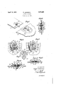
- Fig. 1 l is a perspective view of a primary Fig. 5 is a sectional view taken as indicated by the line 5--5 of Fig. 2.
- Fig. 6 is a sectional view taken as indicated by the line 6 6 of Fig. 3.
- Fig. 7 is an elevational view of the locking mem er of my device.
- Fig. 1 I show a primary body 11 which may be a section of the frame or structure of an aeroplane, and a secondary body 12 which may be a section of a Cowling strip or plate covering certain parts of the frame 11.
- a slot 13 for the adjustable retention of a locking ⁇ pin generally designated by the numeral 14.
- the pin 14 is formed with a threaded shank portion 15 andhas an enlarged mushroomshaped knob portion 16 on the upper end.
- Anfannular groove 17 is cut in the shank portion l5, thus forming a collar 18, said collar being relatively larger than the threaded portion 15.
- the threaded portion 15 is adapted to extend,l through the slot 13 and to receive a friction washer 19 and a nut 20, the nut 20 being operable to clamp the wall 21 of the body 11 between the collar 18 of the pin 14 and the friction washer 19.
- a locking pin 22 may be used to lock the nut 20 in position as shown in Fig. 4. It will be seen that the locking pin 14 is adjustable in the slot 13 inthe directions indicated by the double ar- ⁇ row 25 of Fig. 1.
- a shallow U-sha ed depression 30 adapte to receive the locking mechanism of the inven tion, whichis generally indicated by the numeral 31.
- the mechanism 31 is supported Within the recess 30 by a lock housing 35 having the form of an open ended rectangular dish comprising a bottom Wall 36 and vertical side walls 37, the upper portions of which are bent horizontally outward to form flanges 38.
- the housing 35 is secured to the wall 39 of the body 12 Within the depression 30 by rivets 40.
- Both of the openings 45 and 46 are elongated in a direction at right angles to the axis of the slot 13 in the body 11.
- the locking means of the invention comrises 'a spring wire member generally designated by the numeral 50, which may be formed as shown in Fig. 7 by first bending a suitable length of spring wire in the form of an isosceles triangle, having a base 51 and sides 52 and 53. At a suitable point,
- the sides 52 and 53 are bent in a substantially reverse direction so that the extremities 55 and 56 thereof extend convergently toward the base 51 as shown in Fig. 7.
- the end portions and 56 are extended within the housing 35 at one end thereof, the sides 52 and 53 being extended along the exterior of the housing and the base portion 51 being positioned in frictional contact with the opposite end thereof under a lip 58 which projects outwardly as an extension of the wall 36.
- an opening 60,v which is axially aligned with an opening 61 in the wall 39, these openings and 61 being also in alignment relative to the axis A--A as shown in Fig. 2.
- an operating member 63 Positioned within the openings 60 and 61 and Y conforming closely to the diameter thereof is an operating member 63 which is of such a thickness that the top and bottom surfaces u thereof are flush with the outer surfaces of the wall 39 and the wall 36 respectively.
- member 63 Extending entirely around the circumference of the, member 63 is a cam groove 65, the bottom of which forms a cam surface 66 providing a pair of diametrically opposite high spots 67, and a pair of diametrically opposite low spots 68 as illustratedby dotted lines in Figs. 2 and 3.
- a screw driver slot 70 is provided, which slot is adapted to be engaged by a suitable instrument for the manual rotation' of the member 63.
- the free end portions 55 and 56 of thel operating member in place.
- the operating member is prevented from axial movement from the housing in which it is located through either of the openings 60 or 61 by reason of the fact that one or both of the arms of the spring member 50 extend into the groove 65 and thus prevent the removal of the operating member 63. If it is desired to remove the operating member 63, this may be easily accomplished by spreading the arms of the spring member 50 so that they are moved entirely out of the groove 65.
- the operating member 63 When it is desired to release the body 12 from engagement with the body 11, the operating member 63 is rotated through 90 in either direction, causing the high spots 67 to force the end portions 55 and 56 of the spring member 50 into the position shown in Fig. 2, permitting the withdrawal of the pin 14 from the openings 45 and 46.
- a further important feature of my present invention is the details of construction of the operating member 63 and the' manner in which itis retained in place.
- the operating member 63 may be very easily inserted into operating position after the other parts of the device have been assembled. It will be noted that the only securement which is required inthe preferred form of my invention, for retaining the operating member 63 in place, is that one or both of the arms of the spring member 50 rest in the groove 65.
- a further important feature of my invention is the manner in which the locking pin and the locking device are adjustable relative to each other in order that alignment may be obtained. It will be noted that in Fig. ⁇ 1 the slot 13 through which the locking pin 14 extends is elongated on an axis which is at right angles to the axis of the opening 45.
- a fastening device the combination of: a primary member having a primary slot formed therein'; a fastening pin secured to said primary member and being adjustable in sald primary slot; a secondary member.
- I having a secondary slot formed therein, said secondary slot being elongated at an angle to the major axis of said 'primary slot, said fastening pin being adapted to project into said secondary slot; and locking means for lzlicking said fastening pin in said secondary s ot.
- a fastening device the combination of: a primary member having a primary slot formed therein; a fastening pin secured to said primary member and being adjustable in said primary slot; a secondary member having a secondary slot formed therein, said secondary slot being elongated at right angles to the major axis of said primary slot, said fastening pin being adapted to project into said secondary slot; and locking means for kicking said fastening pin in said secondary s ot.
- a fastening device the combination of: walls forming a cavity Aand an opening through which a fastening pin may be inserted in said cavity; spring means having a spring arm extending adjacent said opening so as to be capable of engaging the fastening pin; and cam means in said cavity and being exposed through an aperture in said walls, said cam means engaging saidspring means and being operable to move said arm into nonengaging position, and said cam means being retained in place solely by reason of its engagement Withsaid spring means.
- a fastening device the combination of: Walls forming a cavity having an opening through which a fastening pin may extend into said cavity and having an aperture; lock means in said cavity having an arm capable of engaging the fastening pin when same is extended in said cavity; and cam means extending through said aperture and into said cavity, said cam means having a'cam groove formed therein through which said. arm of said lock means extends, said arm being moved into a non-engaging position upon a rotation of said cam means, andsaid lock means constituting the only means for retaining said cam means from removal from said cavity.
- a fastening device the combination of: Walls forming a cavity having an open-l ing through which a fastening pin may extend into said cavity and having a pair of y' aligned apertures; lock means in said cavity having an arm capable ofengaging the fastening pin when same is extended in said cavity; and cam means, said cam means having bearing portions journaled in said aligned apertures, and said cam .means having a cam groove formed therein in which a portion of said lock means extends, said army being moved into a non-engaging positionupon a rotation of said cam means, and ySaid lock means constituting the only means for retaining said cam means from removal from said cavity through one of saidapertures.
- a fastening device In a fastening device, the combination of: a wall having. an opening through which a fastening pin may be extended, and an aperture having a cylindrical Wall which constitutes a cylindrical bearing; a. spring means secured to said Wall and having an arm which is engageable with a fastening pin which may be extended through said opening; and a cam member having a cylindrical journal ortion which is journaled in said aperture y said cylindrical bearing, and havinga cam ortion provided with a groove through whlch said arm extends for retaining said cam member in place in said aperture, and having a cam face in the bottom of said groove whereby upon a rotation e of said cam member said arm may be moved into non-engaging position.
- a fastening device the combination of: a Wall having an' opening through which a fastening pin may be extended, and an aperture havlng a cylindrical wall which constitutes a cylindrical bearing; a spring ⁇ means secured to said wall and having an arm which is engageable with a fastenin pinl which maybe extended through said opening; and a cam member having a cylindrical )ournal portion which is journaled in said aperture by said cylindrical bearing, and having a cam portion provided with a groove through which said arm extends for retaining said cam member in place in said aperture, said spring means constituting the only means for holding said cam member in place, and having a cam face in the bottom of said groove whereby upon' a rotation of said cam member said arm may be moved into Anon-engagin position.
Description
April l2, 1932". ANDERSON 1,853,025
GOWLING FASTENER Filed June 16, 1930 A from/fx Patented Apr. 12, 1932 UNITED STATES` PivrrN'r or-Flcs ROBERT ANDERSON, F WEST LOS AITGELES, CALIFORNIA, ASSIGNOR TO DOUGLAS AIRCRAFT COMPANY, INC., 0F .SANTA'MONICL CALIFORNIA,
DELAWARE A CORPORATION 0F eowLINe 'FASTENEB Application led .Tune 16, 1930. Serial No. 461,501.
My invention relates to fastening devices, and is particularly suitable for use in removably securing metal cowling, inspection plates, and the like to the framework or structure of an aeroplane.
` It is desirable that the Cowling, inspection plates, or other removable portions of the covering of a;metal aeroplane be normally securely held in place but be quickly and easily removable when desired.
It is therefore an object of my invention to provide a fastening device which is particularly adapted to fastening metal cowling on an aeroplane, although I do'not wish to lim- 5 it the scope of my invention to utility on,
aeroplanes as it may be used to advantage in numerous other embodiments.
' It is another object of my invention to provide a device of the character described which may be quickly and easily locked or unlocked without the use of special tools.
It is another object of my invention to provide an operable device so designed as to produce va minimum of wind-resistance,
when used on an aeroplane.
It is another object of my invention to provide a device of the character described in which the locking mechanism included therein remains in open or closed position until manually operated. e
Another object of my invention is to provide a device in which the cooperating parts of the locking mechanism included therei are relatively adjustable.
It is a further object of'myl invention to provide, a locking device of the character mentioned in which the different elements are of novel construction which permit a very simplified,l cheap, and economical arrangement of parts, which nevertheless are operi ative to roduce a fastenin means which is quite satisfactory for the purpose intended.
It is an object of my invention to provide a locking device of the -character' mentioned in which the operating means is retained in place solely by the locking arm of the device. .These and yother objects will be apparent from a perusal of the following specification, the accompanying drawings, and the appended. claims.
Referring to the drawings:
Fig. 1 lis a perspective view of a primary Fig. 5 is a sectional view taken as indicated by the line 5--5 of Fig. 2.
Fig. 6 is a sectional view taken as indicated by the line 6 6 of Fig. 3.
Fig. 7 is an elevational view of the locking mem er of my device.
In Fig. 1 I show a primary body 11 which may be a section of the frame or structure of an aeroplane, and a secondary body 12 which may be a section of a Cowling strip or plate covering certain parts of the frame 11.
Provided in the primary body 11 is a slot 13 for the adjustable retention of a locking `pin generally designated by the numeral 14.
The pin 14 is formed with a threaded shank portion 15 andhas an enlarged mushroomshaped knob portion 16 on the upper end. Anfannular groove 17 is cut in the shank portion l5, thus forming a collar 18, said collar being relatively larger than the threaded portion 15. The threaded portion 15 is adapted to extend,l through the slot 13 and to receive a friction washer 19 and a nut 20, the nut 20 being operable to clamp the wall 21 of the body 11 between the collar 18 of the pin 14 and the friction washer 19. A locking pin 22 may be used to lock the nut 20 in position as shown in Fig. 4. It will be seen that the locking pin 14 is adjustable in the slot 13 inthe directions indicated by the double ar-` row 25 of Fig. 1.
Referring now to the lockingmechanism, details of which are shown in Fi s. 2 to 5 inclusive, I provide in the secon ary bod a shallow U-sha ed depression 30 adapte to receive the locking mechanism of the inven tion, whichis generally indicated by the numeral 31. The mechanism 31 is supported Within the recess 30 by a lock housing 35 having the form of an open ended rectangular dish comprising a bottom Wall 36 and vertical side walls 37, the upper portions of which are bent horizontally outward to form flanges 38. The housing 35 is secured to the wall 39 of the body 12 Within the depression 30 by rivets 40. Provided in the bottom wall 36 of the housing 35 is an elongated opening of a sufficient width to receive the knob 16 of the pin 14, this opening being coincident with an opening 46 provided in the wall 39. Both of the openings 45 and 46 are elongated in a direction at right angles to the axis of the slot 13 in the body 11.
The locking means of the invention comrises 'a spring wire member generally designated by the numeral 50, which may be formed as shown in Fig. 7 by first bending a suitable length of spring wire in the form of an isosceles triangle, having a base 51 and sides 52 and 53. At a suitable point,
i indicated by the dotted line 54, the sides 52 and 53 are bent in a substantially reverse direction so that the extremities 55 and 56 thereof extend convergently toward the base 51 as shown in Fig. 7.
In positioning the spring member relative to the housing 35, the end portions and 56 are extended within the housing 35 at one end thereof, the sides 52 and 53 being extended along the exterior of the housing and the base portion 51 being positioned in frictional contact with the opposite end thereof under a lip 58 which projects outwardly as an extension of the wall 36.
Provided in the wall 36 of the housing 35 ris an opening 60,v which is axially aligned with an opening 61 in the wall 39, these openings and 61 being also in alignment relative to the axis A--A as shown in Fig. 2. Positioned within the openings 60 and 61 and Y conforming closely to the diameter thereof is an operating member 63 which is of such a thickness that the top and bottom surfaces u thereof are flush with the outer surfaces of the wall 39 and the wall 36 respectively. Extending entirely around the circumference of the, member 63 is a cam groove 65, the bottom of which forms a cam surface 66 providing a pair of diametrically opposite high spots 67, and a pair of diametrically opposite low spots 68 as illustratedby dotted lines in Figs. 2 and 3.
In the upper surface of the member 63 a screw driver slot 70 is provided, which slot is adapted to be engaged by a suitable instrument for the manual rotation' of the member 63.
The free end portions 55 and 56 of thel operating member in place. The operating member is prevented from axial movement from the housing in which it is located through either of the openings 60 or 61 by reason of the fact that one or both of the arms of the spring member 50 extend into the groove 65 and thus prevent the removal of the operating member 63. If it is desired to remove the operating member 63, this may be easily accomplished by spreading the arms of the spring member 50 so that they are moved entirely out of the groove 65.
The operation of my invention is as follows:
With the operating member 63 in the position shown in Fig. 2 so that the free end portions 55 and 56 of the spring 50 are relatively spaced a distance slightly greater than the width of the opening 45, by contact with the high spots 67 of the cam surface 66 the body 12 is positioned over the body 11 in such a manner that the locking pin 14 extends upward through the openings 45 and 46. In this position the annular groove 17 in the pin 14 lies substantially in the same plane c as the free end portions 55 and 56 of the spring member, so that upon a rotation of the operating member 63 through 90 in either direction, these end portions will be released to move laterally into the groove 17 in the position shown in Fig. 3, thereby locking the pin 14 against movement. The cooperation of a plurality of similar fastening devices securely locks the body 12 to the body 11. i
When it is desired to release the body 12 from engagement with the body 11, the operating member 63 is rotated through 90 in either direction, causing the high spots 67 to force the end portions 55 and 56 of the spring member 50 into the position shown in Fig. 2, permitting the withdrawal of the pin 14 from the openings 45 and 46.
It is an important feature of the invention that when force is applied to the free ends '55 and 56 of the spring 50 in the directions indicated by the arrows 71 and 72 respectively, part of the reflex action occurs at the reverse curved portion 7 6 and part at the bent portions 77 at the intersection of the base 51 and the side portions 52 andy 53,. It will be seen from an inspection of Figs. 2 and 3 that this feature permits the end portions 55 and 56 to at all times lie in a position substantially parallel with the cam faces 67 or 68.
A further important feature of my present invention is the details of construction of the operating member 63 and the' manner in which itis retained in place. The operating member 63 may be very easily inserted into operating position after the other parts of the device have been assembled. It will be noted that the only securement which is required inthe preferred form of my invention, for retaining the operating member 63 in place, is that one or both of the arms of the spring member 50 rest in the groove 65.
A further important feature of my invention is the manner in which the locking pin and the locking device are adjustable relative to each other in order that alignment may be obtained. It will be noted that in Fig. `1 the slot 13 through which the locking pin 14 extends is elongated on an axis which is at right angles to the axis of the opening 45.
Although I have herein described only one complete embodiment of my invention, it should be understood that I am aware that various features thereof might be changed and numerous embodiments thereof might be devised without departing from the spirit and scope of my invention.
I claim as my invention:
1. In a fastening device, the combination of: a primary member having a primary slot formed therein'; a fastening pin secured to said primary member and being adjustable in sald primary slot; a secondary member.
I having a secondary slot formed therein, said secondary slot being elongated at an angle to the major axis of said 'primary slot, said fastening pin being adapted to project into said secondary slot; and locking means for lzlicking said fastening pin in said secondary s ot.
2. In a fastening device, the combination of: a primary member having a primary slot formed therein; a fastening pin secured to said primary member and being adjustable in said primary slot; a secondary member having a secondary slot formed therein, said secondary slot being elongated at right angles to the major axis of said primary slot, said fastening pin being adapted to project into said secondary slot; and locking means for kicking said fastening pin in said secondary s ot. e
3. In a fastening device, the combination of: walls forming a cavity Aand an opening through which a fastening pin may be inserted in said cavity; spring means having a spring arm extending adjacent said opening so as to be capable of engaging the fastening pin; and cam means in said cavity and being exposed through an aperture in said walls, said cam means engaging saidspring means and being operable to move said arm into nonengaging position, and said cam means being retained in place solely by reason of its engagement Withsaid spring means.
4. In a fastening device, thel combination of: Walls forming .a cavity and an opening through which a fastening pin may be in- Serted in said cavity; spring means having a spring arm extending adjacent said opening so as to be capable of engaging the fastening pin; and cam means in said cavity and being exposed through an aperture insaid Walls, said cam means having a groove in which said spring means rests and being operable to move said arm into non-engaging position, and said cam means being retained in place solely by reason of its engagement with said lspring means.
5, In al fastening device,-the combination of: Walls forming a cavity having an opening through Which a fastening pin may extend into said cavity and having an aperture; lock means in said'lcavity having an arm capable of engaging the fastening pin when same is extended in said cavity; and cam means extending through said aperture and into saidcavity, said cam means having a cam groove formed therein in which a portion of said lockmeans extends, said arm being moved into a non-engaging position upon a rotation of said cam means, and said lock means constituting the only means for retaining said cam means from removal from said cavity.
6. In a fastening device, the combination of: Walls forming a cavity having an opening through which a fastening pin may extend into said cavity and having an aperture; lock means in said cavity having an arm capable of engaging the fastening pin when same is extended in said cavity; and cam means extending through said aperture and into said cavity, said cam means having a'cam groove formed therein through which said. arm of said lock means extends, said arm being moved into a non-engaging position upon a rotation of said cam means, andsaid lock means constituting the only means for retaining said cam means from removal from said cavity.
7. In a fastening device, the combination of: Walls forming a cavity having an open-l ing through which a fastening pin may extend into said cavity and having a pair of y' aligned apertures; lock means in said cavity having an arm capable ofengaging the fastening pin when same is extended in said cavity; and cam means, said cam means having bearing portions journaled in said aligned apertures, and said cam .means having a cam groove formed therein in which a portion of said lock means extends, said army being moved into a non-engaging positionupon a rotation of said cam means, and ySaid lock means constituting the only means for retaining said cam means from removal from said cavity through one of saidapertures. A. 8. In a fastening device, the combination of: a wall having. an opening through which a fastening pin may be extended, and an aperture having a cylindrical Wall which constitutes a cylindrical bearing; a. spring means secured to said Wall and having an arm which is engageable with a fastening pin which may be extended through said opening; and a cam member having a cylindrical journal ortion which is journaled in said aperture y said cylindrical bearing, and havinga cam ortion provided with a groove through whlch said arm extends for retaining said cam member in place in said aperture, and having a cam face in the bottom of said groove whereby upon a rotation e of said cam member said arm may be moved into non-engaging position.
9. In a fastening device, the combination of: a Wall having an' opening through which a fastening pin may be extended, and an aperture havlng a cylindrical wall which constitutes a cylindrical bearing; a spring` means secured to said wall and having an arm which is engageable with a fastenin pinl which maybe extended through said opening; and a cam member having a cylindrical )ournal portion which is journaled in said aperture by said cylindrical bearing, and having a cam portion provided with a groove through which said arm extends for retaining said cam member in place in said aperture, said spring means constituting the only means for holding said cam member in place, and having a cam face in the bottom of said groove whereby upon' a rotation of said cam member said arm may be moved into Anon-engagin position.
In testimony w ereof, I have hereunto set my hand at Santa'Monica, California, this 5t day of June, 1930. ROBERT ANDERSON.
Priority Applications (1)
| Application Number | Priority Date | Filing Date | Title |
|---|---|---|---|
| US461501A US1853025A (en) | 1930-06-16 | 1930-06-16 | Cowling fastener |
Applications Claiming Priority (1)
| Application Number | Priority Date | Filing Date | Title |
|---|---|---|---|
| US461501A US1853025A (en) | 1930-06-16 | 1930-06-16 | Cowling fastener |
Publications (1)
| Publication Number | Publication Date |
|---|---|
| US1853025A true US1853025A (en) | 1932-04-12 |
Family
ID=23832804
Family Applications (1)
| Application Number | Title | Priority Date | Filing Date |
|---|---|---|---|
| US461501A Expired - Lifetime US1853025A (en) | 1930-06-16 | 1930-06-16 | Cowling fastener |
Country Status (1)
| Country | Link |
|---|---|
| US (1) | US1853025A (en) |
Cited By (3)
| Publication number | Priority date | Publication date | Assignee | Title |
|---|---|---|---|---|
| US2688173A (en) * | 1951-09-17 | 1954-09-07 | Nels E Nelson | Separable snap fastener |
| US2896287A (en) * | 1956-11-20 | 1959-07-28 | Samuel E Stultz | Separable and reversible snap fastener |
| US3041093A (en) * | 1960-01-08 | 1962-06-26 | Gen Motors Corp | Windshield wiper arm attachment |
-
1930
- 1930-06-16 US US461501A patent/US1853025A/en not_active Expired - Lifetime
Cited By (3)
| Publication number | Priority date | Publication date | Assignee | Title |
|---|---|---|---|---|
| US2688173A (en) * | 1951-09-17 | 1954-09-07 | Nels E Nelson | Separable snap fastener |
| US2896287A (en) * | 1956-11-20 | 1959-07-28 | Samuel E Stultz | Separable and reversible snap fastener |
| US3041093A (en) * | 1960-01-08 | 1962-06-26 | Gen Motors Corp | Windshield wiper arm attachment |
Similar Documents
| Publication | Publication Date | Title |
|---|---|---|
| US2861618A (en) | Fastening device with independent prehardened thrust resistant wire clips | |
| US2398220A (en) | Toggle lock | |
| US2095271A (en) | Fastening means | |
| US2390752A (en) | Fastening device | |
| US2168721A (en) | Bolt fastening device and the like | |
| US2252286A (en) | Cowl fastener | |
| US2336153A (en) | Fastening device | |
| US3389735A (en) | Retainer assembly | |
| US2295685A (en) | Sheet metal nut or the like | |
| US2398827A (en) | Cowl fastener | |
| US2873496A (en) | Fastener | |
| US1853025A (en) | Cowling fastener | |
| US2378684A (en) | Lock nut | |
| US3222744A (en) | Panel fastener | |
| US3049369A (en) | Fastening device | |
| USRE19452E (en) | Cotter key | |
| US1913555A (en) | Cotter pin | |
| US2183085A (en) | Snap fastener | |
| US2204829A (en) | Fastening device | |
| US2014971A (en) | Snap fastener stud | |
| US2560518A (en) | Friction nut | |
| US2567902A (en) | Fastener member | |
| US3052148A (en) | Ball detent fastener with ball and socket plunger assembly | |
| US2572588A (en) | Blind assembly nut | |
| US2363006A (en) | Nut and bolt socket fastening |