US1852999A - Flow detector - Google Patents
Flow detector Download PDFInfo
- Publication number
- US1852999A US1852999A US1852999DA US1852999A US 1852999 A US1852999 A US 1852999A US 1852999D A US1852999D A US 1852999DA US 1852999 A US1852999 A US 1852999A
- Authority
- US
- United States
- Prior art keywords
- valve
- flow
- water
- flow detector
- casing
- Prior art date
- Legal status (The legal status is an assumption and is not a legal conclusion. Google has not performed a legal analysis and makes no representation as to the accuracy of the status listed.)
- Expired - Lifetime
Links
- XLYOFNOQVPJJNP-UHFFFAOYSA-N water Substances O XLYOFNOQVPJJNP-UHFFFAOYSA-N 0.000 description 38
- 230000002950 deficient Effects 0.000 description 12
- 230000015572 biosynthetic process Effects 0.000 description 6
- 238000005755 formation reaction Methods 0.000 description 6
- 239000011521 glass Substances 0.000 description 6
- 206010022114 Injury Diseases 0.000 description 4
- 238000010276 construction Methods 0.000 description 4
- 239000002184 metal Substances 0.000 description 4
- QVRVXSZKCXFBTE-UHFFFAOYSA-N N-[4-(6,7-dimethoxy-3,4-dihydro-1H-isoquinolin-2-yl)butyl]-2-(2-fluoroethoxy)-5-methylbenzamide Chemical compound C1C=2C=C(OC)C(OC)=CC=2CCN1CCCCNC(=O)C1=CC(C)=CC=C1OCCF QVRVXSZKCXFBTE-UHFFFAOYSA-N 0.000 description 2
- 238000009825 accumulation Methods 0.000 description 2
- 238000007689 inspection Methods 0.000 description 2
- 238000009434 installation Methods 0.000 description 2
- 239000007788 liquid Substances 0.000 description 2
Images
Classifications
-
- F—MECHANICAL ENGINEERING; LIGHTING; HEATING; WEAPONS; BLASTING
- F16—ENGINEERING ELEMENTS AND UNITS; GENERAL MEASURES FOR PRODUCING AND MAINTAINING EFFECTIVE FUNCTIONING OF MACHINES OR INSTALLATIONS; THERMAL INSULATION IN GENERAL
- F16K—VALVES; TAPS; COCKS; ACTUATING-FLOATS; DEVICES FOR VENTING OR AERATING
- F16K37/00—Special means in or on valves or other cut-off apparatus for indicating or recording operation thereof, or for enabling an alarm to be given
- F16K37/0025—Electrical or magnetic means
- F16K37/005—Electrical or magnetic means for measuring fluid parameters
-
- Y—GENERAL TAGGING OF NEW TECHNOLOGICAL DEVELOPMENTS; GENERAL TAGGING OF CROSS-SECTIONAL TECHNOLOGIES SPANNING OVER SEVERAL SECTIONS OF THE IPC; TECHNICAL SUBJECTS COVERED BY FORMER USPC CROSS-REFERENCE ART COLLECTIONS [XRACs] AND DIGESTS
- Y10—TECHNICAL SUBJECTS COVERED BY FORMER USPC
- Y10T—TECHNICAL SUBJECTS COVERED BY FORMER US CLASSIFICATION
- Y10T137/00—Fluid handling
- Y10T137/8158—With indicator, register, recorder, alarm or inspection means
- Y10T137/8359—Inspection means
Definitions
- My invention provides a means by which the flow of water from a leaky valve maybe detected without ments are that some form of leak or flow detector'be employed by which a leaky valve may be detected, thus preventing the possibility of a continuous flow of water through a defective valve, which would empty the system or impair its efficient operation.
- - further object is to provide the casing with.
- I-Ieretofore the-practice has beento employ-- a device having a glass tube, or a glass window, secured in a casing, through which the flow ofwater from, a defective valve may be determined by observation.
- the obj eotion to this form of device is that the glass tubes or windows become stained, making it impossible to determine whether or not there is any water flowing through the device.”
- the object-of my invention is to provide a casing havingpipe connections thereon, which may be installed as a permanent part of a sprinkler system; a further object is to provide a casing preferably of cast metal, without any parts which are breakable so that the device may be installed without injury, due to the use of wrenches during installation; a further object of my invention is to provide a casing having an enlarged portion forming a pocket for the accumulation' of water which may flow through the pipes from a defective valve; and a still an aperture for the attachment of a shut off valve through which the water may be drawn from the pocket of the casing, and through.
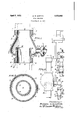
- Fig. 1 is a' vertical central sectional View of my improved flow detector
- Fig. 2 is a transverse section on line 22, Fig. 1
- Fig. 3 is a diagrammatic view illustrating a portion of i a sprinkler systemembodying my improved flow detectors. 7
- 1 represents my improved flow detector comprising acasing which is preferably made of cast metal having an outer wall 3 of conical formation terminating at its apex with a collar 6 forming a pipe connection.
- the collar 6 is shown as having a screwthread 7 formed upon its outerv surface for the attachment of a pipe union 11.
- An inlet opening 9 isthus formed through the collar 6.
- a flange l6 isformed by the inner end of the pipelO and projects into the interior of the casingand terminates in spaced relation with the inlet opening 9.
- the outer wall 3 of the casing together with g the bottom wallf8 and the flange 16' form at pocket 17 which is open toward the inlet opening.
- Said pocket 17 isof annular formation and is adapted to receive the flow of water from :a defective shut off valve in the system whenthe water slowly drips down the n pipe connected, with the inlet opening 9.
- the conical outer wall 3 of the casing is gradually'inclinedoutwardly from the inlet opening 9 to the enlarged portion of the casing forming thepocket 17 so that the water will adhereto' the inner surface of the inclined wall of'the casing and enterthe pocket 17 instead of dripping into the outlet opening 12 surrounded by the upstanding flange 16.
- the casing 1 is provided with an enlarged boss 18 having a threaded aperture 19 formed therein for the attachment of a draw oil valve 20. Said aperture 19 is located adjacent to the bottom wall 8 of the pocket 17 formed in the casing so that water which has accumulated in the pocket may be drawn off through the valve 20.
- Fig. 3 illustrates a sprinkler system embodying an alarm valve 22 connected in "the riser 23 of the system, which pipe 23 supplies water through pipes 24 and 25 to the sprinkler heads 26 arranged at various places throughout the system.
- An alarm device 27 is connected with the alarm valve 22, which device operates when the valve 22 is open and water is flowing through the system.
- the alarm valve 22 is connected by a pipe 28 with a shut off valve 30 adapted for draining the system.
- a pipe 31 connects the shut off valve 80 with my improved flow detector 32, which in turn is connected with a drain pipe 33.
- the shut off valve 30 is open for draining, or testing the system, the water will flow through the flow detector 32 into the drain pipe 33.
- the shut oh. valve 30 is closed, and a leak occurs in the valve the water will flow down the pipe 31 and along the inner surface of the conical wall of the flow detector and accumulate in the pocket 17 of the latter, from which it may be drawn ofi throughthe draw ofi valve 20.
- Upon making an inspection of the system when water is found to have accumulated in the pocket 17 of the flow dectector, a continuous flow through the draw off valve will indicate that the shut off valve is leaking.
- Fig. 3 also shows a flow detector 35 connected with the shut off valve 36 connected with the pipe 24 of the system.
- the flow detector 35 is connected with a drain pipe 37, and operates in the manner above described.
- the flow detectors may be located at various points throughout the system and may be used in either a vertical or horizontal position, thus providing a convenient and satisfactory method of detecting the presence of leaks in the system.
- My improved flow detector is substantially constructed so that it may be installed without the possibility of injury, will not become defective through continuous operation, and may be manufactured at a very low cost.
- My improved device also provides means for readily inspecting the shut off valves to ascertain if there are any leaks which would cause a continuous flow of water.
- My device is simple in operation as it provides a means for inspecting the condition of the valves by simply opening a draw off valve. Upon the opening of which draw off valve, if water is found to have accumulated in the flow detector, it will indicate that the shut ofi' valve is defected.
- a flow detector comprising a hollow conical body portion of truncated formation, a cylindrical inlet connection located above the body portion, a connecting portion between the lower end of the inlet connection and the body (portion having a gradually outwardly curve inner surface extending from the innor cylindrical surface of the inlet connection to the inner conical surface of the body portion whereby water dripping down the surface of the inlet connection will follow the outwardly diverging surface of the conical body portion, an outlet connection arranged in vertical axial alignment with the inlet connection, an inwardly curved bowl shaped portion connected with the lower end of the conical body portion forming an annular receptacle surrounding the outlet connection, said bowl shaped portion having a drain aperture formed therein below the top of the outlet connection. and a valve arranged for opening and closing the drain aperture.
Description
April 1932- w. B. GRIFFITH I 1,852,999
v FLOW DETECTOR Filed March 12, 1950 I Inventor.- William 15'. 7'/fi'70 By Jt-torr zey Patented Apr. 5, 1 932.
COB-YORATIOLL. JERSEY PATENT? OFFICE.
' WILLIAM '.B.'GRIFFITH', F AUDUBON} NEW JERSEY, ASSIGNOR TO STARSPBINKLER' OFI PHILADELPHIA, PENNSYLVANIA, A CORPORATION OFI NEW FLOW :nn'rnc'ron My invention relates I to a flow detector adaptedfonuse insystems requiring piping and valves for shutting off they-flow of water or liquid throughthe pipes. My invention provides a means by which the flow of water from a leaky valve maybe detected without ments are that some form of leak or flow detector'be employed by which a leaky valve may be detected, thus preventing the possibility of a continuous flow of water through a defective valve, which would empty the system or impair its efficient operation.
- further object is to provide the casing with.
I-Ieretofore the-practice has beento employ-- a device having a glass tube, or a glass window, secured in a casing, through which the flow ofwater from, a defective valve may be determined by observation. The obj eotion to this form of device is that the glass tubes or windows become stained, making it impossible to determine whether or not there is any water flowing through the device."
The object-of my invention is to provide a casing havingpipe connections thereon, which may be installed as a permanent part of a sprinkler system; a further object is to provide a casing preferably of cast metal, without any parts which are breakable so that the device may be installed without injury, due to the use of wrenches during installation; a further object of my invention is to provide a casing having an enlarged portion forming a pocket for the accumulation' of water which may flow through the pipes from a defective valve; and a still an aperture for the attachment of a shut off valve through which the water may be drawn from the pocket of the casing, and through.
which the water will continue to flow from a defective valve. These together with various novel features of construction and arrangement of the parts, which will be more fully hereinafter described and claimed,.constitute my invention. I
Referring to the accompanying drawings, Fig. 1 is a' vertical central sectional View of my improved flow detector; Fig. 2 is a transverse section on line 22, Fig. 1; and Fig. 3 is a diagrammatic view illustrating a portion of i a sprinkler systemembodying my improved flow detectors. 7
In'theaccompanying drawings in which like reference characters refer to like parts, 1 represents my improved flow detector comprising acasing which is preferably made of cast metal having an outer wall 3 of conical formation terminating at its apex with a collar 6 forming a pipe connection. The collar 6 is shown as having a screwthread 7 formed upon its outerv surface for the attachment of a pipe union 11. An inlet opening 9 isthus formed through the collar 6.
The enlarged portion of the conical wall 3 of the casing. is joined with an inwardly curved bottom wall- 8 which is integrally formed upon the outer cylindricalsurface l of an outletfpipe 1O which'forms an outlet opening12.' A collar 13 isformed upon the outer end of thepipe 10 and is provided with a screw thread 14; for the attachment-0f a 1111101115. Any-other form ofpipe connection maybe-used.
A flange l6 isformed by the inner end of the pipelO and projects into the interior of the casingand terminates in spaced relation with the inlet opening 9. U I
The outer wall 3 of the casing together with g the bottom wallf8 and the flange 16' form at pocket 17 which is open toward the inlet opening. 9. Said pocket 17 isof annular formation and is adapted to receive the flow of water from :a defective shut off valve in the system whenthe water slowly drips down the n pipe connected, with the inlet opening 9.
, The conical outer wall 3 of the casingis gradually'inclinedoutwardly from the inlet opening 9 to the enlarged portion of the casing forming thepocket 17 so that the water will adhereto' the inner surface of the inclined wall of'the casing and enterthe pocket 17 instead of dripping into the outlet opening 12 surrounded by the upstanding flange 16.
The casing 1 is provided with an enlarged boss 18 having a threaded aperture 19 formed therein for the attachment of a draw oil valve 20. Said aperture 19 is located adjacent to the bottom wall 8 of the pocket 17 formed in the casing so that water which has accumulated in the pocket may be drawn off through the valve 20.
Fig. 3 illustrates a sprinkler system embodying an alarm valve 22 connected in "the riser 23 of the system, which pipe 23 supplies water through pipes 24 and 25 to the sprinkler heads 26 arranged at various places throughout the system. An alarm device 27 is connected with the alarm valve 22, which device operates when the valve 22 is open and water is flowing through the system.
The alarm valve 22 is connected by a pipe 28 with a shut off valve 30 adapted for draining the system. A pipe 31 connects the shut off valve 80 with my improved flow detector 32, which in turn is connected with a drain pipe 33. lVhen the shut off valve 30 is open for draining, or testing the system, the water will flow through the flow detector 32 into the drain pipe 33. When the shut oh. valve 30 is closed, and a leak occurs in the valve the water will flow down the pipe 31 and along the inner surface of the conical wall of the flow detector and accumulate in the pocket 17 of the latter, from which it may be drawn ofi throughthe draw ofi valve 20. Upon making an inspection of the system, when water is found to have accumulated in the pocket 17 of the flow dectector, a continuous flow through the draw off valve will indicate that the shut off valve is leaking.
Fig. 3 also shows a flow detector 35 connected with the shut off valve 36 connected with the pipe 24 of the system. The flow detector 35 is connected with a drain pipe 37, and operates in the manner above described.
The flow detectors may be located at various points throughout the system and may be used in either a vertical or horizontal position, thus providing a convenient and satisfactory method of detecting the presence of leaks in the system.
My improved flow detector is substantially constructed so that it may be installed without the possibility of injury, will not become defective through continuous operation, and may be manufactured at a very low cost. My improved device also provides means for readily inspecting the shut off valves to ascertain if there are any leaks which would cause a continuous flow of water. My device is simple in operation as it provides a means for inspecting the condition of the valves by simply opening a draw off valve. Upon the opening of which draw off valve, if water is found to have accumulated in the flow detector, it will indicate that the shut ofi' valve is defected.
Various changes may be made in the construction and the arrangement of the parts without departing from my invention.
I claim A flow detector comprising a hollow conical body portion of truncated formation, a cylindrical inlet connection located above the body portion, a connecting portion between the lower end of the inlet connection and the body (portion having a gradually outwardly curve inner surface extending from the innor cylindrical surface of the inlet connection to the inner conical surface of the body portion whereby water dripping down the surface of the inlet connection will follow the outwardly diverging surface of the conical body portion, an outlet connection arranged in vertical axial alignment with the inlet connection, an inwardly curved bowl shaped portion connected with the lower end of the conical body portion forming an annular receptacle surrounding the outlet connection, said bowl shaped portion having a drain aperture formed therein below the top of the outlet connection. and a valve arranged for opening and closing the drain aperture.
In testimony whereof I afiix my sigiature.
WILLIAM B. GRIF TH.
Publications (1)
| Publication Number | Publication Date |
|---|---|
| US1852999A true US1852999A (en) | 1932-04-05 |
Family
ID=3423643
Family Applications (1)
| Application Number | Title | Priority Date | Filing Date |
|---|---|---|---|
| US1852999D Expired - Lifetime US1852999A (en) | Flow detector |
Country Status (1)
| Country | Link |
|---|---|
| US (1) | US1852999A (en) |
Cited By (3)
| Publication number | Priority date | Publication date | Assignee | Title |
|---|---|---|---|---|
| US4022421A (en) * | 1975-12-01 | 1977-05-10 | Carlin Jack M | Delayed release valve for a fire hydrant |
| US4182376A (en) * | 1977-08-08 | 1980-01-08 | Forsheda Gummifabrik Ab | Device for dispensing a liquid flowing through a substantially vertical tube |
| US20110041416A1 (en) * | 2009-08-21 | 2011-02-24 | Schmidt Matthew L | Rainwater diverter |
-
0
- US US1852999D patent/US1852999A/en not_active Expired - Lifetime
Cited By (4)
| Publication number | Priority date | Publication date | Assignee | Title |
|---|---|---|---|---|
| US4022421A (en) * | 1975-12-01 | 1977-05-10 | Carlin Jack M | Delayed release valve for a fire hydrant |
| US4182376A (en) * | 1977-08-08 | 1980-01-08 | Forsheda Gummifabrik Ab | Device for dispensing a liquid flowing through a substantially vertical tube |
| US20110041416A1 (en) * | 2009-08-21 | 2011-02-24 | Schmidt Matthew L | Rainwater diverter |
| US8528263B2 (en) * | 2009-08-21 | 2013-09-10 | Oatey Co. | Rainwater diverter |
Similar Documents
| Publication | Publication Date | Title |
|---|---|---|
| EP3434833B1 (en) | Simplified method for testing a backflow preventer assembly | |
| US3343560A (en) | Anti-hammer under-fixture valve | |
| US2760596A (en) | Automatic dumping liquid trap | |
| US1852999A (en) | Flow detector | |
| US3081631A (en) | Thermometer well for pipes | |
| US2019421A (en) | Attachment for refrigerating systems | |
| US1831318A (en) | Float operated valve | |
| US1720819A (en) | Test t. | |
| US2607225A (en) | Liquid level gauge | |
| US2892641A (en) | Mounting for fluid meter | |
| US1901797A (en) | Ejector | |
| US1936537A (en) | Air-vacuum valve combined with airrelease valve | |
| US2279513A (en) | Valve | |
| US1944249A (en) | Protective device for hose lines | |
| US2645243A (en) | Relief valve manifold | |
| KR20090060727A (en) | Saddle for detecting a water leakage and drainage valve using the same | |
| US2888038A (en) | Automatic shut-off valve mechanism for tanks and the like | |
| US1179441A (en) | Sight-drain. | |
| US3072140A (en) | Blow-off fitting | |
| CN205599160U (en) | Liquid medium interface separating/distinguishing device | |
| US2270447A (en) | Tank testing device | |
| US960944A (en) | Water-gage. | |
| US3667493A (en) | Float valve for air line lubricators | |
| US1845736A (en) | Leak-detector valve and attaching fitting | |
| US1068280A (en) | Apparatus for measuring flow of liquids in closed conduits. |