US1852954A - Tractor wheel - Google Patents
Tractor wheel Download PDFInfo
- Publication number
- US1852954A US1852954A US474533A US47453330A US1852954A US 1852954 A US1852954 A US 1852954A US 474533 A US474533 A US 474533A US 47453330 A US47453330 A US 47453330A US 1852954 A US1852954 A US 1852954A
- Authority
- US
- United States
- Prior art keywords
- wheel
- tractor
- slots
- disc
- rim
- Prior art date
- Legal status (The legal status is an assumption and is not a legal conclusion. Google has not performed a legal analysis and makes no representation as to the accuracy of the status listed.)
- Expired - Lifetime
Links
Images
Classifications
-
- B—PERFORMING OPERATIONS; TRANSPORTING
- B60—VEHICLES IN GENERAL
- B60B—VEHICLE WHEELS; CASTORS; AXLES FOR WHEELS OR CASTORS; INCREASING WHEEL ADHESION
- B60B15/00—Wheels or wheel attachments designed for increasing traction
- B60B15/02—Wheels with spade lugs
-
- B—PERFORMING OPERATIONS; TRANSPORTING
- B60—VEHICLES IN GENERAL
- B60B—VEHICLE WHEELS; CASTORS; AXLES FOR WHEELS OR CASTORS; INCREASING WHEEL ADHESION
- B60B15/00—Wheels or wheel attachments designed for increasing traction
- B60B15/02—Wheels with spade lugs
- B60B15/023—Wheels with spade lugs being of the broad form type
- B60B15/025—Wheels with spade lugs being of the broad form type with non-cylindrical shape
-
- B—PERFORMING OPERATIONS; TRANSPORTING
- B60—VEHICLES IN GENERAL
- B60Y—INDEXING SCHEME RELATING TO ASPECTS CROSS-CUTTING VEHICLE TECHNOLOGY
- B60Y2200/00—Type of vehicle
- B60Y2200/20—Off-Road Vehicles
- B60Y2200/22—Agricultural vehicles
- B60Y2200/221—Tractors
Definitions
- This invention relates to tractor wheels in general and particularly .to the kind adapted to be useful in connection with work in sticky or wet earth, and especially in field soft or wet, the ordinary type of tractor the tendency to packthe ground especially between what is known as traction flights, which packing makes the wheels practically useless after a period of working time.
- the primary object of my invention is to provide a tractor wheel which will eliminate the disadvantages found in present,
- Another object of 'myinvention is to so automatically cleaning the traction surface of the latter.
- Fig. .1 is a side elevation of;my tractor wheel illustrating the outer wheel side;
- Fig. 2 is an end elevation thereof
- Fig. 3 is a cross sectional view taken on line 3-3 of Fig. 1; and 1 I Fig. 4 is an enlarged perspective detail view of a portion of my wheel.
- numeral 10 denotes a hub to'whichisattached at one of its ends a disc 11,while at the other end another disc 12'is secured.
- Disc 12 is clearly seen from F ig. land is provided with a plurality or yradi'al' slots-13 extending tom practically the outer peripheryof the disc towards but'not quite to'the hub portion of I the disc.
- traction means 16' in the form'of fii'ghts, the form of which; is essentially Zeshaped.
- The' flights are','disposed 7 withtheir longest portions adjacent, to one side of slots 14 provided in the rim, while the ends of the flights are extended peripherally alongside the edgesiof the two wheel discs as clearly seen at" 17 in the drawings. These extensions 17 "are substantially in the plane. of the wheel discs. t
- left and righthand tractor wheels are employed and that their flights and slots are disposed in diagonally outward and forward directions.
- a hub In attraction wheel, a hub, a pair of spaced side disks, one disc being secured to the inner end of the hub and the other disc being securedto the outer end of the hub, said last mentioned disc being provided with radial slots, a rim connecting the peripheries of said disks, and provided with diagonally forwardly extending transverse slots corresponding in number to the number of the first mentioned slots, chutes corresponding in direction with the rim slotsoand connecting the rim slots with the disc slots for the purpose of extruding dirt forwardly and laterally, and a plurality of traction flights at the outer periphery of the rim adjacent the rim slots, each flight having circumferentially extending end portions, the number of flights equalling the number of said rim slots.
Description
April 5, 1932. CLOUD 1,852,954
TRACTOR WHEEL Filed Aug. 11, 1930 Z0517 Cg qgg ATTORNEY 1 construct "my tractor wheel that whatever soft earth or dirt contacts with the wheel, f moved sidewise and out of the wheel, thereby .work. -Where the ground is sandy,
wheels have Patented Apr. 5,- 1932 i Loni. moon, or nusnv rnninnmna:
TRACTOR? WHEEL Application filed Augustll, 1930. Seria1tNo..474,533/' This invention; relates to tractor wheels in general and particularly .to the kind adapted to be useful in connection with work in sticky or wet earth, and especially in field soft or wet, the ordinary type of tractor the tendency to packthe ground especially between what is known as traction flights, which packing makes the wheels practically useless after a period of working time.
The primary object of my invention, therefore, is to provide a tractor wheel which will eliminate the disadvantages found in present,
day tractor wheels and particularly prevent packing.
Another object of 'myinvention is to so automatically cleaning the traction surface of the latter. I j
Other objects and advantages of the invention will be hereinafter specifically pointed out or will become apparent as the specificationproceeds. V
With the above ind cated ob ects in view, the inventlon resides in certain novel constructions and combinations and arrangement of parts, clearlydescribed in the following specification and fully illustrated 1n the accompanying drawings, which latter show embodiments of the invention as at Y present preferred. 7 I
In the drawings:
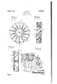
Fig. .1 is a side elevation of;my tractor wheel illustrating the outer wheel side;
Fig. 2 is an end elevation thereof;
Fig. 3 is a cross sectional view taken on line 3-3 of Fig. 1; and 1 I Fig. 4 is an enlarged perspective detail view of a portion of my wheel.
Similar reference characters refer to simi-' lar parts throughoutthe several views of the drawings.
Referring now morefin detail to the embodiment of my tractor wheel, numeral 10 denotes a hub to'whichisattached at one of its ends a disc 11,while at the other end another disc 12'is secured. Disc 12 is clearly seen from F ig. land is provided with a plurality or yradi'al' slots-13 extending tom practically the outer peripheryof the disc towards but'not quite to'the hub portion of I the disc.
' Connecting the 'twoside discs with each 66 other there is provided a peripheral rim equipped'with diagonally disposed transverse slots indicated'at; 14. These slots 14 communicate with slots 13 of the outer wheel disc by means of pockets or chutes indicated T at 15, the number, of slots in the oute'r'disc 7 corresponding with the, number of slots provided in the rim and the mentioned chutes extending inthe direction of the rim 'slots '14., so that the dirt will be extruded forwardly and laterally. I I v I Extending from the rim outwards, there,
will'f'be' observed traction means 16' in the form'of fii'ghts, the form of which; is essentially Zeshaped. .The' flights are','disposed 7 withtheir longest portions adjacent, to one side of slots 14 provided in the rim, while the ends of the flights are extended peripherally alongside the edgesiof the two wheel discs as clearly seen at" 17 in the drawings. These extensions 17 "are substantially in the plane. of the wheel discs. t
0peratz'0n. 'lhe function of-my tractor wheel is vastly ,diiferent from that of tractor pressed againstthe rim of the wheel,fbut forced into slots 14 and thereby through chutes 15 outwards and on to the side of the wheel. In this manner a tractor equipped with my tractor wheelsmay move continuously without losing traction and with a mini-. mum or practically no accumulation of dirt upon the surface of the tractor wheel. It is obvious that in providing a tractor with my wheels, the non-slotted disc portion of the wheel faces the tractor itself while the slotted disc is facing outwards. Such application prevents pilingup of .dirt' under the tractor or against the tractor machinery which would be inevitable if the discharge of chutes 15 were directed inwards.
Attention is called to the arrangement of slots 14 and flights 16 relative tothe wheel it tions of flights 16 and their adjacent slots 14 wheels used heretofore in that'the dirt is'not are directed outwards so that the earth or mud, engaged by the flights may pass unrestrictedly through the chutes upwards and be discharged in forward direction. If the arrangement of flights 16 and slots 14 would be reversed the mud or earth would be forced directly against the rear walls of the chutes and would have to travel rearwards before discharging. This would cause binding and would require greater force for discharging the earth, resulting in clogging of chutes.
It is essential, therefore that left and righthand tractor wheels are employed and that their flights and slots are disposed in diagonally outward and forward directions.
The hereinabove described construction ad- .mits of considerable modification Without departing from the invention; therefore, it is my wish not to be limited to the precisearrangements shown and described, which are oasaforesaid, by way of illustration merely.
In other words, the scope of protection contemplated is to be taken solely from the appended claim, interpreted as broadly as is consistent with the prior art.
What is claimed is:
In attraction wheel, a hub, a pair of spaced side disks, one disc being secured to the inner end of the hub and the other disc being securedto the outer end of the hub, said last mentioned disc being provided with radial slots, a rim connecting the peripheries of said disks, and provided with diagonally forwardly extending transverse slots corresponding in number to the number of the first mentioned slots, chutes corresponding in direction with the rim slotsoand connecting the rim slots with the disc slots for the purpose of extruding dirt forwardly and laterally, and a plurality of traction flights at the outer periphery of the rim adjacent the rim slots, each flight having circumferentially extending end portions, the number of flights equalling the number of said rim slots.
. In testimony whereof I hereby afiix my signature.
LOEL CLOUD.
Priority Applications (1)
| Application Number | Priority Date | Filing Date | Title |
|---|---|---|---|
| US474533A US1852954A (en) | 1930-08-11 | 1930-08-11 | Tractor wheel |
Applications Claiming Priority (1)
| Application Number | Priority Date | Filing Date | Title |
|---|---|---|---|
| US474533A US1852954A (en) | 1930-08-11 | 1930-08-11 | Tractor wheel |
Publications (1)
| Publication Number | Publication Date |
|---|---|
| US1852954A true US1852954A (en) | 1932-04-05 |
Family
ID=23883924
Family Applications (1)
| Application Number | Title | Priority Date | Filing Date |
|---|---|---|---|
| US474533A Expired - Lifetime US1852954A (en) | 1930-08-11 | 1930-08-11 | Tractor wheel |
Country Status (1)
| Country | Link |
|---|---|
| US (1) | US1852954A (en) |
Cited By (2)
| Publication number | Priority date | Publication date | Assignee | Title |
|---|---|---|---|---|
| US6065818A (en) * | 1998-07-02 | 2000-05-23 | Caterpillar, Inc. | Rubber track belt with improved traction and durability |
| US20220072900A1 (en) * | 2020-09-04 | 2022-03-10 | KSi Conveyor, Inc. | Traction Sleeve Roller |
-
1930
- 1930-08-11 US US474533A patent/US1852954A/en not_active Expired - Lifetime
Cited By (2)
| Publication number | Priority date | Publication date | Assignee | Title |
|---|---|---|---|---|
| US6065818A (en) * | 1998-07-02 | 2000-05-23 | Caterpillar, Inc. | Rubber track belt with improved traction and durability |
| US20220072900A1 (en) * | 2020-09-04 | 2022-03-10 | KSi Conveyor, Inc. | Traction Sleeve Roller |
Similar Documents
| Publication | Publication Date | Title |
|---|---|---|
| US1389285A (en) | Vehicle-wheel | |
| US1852954A (en) | Tractor wheel | |
| US2197662A (en) | Tire of the type adapted to be used on automobiles and various vehicles | |
| US2586051A (en) | Front tractor tire | |
| US880122A (en) | Wheel. | |
| US3017933A (en) | Digging wheel for sugar beet harvesters | |
| US1360451A (en) | Traction-wheel | |
| US1342493A (en) | Tractor-wheel | |
| US1486634A (en) | Antislipping device for vehicle werels | |
| US2023304A (en) | Tractor wheel | |
| US1420871A (en) | Traction wheel | |
| US980981A (en) | Traction-wheel. | |
| US1872079A (en) | Traction wheel | |
| US935104A (en) | Driving-wheel for sleighs. | |
| US783034A (en) | Traction-wheel. | |
| US1098757A (en) | Mulching and packing implement. | |
| US1416237A (en) | Traction device | |
| SU893588A1 (en) | Wheel spreader | |
| US1187577A (en) | Traction-wheel. | |
| US1698451A (en) | Packing and mulching implement | |
| US1333055A (en) | Traction-wheel | |
| US1297493A (en) | Traction-wheel. | |
| US1104934A (en) | Traction-wheel. | |
| US1355505A (en) | Wheel consteuctioit | |
| US1451991A (en) | Drive-wheel rim |