US1852835A - Generator overload stop - Google Patents
Generator overload stop Download PDFInfo
- Publication number
- US1852835A US1852835A US19117A US1911725A US1852835A US 1852835 A US1852835 A US 1852835A US 19117 A US19117 A US 19117A US 1911725 A US1911725 A US 1911725A US 1852835 A US1852835 A US 1852835A
- Authority
- US
- United States
- Prior art keywords
- engine
- generator
- load
- ignition
- speed
- Prior art date
- Legal status (The legal status is an assumption and is not a legal conclusion. Google has not performed a legal analysis and makes no representation as to the accuracy of the status listed.)
- Expired - Lifetime
Links
Images

Definitions
- This invention relates to generator overload stops for gas engine operated generators and has for its object to provide means for automatically stopping the operation of the 5 generator when the load becomes excessive.
- the invention is particularly designed for use with automatic self-starting and stopping internal combustion engine driven farm lighting and consists in providing a generator having a voltage control characteristic under which the speed of the generator increases with the load and a cut-out sensitive to the speed, the object of the 1nvention being to stop the engine upon the occurrence of an overload.
- An object of the invention is to stop the operation of the generating unit when overloaded and compel attention and removal 0 the overload condition by requiring the cutout to be reset before operation is resumed.
- Another object of the invention is to provide an ignition controlling switch actuated by a centrifugally operated means whereby the switch will render the ignition circult inoperative to stop the engine when the load becomes excessive.
- Another object of the invention is to perfect details of construction of such an ignltion cut-out switch and the centrifugal operating means therefor.
- Fig. l- is a diagram of the circuits of a gas-engine-operated generating system with which the generator overload stop of this invention is suitable for use and showing the ignition circuit controlled by the cut-out;
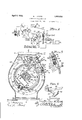
- Fig. 2 is a sectional elevation of the gas engine through the fiy-wheel of the gas engine, showing the cut-out switch and the centrifugal operating means therefor in their assembled relation; 7 ,Fig. 3 is a sectional view on the plane of line 33 of Fig. 2 and showing by the line 22 the sectional plane-of Fig. 2;
- Fig. 4 is an enlarged sectional view on the line 44.- of Fig. 2 showing the relation of tliie cut-out switch and its centrifugal opera or;
- Fig. 5 is a detailed sectional View of the cut-out switch in its closed position for stopping vthe engine, its other position being shown in dotted lines, and
- Fig. 6 is a perspective view of the springpressed operating means for the cut-out switch.
- 10 indicates a generator driven by an internal combustion engine 9, the throttle valve 11 of which is controlled by a solenoid having windings connected with the generator windings, as will be described.
- the generator as shown, is of the shunt type and supplies the mains 12 containing lamps 13 or other translating devices.
- the shunt field winding 14: of the generator is opposed by a bucking series field winding 15, which becomes stronger as the load on the mains increases and thereby opposes a greater influence to the shunt field to weaken the field strength.
- a series coil 16 also in the load circuit and strengthened by the increasing load, opposes to a greater extent the influence of a shunt or voltage coil 17 to effect a further opening movement of the throttle valve of the engine to increase the speed of the engine.
- the solenoid is so constructed that the voltage coil .17 of many turns of fine wire connected in parallel with the shunt field 14 and the current or series coil 16 of few turns of large wire in the load circuittogether act upon the core 21 but in opposition s' to each other.
- the solenoid core is pivotally connected to the shorter arm of abell-crank lever 23, the other arm of which is connettedby a link 27 with the throttle 11 so that in the extreme upper position of the core, as when the generator is not operating and the coils are therefore not energized, the throttle is held in an open position.
- the core is held in this position by a compression coil spring 25 which afi'ords a yielding resistance to the operation of the solenoid core.
- the series coil 16 opposes the voltage coil 17 only slightly or not at all, and the core will be drawn to a lower position against the action of spring and will move the throttle to a position partially closing the mtake manifold of the engine, so that the engine operates at a minimum speed under which the generator develops the line voltage.
- the generator field is weakened by the bucking series field 15, as above mentioned, and the influence of the bucking current coil or series coil 16 becomes greater, tending to neutralize the influence of the voltage coil 17 and permit the spring 25 to hit the core and move the throttle toward its open position, thus increasing the supply of fuel to the engine to increase its speed corresponding with the increase in the load.
- the weakening of the generator eld by the bucking coil 15 serves to facilitate the increasing of the speed of the engine caused at the'same time by the bucking influence of the series coil 16 of the solenoid opening the throttle, and this bucking field winding exaggerates the speed variation characteristic of the generator for constant voltage conditions so that the desired object is accomplished of materially reducing fuel consumption to correspond with a reduction of load.
- a resistance is connected in series with the shunt field winding 14 of the generator and wires 31 and 32 connect the ends of this resistance with switch contacts 33 and 34, respectively, of a resistance short-circuiting switch operated by a solenoid which is connected across the terminals of the generator preferably with a resistance 51 in series therewith.
- the field regulating resistance short circuit is controlled by a switch independent of the throttle-controlling solenoid but sensitive to the variation in voltage developed by the generator. Being independent it is not affected by the spring adjustment of the solenoid core.
- the gas engine 9 may be of the air cooled type having a blower fan incorporated with its fly wheel 61 to draw air through passageways around the cylinders and the ignition may depend upon a magneto also incorporated in the fly wheel as shown, though these features are not essential to the invention.
- the magneto comprises a stationary coil 62 having arc-shaped pole pieces 63 fixed on studs 64 projecting from a removable cover plate 65 for the crank-case of the engine, which cover plate also carries the bearing 66 for the crank shaft 67.
- the arcshaped permanent magnets 68 are carried by a ring 69 of non-magnetic material, which is clamped on the fly wheel by screws 70, and pole pieces 71, also clamped on the ring 69 by screws 72, travel around and close to the pole-pieces 63 of the stationary magnet 62, there being primary and secondary lead wires 7 3 and 7 4 respectively, extending from the coil 62 to the usual breaker and distrib uter shown in diagram Fig. 1.
- This member as best seen in Fig. 5, constitutes a lever fulcrumed at 7 6 between ears of a metal block 77, which is secured to the inner side of the casing 78 of the engine by screws 79, said lever being of angular shape with its end extending through an opening in the casing with a knob 80 outside the cas ing, which, indicates; the position bf the switch and'serves as the means for resetting the switch after .it has been, automatically operated, as will be explained.
- the switch lever 75 is held by spring pressure in. either its inner position or its outer position by a bow sprin 81 fitting at one end in a notch in the end block 77 and at the insulated from the bloc'k7 7.
- the contact consists of a rivet passing through areduced portion of the block 7 7 primary lead 7 3 of the magneto leading to the with insulating washers to protect .it from electrical connection with said block and with a connecting plate 84 connected bya wire 85- with'the-circuit breaker, said wire 85 and the same-binding post of the circuit breaker for convenience. It will be seen that, inasmuch. as the lever is grounded on the casing through the block 77, its contact with the contact 83 serves to ground the ignition lead and thereby render the magneto inefiective .for producing ignition in the well known manner.
- the normalposition for the cut-out switch lever 75 isits inner position, shown by dotted lines in Fig. '5, but a centrifugally operated means is provided for engaging it and throwing it to-its outer position to'ground the magneto automatically when a predetermined speed is attained, that is when the generator is overloaded.
- Such operating means may consist of an arm 86 pivotally mounted on the side ring of the blower fan 60 and held with spring pressure in a normalinner position where its laterally extending rounded proj ection 87 clears the angular bend or elbow of the cut-out lever 75,'the weight of said. arm, however. being suflicient to cause it to swing outwardly against the. pressure of its spring to'engage the lever 75 and move it to its outer position to ground the magneto when an ex cessive speedis reached.
- the arm 86 has a side lug 88 bent up at right angles to it ina vertical'plane and in an opening of said lug is-a loose bushing 89. slightly thicker than the lug, as seen in Fig. 4, to afl'ord a free bearing for the arm when said bushing is clamped to the side ring of the blower 60 by means -of a bolt'90 with washer 9 1.
- a leaf spring-92' is riveted to the arm near its lug and bears against one of the blades of the blower fan, asseen' in Fig. 2, the inward movement of the arm being limited by its engagement with another blade of the blower fan and the outer movement by a stop lug 93 bn its end engaging the spring.
- the ignition system is effective for operating the engine, but upon a failure of the voltage regulator to properly control the speed of the engine so that the engine races or exceeds its predetermined speed, the centrifugal force acting upon the arm moves it outwardly until its lateral rounded projection 87 strikesthe lever 75 and throws lit to its outer position, where it is held by the -spring 81 in engagement with the contact 83 toground the magneto and thereby render the ignition ineffective so that the engine stops.
- the system with which the ignition cut-out of this invention is used is ofothe demand "starter type, the continuance of the load on the mainsis incapable of again starting the unit in operation until the at-- tendant resetstlie cut-out switch lever 75 to remove the ground connection from the magneto, thus insuring that proper'inspection will be made and the overload removed or defect remedied to prevent a recurrence of the "excessive speed beforethe system is again started.
- the invention has been described i connection with a particular gas-engine-operated lighting and power unit wherein magneto ignition is relied on, it is not limited to such use but may be used in any system wherej in it is desired to stop the operation of a gas engine or the like whether dependin on magneto ignition or battery ignition, it eing understood that the usual modification is implied for battery ignition control whereby the battery circuit s opened to be rendered inoperative instead of being-grounded by the operation ofthe cut-out switch lever.
- a generator overload cut-out comprising a ga's-engine-driven generator and its ignition circuit a voltage regulator increasing the speed of the generator with an increase of the load, a centrifugally operated arm driven by the engine, an ignition cut-out switch in the path of the arm to be engaged thereby in the position of the arm asopen and a closed position and being moved 'from one position to the other by the engagement of the arm therewith, and a spring u'rg ing the cut-out switch to either of its positions, saidcut-out switch serving to control the ignition circuit.
- a generator overload cut-out comprising a gas-engine-driven generator having its speed v'arymg with the load, an arm pivotally mounted on the fly wheel of the engine,
- said switch comthe occurrence of an overload on the mains or prising a pivotally mounted switch lever within the engine casing and projecting through an opening thereof and adapted to be engaged by the arm and having an inner and an outer position, a spring for holding the lever in either of its positions, and -a contact engaged by the lever when it is moved to its outer position for rendering the ignition circuit of the engine ineffective.
- a generator overload cut-out comprising a gas-engine-driven generator having its speed varying with the load, an arm pivotally mounted on the fly wheel of the engine, a spring for holding the arm in an inner position but yielding to permit the arm to swing outwardly under the action of centrifugal force, a block mounted within the engine casing, a lever pivotally mounted thereon with its end passing through an opening in the casing and having an inner and an outer position, the inner position being in the path of the arm when it is moved outwardly by centrifugal force, a bow spring connecting the lever and the block, acontact on the block engaged by the lever, and an ignition magneto for the engine having its primary winding connected with the contact whereby said magneto is grounded by the lever in its outer position.
- Means for preventing subnormal voltage operation of gas-engine-driven generator units of the demand-responsive type by stop ping the unit upon the occurrence of an overload comprising, in combination with such unit, engine throttle controlling means sensitive to the load increasing the speed as the load increases, and a centrifugal ignition cutout responsive to such increase of speed.
- Means for stopping a generator upon the occurrence of an overload on the mains comprising a gas-engine-driven generator, engine controlling means for increasing the speed thereof when the load increases, and disabling means for the gas engine dependent on the speed.
Description
April 5, 1932. A. F. BROTZ GENERATOR OVERLOAD STOP 1925 2 SheetsSheet Filed March 28 Etc; .1
M l o m w m 5 R 1 0 am V 50 55/ ATTRNEY A. F. BROTZ 1,852,835
GENERATOR OVERLOAD STOP April 5, 1932.
Filed March 28, 1925 2 Sheets-Sheet 2 2 FIG.
and power plants Patented Apr. 5, 1932 UNITED STATES PATENT OFFICE ANTON FRANK BROTZ, OF KOHLER, WISCONSIN, ASSIGNOR TO KOHLER COMPANY, OF KOHLER, WISCONSIN, A CORPORATION OF WISCONSIN GENERATOR OVERLOAD STOP Application filed March 28, 1925. Serial No. 19,117.
This invention relates to generator overload stops for gas engine operated generators and has for its object to provide means for automatically stopping the operation of the 5 generator when the load becomes excessive.
Although not confined thereto, the invention is particularly designed for use with automatic self-starting and stopping internal combustion engine driven farm lighting and consists in providing a generator having a voltage control characteristic under which the speed of the generator increases with the load and a cut-out sensitive to the speed, the object of the 1nvention being to stop the engine upon the occurrence of an overload.
An object of the invention is to stop the operation of the generating unit when overloaded and compel attention and removal 0 the overload condition by requiring the cutout to be reset before operation is resumed.
Another object of the invention is to provide an ignition controlling switch actuated by a centrifugally operated means whereby the switch will render the ignition circult inoperative to stop the engine when the load becomes excessive.
Another obiect of the invention is to perfect details of construction of such an ignltion cut-out switch and the centrifugal operating means therefor.
.With the above and other objects in v1ew the invention consists in the generator overload stop as herein claimed and all equivalents.
Referring to the accompanying drawlngs in which like characters of reference indicate the same parts in different views,
Fig. l-is a diagram of the circuits of a gas-engine-operated generating system with which the generator overload stop of this invention is suitable for use and showing the ignition circuit controlled by the cut-out;
Fig. 2 is a sectional elevation of the gas engine through the fiy-wheel of the gas engine, showing the cut-out switch and the centrifugal operating means therefor in their assembled relation; 7 ,Fig. 3 is a sectional view on the plane of line 33 of Fig. 2 and showing by the line 22 the sectional plane-of Fig. 2;
Fig. 4 is an enlarged sectional view on the line 44.- of Fig. 2 showing the relation of tliie cut-out switch and its centrifugal opera or;
Fig. 5 is a detailed sectional View of the cut-out switch in its closed position for stopping vthe engine, its other position being shown in dotted lines, and
Fig. 6 is a perspective view of the springpressed operating means for the cut-out switch.
In these drawings, 10 indicates a generator driven by an internal combustion engine 9, the throttle valve 11 of which is controlled by a solenoid having windings connected with the generator windings, as will be described.
f The generator, as shown, is of the shunt type and supplies the mains 12 containing lamps 13 or other translating devices. The shunt field winding 14: of the generator is opposed by a bucking series field winding 15, which becomes stronger as the load on the mains increases and thereby opposes a greater influence to the shunt field to weaken the field strength. At the same time a series coil 16, also in the load circuit and strengthened by the increasing load, opposes to a greater extent the influence of a shunt or voltage coil 17 to effect a further opening movement of the throttle valve of the engine to increase the speed of the engine.
The solenoid is so constructed that the voltage coil .17 of many turns of fine wire connected in parallel with the shunt field 14 and the current or series coil 16 of few turns of large wire in the load circuittogether act upon the core 21 but in opposition s' to each other. The solenoid core is pivotally connected to the shorter arm of abell-crank lever 23, the other arm of which is connettedby a link 27 with the throttle 11 so that in the extreme upper position of the core, as when the generator is not operating and the coils are therefore not energized, the throttle is held in an open position. The core is held in this position by a compression coil spring 25 which afi'ords a yielding resistance to the operation of the solenoid core.
When the generator is started with a minimum load or no load on the service mains, the series coil 16 opposes the voltage coil 17 only slightly or not at all, and the core will be drawn to a lower position against the action of spring and will move the throttle to a position partially closing the mtake manifold of the engine, so that the engine operates at a minimum speed under which the generator develops the line voltage. As the load increases the generator field is weakened by the bucking series field 15, as above mentioned, and the influence of the bucking current coil or series coil 16 becomes greater, tending to neutralize the influence of the voltage coil 17 and permit the spring 25 to hit the core and move the throttle toward its open position, thus increasing the supply of fuel to the engine to increase its speed corresponding with the increase in the load.
The proportioning of the field wlndin of the generator and of the coils of the solenoid and of the throttle and its operating means,
is made to compensate for a change in load by causing a change in speed without a material change in voltage developed by the enerator. The weakening of the generator eld by the bucking coil 15 serves to facilitate the increasing of the speed of the engine caused at the'same time by the bucking influence of the series coil 16 of the solenoid opening the throttle, and this bucking field winding exaggerates the speed variation characteristic of the generator for constant voltage conditions so that the desired object is accomplished of materially reducing fuel consumption to correspond with a reduction of load.
For increased independent regulation a resistance is connected in series with the shunt field winding 14 of the generator and wires 31 and 32 connect the ends of this resistance with switch contacts 33 and 34, respectively, of a resistance short-circuiting switch operated by a solenoid which is connected across the terminals of the generator preferably with a resistance 51 in series therewith. Thus the field regulating resistance short circuit is controlled by a switch independent of the throttle-controlling solenoid but sensitive to the variation in voltage developed by the generator. Being independent it is not affected by the spring adjustment of the solenoid core.
By this arrangement the momentary rise in voltage when the load is suddenly reduced from full load to minimum load is prevented, the sudden weakening of the bucking current coil 16 accompanied by a slight strengthening of the voltage coil 17 being sufficient to cause the core 21 to move to the position for closing the throttle. At the same time the voltage coil 50, because of its momentary rise in voltage, opens the contacts 33 and 34, thus break ing the short circuit around the regulating resistance 30 including this resistance in the shunt field winding to weaken the fields and check the rise in voltage. Such tendency to abnormal voltage is only momentary and as soon as the speed of the generator has reduced to correspond with the new throttle position, the normal conditions are restored the throttle position being determined by the differential solenoid 16-17 and the field resistance short-circuiting switch being permitted to close by the voltage coil 50.
As so far described the system is like that covered by my application for voltage regulators, Serial No. 656,334, and is only given in detail herein in order to exemplify the class of generating units chosen for use with a speed-sensitive ignition cut-out to constitute the generator overload cut-out because the characteristic is present of an increasing speed with an increasing load.
It has been found in practice that with all farm lighting plant generating systems in the hands of unskilled operators there is a tendency to increase the load beyond the rated capacity attended by the danger of possible damage and to prevent this practice the present invention provides for automatically stopping the engine when the load becomes excessive.
The gas engine 9 may be of the air cooled type having a blower fan incorporated with its fly wheel 61 to draw air through passageways around the cylinders and the ignition may depend upon a magneto also incorporated in the fly wheel as shown, though these features are not essential to the invention.
As shown, the magneto comprises a stationary coil 62 having arc-shaped pole pieces 63 fixed on studs 64 projecting from a removable cover plate 65 for the crank-case of the engine, which cover plate also carries the bearing 66 for the crank shaft 67. The arcshaped permanent magnets 68 are carried by a ring 69 of non-magnetic material, which is clamped on the fly wheel by screws 70, and pole pieces 71, also clamped on the ring 69 by screws 72, travel around and close to the pole-pieces 63 of the stationary magnet 62, there being primary and secondary lead wires 7 3 and 7 4 respectively, extending from the coil 62 to the usual breaker and distrib uter shown in diagram Fig. 1.
The ignition cut-out of this invention which is to render the ignition ineffective when the generator is subjected to an excesssive load comprises a cut-out switch member for grounding the primary of the magneto. This member, as best seen in Fig. 5, constitutes a lever fulcrumed at 7 6 between ears of a metal block 77, which is secured to the inner side of the casing 78 of the engine by screws 79, said lever being of angular shape with its end extending through an opening in the casing with a knob 80 outside the cas ing, which, indicates; the position bf the switch and'serves as the means for resetting the switch after .it has been, automatically operated, as will be explained. d i
The switch lever 75 is held by spring pressure in. either its inner position or its outer position by a bow sprin 81 fitting at one end in a notch in the end block 77 and at the insulated from the bloc'k7 7. In the form shown the contact consists of a rivet passing through areduced portion of the block 7 7 primary lead 7 3 of the magneto leading to the with insulating washers to protect .it from electrical connection with said block and with a connecting plate 84 connected bya wire 85- with'the-circuit breaker, said wire 85 and the same-binding post of the circuit breaker for convenience. It will be seen that, inasmuch. as the lever is grounded on the casing through the block 77, its contact with the contact 83 serves to ground the ignition lead and thereby render the magneto inefiective .for producing ignition in the well known manner.
The normalposition for the cut-out switch lever 75 isits inner position, shown by dotted lines in Fig. '5, but a centrifugally operated means is provided for engaging it and throwing it to-its outer position to'ground the magneto automatically when a predetermined speed is attained, that is when the generator is overloaded. 5 Such operating means may consist of an arm 86 pivotally mounted on the side ring of the blower fan 60 and held with spring pressure in a normalinner position where its laterally extending rounded proj ection 87 clears the angular bend or elbow of the cut-out lever 75,'the weight of said. arm, however. being suflicient to cause it to swing outwardly against the. pressure of its spring to'engage the lever 75 and move it to its outer position to ground the magneto when an ex cessive speedis reached. Q
In detail the arm 86 has a side lug 88 bent up at right angles to it ina vertical'plane and in an opening of said lug is-a loose bushing 89. slightly thicker than the lug, as seen in Fig. 4, to afl'ord a free bearing for the arm when said bushing is clamped to the side ring of the blower 60 by means -of a bolt'90 with washer 9 1. A leaf spring-92' is riveted to the arm near its lug and bears against one of the blades of the blower fan, asseen' in Fig. 2, the inward movement of the arm being limited by its engagement with another blade of the blower fan and the outer movement by a stop lug 93 bn its end engaging the spring.
' In operation the cut-out lever 75 being in its inner position, the ignition system is effective for operating the engine, but upon a failure of the voltage regulator to properly control the speed of the engine so that the engine races or exceeds its predetermined speed, the centrifugal force acting upon the arm moves it outwardly until its lateral rounded projection 87 strikesthe lever 75 and throws lit to its outer position, where it is held by the -spring 81 in engagement with the contact 83 toground the magneto and thereby render the ignition ineffective so that the engine stops. Although the system with which the ignition cut-out of this invention is used is ofothe demand "starter type, the continuance of the load on the mainsis incapable of again starting the unit in operation until the at-- tendant resetstlie cut-out switch lever 75 to remove the ground connection from the magneto, thus insuring that proper'inspection will be made and the overload removed or defect remedied to prevent a recurrence of the "excessive speed beforethe system is again started.- While the invention has been described i connection with a particular gas-engine-operated lighting and power unit wherein magneto ignition is relied on, it is not limited to such use but may be used in any system wherej in it is desired to stop the operation of a gas engine or the like whether dependin on magneto ignition or battery ignition, it eing understood that the usual modification is implied for battery ignition control whereby the battery circuit s opened to be rendered inoperative instead of being-grounded by the operation ofthe cut-out switch lever.
What I claim as new and desire to secure by Letters Patentis:
1. A generator overload cut-out comprising a ga's-engine-driven generator and its ignition circuit a voltage regulator increasing the speed of the generator with an increase of the load, a centrifugally operated arm driven by the engine, an ignition cut-out switch in the path of the arm to be engaged thereby in the position of the arm asopen and a closed position and being moved 'from one position to the other by the engagement of the arm therewith, and a spring u'rg ing the cut-out switch to either of its positions, saidcut-out switch serving to control the ignition circuit.
2. A generator overload cut-out comprising a gas-engine-driven generator having its speed v'arymg with the load, an arm pivotally mounted on the fly wheel of the engine,
and-an ignition cut-out'switch mounted on the casing of the gas engine, said switch comthe occurrence of an overload on the mains or prising a pivotally mounted switch lever within the engine casing and projecting through an opening thereof and adapted to be engaged by the arm and having an inner and an outer position, a spring for holding the lever in either of its positions, and -a contact engaged by the lever when it is moved to its outer position for rendering the ignition circuit of the engine ineffective.
3. A generator overload cut-out comprising a gas-engine-driven generator having its speed varying with the load, an arm pivotally mounted on the fly wheel of the engine, a spring for holding the arm in an inner position but yielding to permit the arm to swing outwardly under the action of centrifugal force, a block mounted within the engine casing, a lever pivotally mounted thereon with its end passing through an opening in the casing and having an inner and an outer position, the inner position being in the path of the arm when it is moved outwardly by centrifugal force, a bow spring connecting the lever and the block, acontact on the block engaged by the lever, and an ignition magneto for the engine having its primary winding connected with the contact whereby said magneto is grounded by the lever in its outer position.
4. Means for preventing subnormal voltage operation of gas-engine-driven generator units of the demand-responsive type by stop ping the unit upon the occurrence of an overload, comprising, in combination with such unit, engine throttle controlling means sensitive to the load increasing the speed as the load increases, and a centrifugal ignition cutout responsive to such increase of speed.
5. Means for stopping a generator upon the occurrence of an overload on the mains, comprising a gas-engine-driven generator, engine controlling means for increasing the speed thereof when the load increases, and disabling means for the gas engine dependent on the speed.
6. Is a gas-engine-operated generator, automatic means for opening the throttle of the engine to increase the speed as the load increases, and an ignition cut-out responsive to such increase of speed.
7. The method of protecting a gas-engineoperated generator from overloading, consisting of increasing the speed when the load increases and discontinuing ignition upon attaining a predetermined speed.
In testimony whereof I afiix my signature.
ANTON FRANK BROTZ.
Priority Applications (1)
| Application Number | Priority Date | Filing Date | Title |
|---|---|---|---|
| US19117A US1852835A (en) | 1925-03-28 | 1925-03-28 | Generator overload stop |
Applications Claiming Priority (1)
| Application Number | Priority Date | Filing Date | Title |
|---|---|---|---|
| US19117A US1852835A (en) | 1925-03-28 | 1925-03-28 | Generator overload stop |
Publications (1)
| Publication Number | Publication Date |
|---|---|
| US1852835A true US1852835A (en) | 1932-04-05 |
Family
ID=21791524
Family Applications (1)
| Application Number | Title | Priority Date | Filing Date |
|---|---|---|---|
| US19117A Expired - Lifetime US1852835A (en) | 1925-03-28 | 1925-03-28 | Generator overload stop |
Country Status (1)
| Country | Link |
|---|---|
| US (1) | US1852835A (en) |
-
1925
- 1925-03-28 US US19117A patent/US1852835A/en not_active Expired - Lifetime
Similar Documents
| Publication | Publication Date | Title |
|---|---|---|
| US3902471A (en) | Ignition system for internal combustion engines | |
| US3402327A (en) | Engine overspeed protection device | |
| US1852835A (en) | Generator overload stop | |
| US2144445A (en) | Motor control system | |
| US2627041A (en) | Flywheel magneto having short circuiting means | |
| US2009103A (en) | Electrical regulating system | |
| US1974852A (en) | Combined electromagnetic governor and switch | |
| US2113903A (en) | Spark controlling mechanism | |
| US1022832A (en) | Magneto for internal-combustion engines. | |
| US1440551A (en) | Electric power plant | |
| US1057009A (en) | Spark-producing mechanism for internal-combustion engines. | |
| US1901846A (en) | Ignition device for aircraft engines | |
| US1734557A (en) | Automatic generating plant | |
| US1988958A (en) | Starter control for internal combustion engines | |
| US1693210A (en) | Means for increasing the performance of ignition systems by a booster device for ignition apparatus | |
| US1957127A (en) | Ignition system | |
| US1606532A (en) | Starter for internal-combustion engines | |
| US3145315A (en) | Flywheel magneto having short circuiting means | |
| US2016094A (en) | Condenser control device | |
| US2095806A (en) | Electric iower plant | |
| US1498347A (en) | Automatic control switch | |
| US1794392A (en) | Automatic generating plant | |
| US2062970A (en) | Control apparatus for engine starters | |
| US1812026A (en) | Electrical apparatus | |
| US1932797A (en) | Magneto fly-wheel |