US1852780A - Carburetor - Google Patents
Carburetor Download PDFInfo
- Publication number
- US1852780A US1852780A US441292A US44129230A US1852780A US 1852780 A US1852780 A US 1852780A US 441292 A US441292 A US 441292A US 44129230 A US44129230 A US 44129230A US 1852780 A US1852780 A US 1852780A
- Authority
- US
- United States
- Prior art keywords
- chamber
- fuel
- needle valve
- float
- jet
- Prior art date
- Legal status (The legal status is an assumption and is not a legal conclusion. Google has not performed a legal analysis and makes no representation as to the accuracy of the status listed.)
- Expired - Lifetime
Links
Images
Classifications
-
- F—MECHANICAL ENGINEERING; LIGHTING; HEATING; WEAPONS; BLASTING
- F02—COMBUSTION ENGINES; HOT-GAS OR COMBUSTION-PRODUCT ENGINE PLANTS
- F02M—SUPPLYING COMBUSTION ENGINES IN GENERAL WITH COMBUSTIBLE MIXTURES OR CONSTITUENTS THEREOF
- F02M5/00—Float-controlled apparatus for maintaining a constant fuel level
- F02M5/08—Float-controlled apparatus for maintaining a constant fuel level having means for venting float chambers
-
- F—MECHANICAL ENGINEERING; LIGHTING; HEATING; WEAPONS; BLASTING
- F02—COMBUSTION ENGINES; HOT-GAS OR COMBUSTION-PRODUCT ENGINE PLANTS
- F02M—SUPPLYING COMBUSTION ENGINES IN GENERAL WITH COMBUSTIBLE MIXTURES OR CONSTITUENTS THEREOF
- F02M7/00—Carburettors with means for influencing, e.g. enriching or keeping constant, fuel/air ratio of charge under varying conditions
- F02M7/06—Means for enriching charge on sudden air throttle opening, i.e. at acceleration, e.g. storage means in passage way system
- F02M7/08—Means for enriching charge on sudden air throttle opening, i.e. at acceleration, e.g. storage means in passage way system using pumps
-
- Y—GENERAL TAGGING OF NEW TECHNOLOGICAL DEVELOPMENTS; GENERAL TAGGING OF CROSS-SECTIONAL TECHNOLOGIES SPANNING OVER SEVERAL SECTIONS OF THE IPC; TECHNICAL SUBJECTS COVERED BY FORMER USPC CROSS-REFERENCE ART COLLECTIONS [XRACs] AND DIGESTS
- Y10—TECHNICAL SUBJECTS COVERED BY FORMER USPC
- Y10S—TECHNICAL SUBJECTS COVERED BY FORMER USPC CROSS-REFERENCE ART COLLECTIONS [XRACs] AND DIGESTS
- Y10S261/00—Gas and liquid contact apparatus
- Y10S261/67—Carburetors with vented bowl
Definitions
- This invention relates to certain new and useful improvements in a carburetor for the internal combustion engine of a motor vehicle, and its aim is to render the engine more res onsive and eflicient in its action.
- the accelerator pedal is tramped, thereby admitting a greater quantity of air which passing by the atomizing nozzle takes with it a quantity of fuel so as to provide the desired combustible mixture to be carried oninto the combustion chamber of the engine.
- the throttle is opened more or less quickly and the volume of air passing the atomizing jet is suddenly increased the demand for fuel is also increased but heretofore has not met with suflicient rapidity to prevent sluggishness and nonresponsiveness on the part of the engine because of the momentarily leaned or weakened mixture.
- the present invention aims to provide a carburetor which will insure a definite and uniform fuel feed and one in which irregularity in the supply of fuel to the atomizing jet by reason of any air or gas vapor bubbles passing into the carburetor from the fuel feed line is avoided; and further to provide a carburetor wherein the feed of fuel by the atomizing jet during engine acceleration is maintained increased for a period sufiicient to cause substantially full and complete respouse by the engine.
- the numeral 1 designates the float chamber of the carburetor which is contherein connected by suitable means, such as the leverage 10 with the throttle 5 in a, manner that when the throttle is opened or tramped the piston 9 is forced downwardly within its cylinder to provide an increased air pressure in the upper portion of the float chamber, thereby causing a momentary increase in the supply of gasoline to the atomizing jet 3.
- a breather hole 11 is provided in the upper portion of the float chamber to provide restricted communication with the atmosphere. The breather hole 11 is restricted in size to permit the creation of the abnormal prcssure when the piston 9 is depressed, but without obstructing the flow of fuel to and from the float chamber.
- the numeral 12 designates the feed passage or lineto the carburetor and the flow of fuel into the chamber is controlled by a needle valve 13 which is adjusted relative to its seat by the float 14 and the intermediate connection 15.
- the float chamber is dlvlded or partitioned from the feed discharge 12, the latter entering into a separate chamber 16 having a venting passage 17 opening to the atmosphere.
- the venting passage 17 is suflicient 1n size to permit the ready escape of vapors to the atmosphere. Consequently any air or gaseous vapors carried along with the fuel in the feed pipe and entering beneath the needle valve 13 will rise in the secondary or needle valve chamber 16 and escape to the atmosphere through the vent 17.
- the secondary chamber is herein shown as being formed integral with the float chamber, being separated therefrom by a partition 18 through which communication is established between the two chambers 1 and 16 by means of a port 19 disposed below the level of the fuel.
- the connection 15 between the float and the needle valve may extend through this port 19.
- the port 19 is obviously of such restriction as to insure the desired increase in the fuel supply to the jet 3 when the throttle is tramped.
- the operator will tramp his throttle and by this act move the piston 9 downwardly to provide an increased and authorized pressure on the liquid in the float chamber which in turn causes the fuel to rise in the jet 3 so as to meet the, increased demand for fuel causedby the opening of the throttle and the consequent inrush of air past the jet.
- the increased supply of.fuel to the jet occurs simultaneously with the opening of the throttle without interposing any lean mixture on which the engine will not satisfactorily respond.
- the piston 9 is provided with a head having apertures 21 therein which are covered by a valving member or washer 22 upon the operating stroke of the piston.
- the washer 22 is held in place by a retaining member or washer 23 attached to the piston rod 24 which extends through the piston head.
- This arrangement permits of slow and controlled passage of air through the openings 21 upon the upward stroke of the piston to the inoperative position whereby equalization of pressure between atmospheric and that in the chamber 1 may be aided.
- the pin and slot connection shown at 25 ensures a positive action upon the pis-' ton and the spring 26 aids'in returning the iston to the raised or inoperative position.
- ommunication is made with the atmosphere through the breather ports 27 to permit of free operation of the piston in the cylinder 8 without building up pressure upon the upper side of the piston.
- a carburetor having a float chamber, an atomizing chamber with a jet therein, and a needle valve chamber venting to the atmosphere and communicating with the float chamber beneath the liquid level therein, a fuel replenishing passage entering the needle valve chamber, a needle valve within the latter for controlling the fuel replenishment, a float withinthe float chamber connected to the needlevalve to operatively position the latter, said float chamber having a breather hole venting to the atmosphere, a throttle in the atomizing chamber, means for subjecting the fuel within the float chamber to an abnormal pressure for increasing the flow of fuel to the jet, and th1 ottle actuating means operatively connected to said first means.
- a carburetor having a float chamber with a restricted communication to the atmosphere, an atomizing chamber with a jet therein, a needle valve chamber communicating with the float chamber beneath the liquid level therein, a fuel replenishing passage entering the needle valve chamber, a needle valve therein for controlling the re lenishment of fuel, a float within the float c amber connected to the needle valve to operatively position the latter, and a cylinder mounted on top of the float chamber in communication therewith, a piston movable downwardly within the cylinder for providing abnormal pressure on the liquid in the float chamber. 3.
- a carburetor provided with a float chamber having a restricted breather hole, an atomizing chamber with a jet therein, a needle valve chamber having a vent to the atmosphere larger than the breather hole and communicating with the float chamber beneath the liquid level therein, a fuel replenishing passage entering the needle valve chamber, a needle valve in said passage for controlling the fuel replenishment, a float within the float chamber connected to the needle valve to operatively position the latter, a throttle in the atomizing chamber, means for subjecting the fuel within the float chamber to an abnormal pressure for increasing the flow of fuel to the jet, and throttle actuating means operatively connected to said first means.
- a carburetor having a float chamber, a needle valve chamber separated by a partition and connected therewith beneath the liquid level within the float chamber and also having a vent to the atmosphere, a float in the float chamber, a supply passage opening into the needle valve chamber, a needle valve connected through the partition to the float for controlling the flow of fuel through said passage, an atomizing jet connected to the float chamber, a cylinder connected to the upper portion of the float chamber, a piston within the cylinder for creating fluid pressure on the liquid within the float chamber, said float chamber having a breather hole in its upper part restricted in size to permit abnormal pressure being created by said piston, an atomizing chamber into which-the jet discharges, a throttle disposed in the atomizing chamber above the jet, and operative connections between the throttle and the piston for effecting operation of the piston upon opening of the throttle.
- a carburetor comprising an atomizing jet, a needle valve chamber into which a fuel replenishing passage opens, and a chamber intermediate the needle valve chamber and the jet, said needle valve chamber venting to the atmosphere, a needle valve in the needle valve chamber for controlling the fuel entering through said passage,-a float for controlling said needle valve, and means associated with said intermediate chamber for momentarily subjecting the fuel therein to abnormal pressure for increasing the feed to the jet.
- a carburetor comprising an atomizin jet, a needle valve chamber into which a fue replenishing passage opens, and a chamber intermediate the-needle valve chamber and the jet, a needle valve in the needle valve chamber for controlling the fuel entering through said passage, a float for controlling said needle valve, a cylinder in fluid communication with said intermediate chamber, a piston movable in said cylinder, a throttle for controlling the volume of gas passing said jet, and connecting means between said throttle and said piston for moving said piston for producing pressure in said intermediate chamber and momentarily subjecting the fuel therein to abnormal pressure for increasing the feed to the jet.
- a carburetor comprising an atomizing jet, a needle valve chamber into which a fuel replenishing passage opens, a chamber intermediate the needle valve chamber and the jet, said needle valve chamber venting to the atmosphere, a needle valve in the needle valve chamber for controlling the fuel entering throughsaid passage, a float for controlling said needle valve, a cylinder in fluid communication with said intermediate chamber, a piston movable in said cylinder, a throttle for controlling the volume of gas passing said jet, and connecting means between said throttle and said piston for moving said piston for producing pressure in said'intermediate chamber and momentarily subjecting the fuel therein to abnormal pressure for increasing the feed to the jet.
- a carburetor comprising an atomizing jet, a needle valve chamber into which a fuel replenishing passage opens, a chamber intermediate the needle valve chamber and the jet, said needle valve chamber venting to the atmosphere, a needle valve in the needle valve chamber for controlling the fuel entering through said passage, a float in said intermediate chamber connected to said needle valve for controlling the same, a cylinder having fluid communication with said intermediate chamber, a piston contained within said cylinder, a throttle for regulating the rate of passage of gas by said jet, operative connections between said throttle and said piston for actuating the piston on movement of said throttle, and means for urging said piston to for replenishing fuel in said float chamber, a
- float contained in said chamber connected with means for regulating the flow of fluid through said passage into said chamber, :1 cylinder connected to said chamber, a piston contained in said cylinder, said cylinder being in communication with said float chamber upon one side of said piston and in communication with the atmosphere from the other side of said piston, a throttle in said atomizing chamber, operating means connecting said throttle with said piston for moving said piston when said throttle is open, and means connected-to said piston for returning the same to its in- V operative position, said piston having a passage for permitting flow of air therethrough on movement to the inoperative position.
Description
Patented Apr. 5, 1932 UNITED STATES PATEN T OFFICE HENRY HUEBER, OF BUFFALO, AND ERWIN C. HORTON, OF HAMBURG,- NEW YORK, ASSIG1 TORS TO TRICO PRODUCTS CORPORATION, OF BUFFALO, NEW YORK CARBURETOR Application filed April 3,
This invention relates to certain new and useful improvements in a carburetor for the internal combustion engine of a motor vehicle, and its aim is to render the engine more res onsive and eflicient in its action.
hen it is desired to increase the speed of the engine the accelerator pedal is tramped, thereby admitting a greater quantity of air which passing by the atomizing nozzle takes with it a quantity of fuel so as to provide the desired combustible mixture to be carried oninto the combustion chamber of the engine. When the throttle is opened more or less quickly and the volume of air passing the atomizing jet is suddenly increased the demand for fuel is also increased but heretofore has not met with suflicient rapidity to prevent sluggishness and nonresponsiveness on the part of the engine because of the momentarily leaned or weakened mixture.
To facilitate the expeditious meeting of sudden increased demand on the carburetor,
there has been provided means for forcing an increased flow of fuel to the atomizing jet simultaneously with the opening of the throttle such as by creating an abnormal pressure on the fuel within the float chamber. But, the fuel line in delivering fuel to the carburetor also delivers bubbles of air and gaseous vapors which, entering through the needle valve, pass upwardly to the upper portion of the float chamber and create an abnormal pressure upon the fuel therein with a resultant and uncalled for enrichment of the mixture in the atomizing chamber and an unauthorized sluggish or laboring action on the part of the engine.
The present invention aims to provide a carburetor which will insure a definite and uniform fuel feed and one in which irregularity in the supply of fuel to the atomizing jet by reason of any air or gas vapor bubbles passing into the carburetor from the fuel feed line is avoided; and further to provide a carburetor wherein the feed of fuel by the atomizing jet during engine acceleration is maintained increased for a period sufiicient to cause substantially full and complete respouse by the engine.
1930. Serial No. 441,292.
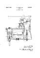
In the drawing the view depicts a carburetor in vertical section embodying the present invention. I
In this view the numeral 1 designates the float chamber of the carburetor which is contherein connected by suitable means, such as the leverage 10 with the throttle 5 in a, manner that when the throttle is opened or tramped the piston 9 is forced downwardly within its cylinder to provide an increased air pressure in the upper portion of the float chamber, thereby causing a momentary increase in the supply of gasoline to the atomizing jet 3. A breather hole 11 is provided in the upper portion of the float chamber to provide restricted communication with the atmosphere. The breather hole 11 is restricted in size to permit the creation of the abnormal prcssure when the piston 9 is depressed, but without obstructing the flow of fuel to and from the float chamber. The numeral 12 designates the feed passage or lineto the carburetor and the flow of fuel into the chamber is controlled by a needle valve 13 which is adjusted relative to its seat by the float 14 and the intermediate connection 15.
In the carburetor heretofore used, as the fuel feeds into the float chamber it carries with it bubbles of air and gaseous vapors which rise to the space above the liquid level in the float chamber, creating a pressure on the liquid and causing the level to rise in the atomizing jet thereby resulting in an unauthorized enrichment of the mixture and a consequent laboring of the engine, thebreather hole 11 being insuflicient tosatisfactorily relieve this increased condition when it occurs.
To overcome this objection, namely eliminating any unauthorized enrichment of the mixture by reason of bubbles of air or gaseous vapors entering with the feed 1n to the float chamber, the float chamber is dlvlded or partitioned from the feed discharge 12, the latter entering into a separate chamber 16 having a venting passage 17 opening to the atmosphere. The venting passage 17 is suflicient 1n size to permit the ready escape of vapors to the atmosphere. Consequently any air or gaseous vapors carried along with the fuel in the feed pipe and entering beneath the needle valve 13 will rise in the secondary or needle valve chamber 16 and escape to the atmosphere through the vent 17. The secondary chamber is herein shown as being formed integral with the float chamber, being separated therefrom by a partition 18 through which communication is established between the two chambers 1 and 16 by means of a port 19 disposed below the level of the fuel. The connection 15 between the float and the needle valve may extend through this port 19. The port 19 is obviously of such restriction as to insure the desired increase in the fuel supply to the jet 3 when the throttle is tramped.
Assuming the engine to be idling or operating at a normal speed and an acceleration is desired, the operator will tramp his throttle and by this act move the piston 9 downwardly to provide an increased and authorized pressure on the liquid in the float chamber which in turn causes the fuel to rise in the jet 3 so as to meet the, increased demand for fuel causedby the opening of the throttle and the consequent inrush of air past the jet. Thus the increased supply of.fuel to the jet occurs simultaneously with the opening of the throttle without interposing any lean mixture on which the engine will not satisfactorily respond.
Now with this improved carburetor when the throttle is tramped and the piston 9 moves downwardly, creating an abnormal pressure on the liquid within the float chamber the fuel will rise in the jet 3, as in the former construction and will .also back up into the secondary chamber 16, substantially as indicated by the dotted showing whereby the level of the fuel within the float chamber is quickly lowered and the float 1 L will drop so as to unseatthe needle valve 13 to start a replenishing flow of fuel into the carburetor practically at the same time. Consequently the carburetor is insured in having an ample supply of fuel to meet any sudden increased demands thereon for fuel.
Obviously, a tramping of the throttle always precedes an increased consumption of fuel and under the former carburetors thisincreased consumption continued in rogress for a. period preliminary to the nee le valve opening because of the float falling very slowly. With the improved carburetor wherein the fuel is backed up into the needle valve chamber, the float level is lowered almost immediately and the needle valve unseated so that the replenishing supply of fuel enters the carburetor substantially at the same time that the increased consumption begins. Further, after the engine has responded to the increased acceleration desired, the level of the fuel in. the jet has heretofore dropped more or less quickly to its normal, as the pres- 7 sure was relieved by the piston 9. W1th the improved carburetor the uel which backs up into the needle valve chamber will reflow to the float chamber, augmented by the replenishing supply from the needle valve, and sustain the jet level to a gradual tapering off to the normal, all tending toward an increased efficiency in engine operation'and behavior.
It is thus obvious that in addition to eliminating any objectionable pressure in the float chamber which would cause an unauthorized enrichment of the combustible mixture as supplied to the engine, (the air and gaseous vapors entering beneath the needle valve and therefore being segregated from the float chamber and prevented from being trapped therein to cause any resultant abnormal pressure with a resultant influence in the atomizing chamber,) that a replenishing flow of fuel from the supply tank to the carburetor is started practically at the same time with an increase in the demand.
In furtherance of this action the piston 9 is provided with a head having apertures 21 therein which are covered by a valving member or washer 22 upon the operating stroke of the piston. In the modification shown in the drawing the washer 22 is held in place by a retaining member or washer 23 attached to the piston rod 24 which extends through the piston head. This arrangement permits of slow and controlled passage of air through the openings 21 upon the upward stroke of the piston to the inoperative position whereby equalization of pressure between atmospheric and that in the chamber 1 may be aided. The pin and slot connection shown at 25 ensures a positive action upon the pis-' ton and the spring 26 aids'in returning the iston to the raised or inoperative position.
ommunication is made with the atmosphere through the breather ports 27 to permit of free operation of the piston in the cylinder 8 without building up pressure upon the upper side of the piston.
What is claimed is:
1. A carburetor having a float chamber, an atomizing chamber with a jet therein, and a needle valve chamber venting to the atmosphere and communicating with the float chamber beneath the liquid level therein, a fuel replenishing passage entering the needle valve chamber, a needle valve within the latter for controlling the fuel replenishment, a float withinthe float chamber connected to the needlevalve to operatively position the latter, said float chamber having a breather hole venting to the atmosphere, a throttle in the atomizing chamber, means for subjecting the fuel within the float chamber to an abnormal pressure for increasing the flow of fuel to the jet, and th1 ottle actuating means operatively connected to said first means.
2. A carburetor having a float chamber with a restricted communication to the atmosphere, an atomizing chamber with a jet therein, a needle valve chamber communicating with the float chamber beneath the liquid level therein, a fuel replenishing passage entering the needle valve chamber, a needle valve therein for controlling the re lenishment of fuel, a float within the float c amber connected to the needle valve to operatively position the latter, and a cylinder mounted on top of the float chamber in communication therewith, a piston movable downwardly within the cylinder for providing abnormal pressure on the liquid in the float chamber. 3. A carburetor provided with a float chamber having a restricted breather hole, an atomizing chamber with a jet therein, a needle valve chamber having a vent to the atmosphere larger than the breather hole and communicating with the float chamber beneath the liquid level therein, a fuel replenishing passage entering the needle valve chamber, a needle valve in said passage for controlling the fuel replenishment, a float within the float chamber connected to the needle valve to operatively position the latter, a throttle in the atomizing chamber, means for subjecting the fuel within the float chamber to an abnormal pressure for increasing the flow of fuel to the jet, and throttle actuating means operatively connected to said first means.
4. A carburetor having a float chamber, a needle valve chamber separated by a partition and connected therewith beneath the liquid level within the float chamber and also having a vent to the atmosphere, a float in the float chamber, a supply passage opening into the needle valve chamber, a needle valve connected through the partition to the float for controlling the flow of fuel through said passage, an atomizing jet connected to the float chamber, a cylinder connected to the upper portion of the float chamber, a piston within the cylinder for creating fluid pressure on the liquid within the float chamber, said float chamber having a breather hole in its upper part restricted in size to permit abnormal pressure being created by said piston, an atomizing chamber into which-the jet discharges, a throttle disposed in the atomizing chamber above the jet, and operative connections between the throttle and the piston for effecting operation of the piston upon opening of the throttle.
5. A carburetor comprising an atomizing jet, a needle valve chamber into which a fuel replenishing passage opens, and a chamber intermediate the needle valve chamber and the jet, said needle valve chamber venting to the atmosphere, a needle valve in the needle valve chamber for controlling the fuel entering through said passage,-a float for controlling said needle valve, and means associated with said intermediate chamber for momentarily subjecting the fuel therein to abnormal pressure for increasing the feed to the jet.
6. A carburetor comprising an atomizin jet, a needle valve chamber into which a fue replenishing passage opens, and a chamber intermediate the-needle valve chamber and the jet, a needle valve in the needle valve chamber for controlling the fuel entering through said passage, a float for controlling said needle valve, a cylinder in fluid communication with said intermediate chamber, a piston movable in said cylinder, a throttle for controlling the volume of gas passing said jet, and connecting means between said throttle and said piston for moving said piston for producing pressure in said intermediate chamber and momentarily subjecting the fuel therein to abnormal pressure for increasing the feed to the jet.
7 A carburetor comprising an atomizing jet, a needle valve chamber into which a fuel replenishing passage opens, a chamber intermediate the needle valve chamber and the jet, said needle valve chamber venting to the atmosphere, a needle valve in the needle valve chamber for controlling the fuel entering throughsaid passage, a float for controlling said needle valve, a cylinder in fluid communication with said intermediate chamber, a piston movable in said cylinder, a throttle for controlling the volume of gas passing said jet, and connecting means between said throttle and said piston for moving said piston for producing pressure in said'intermediate chamber and momentarily subjecting the fuel therein to abnormal pressure for increasing the feed to the jet.
8. A carburetor comprising an atomizing jet, a needle valve chamber into which a fuel replenishing passage opens, a chamber intermediate the needle valve chamber and the jet, said needle valve chamber venting to the atmosphere, a needle valve in the needle valve chamber for controlling the fuel entering through said passage, a float in said intermediate chamber connected to said needle valve for controlling the same, a cylinder having fluid communication with said intermediate chamber, a piston contained within said cylinder, a throttle for regulating the rate of passage of gas by said jet, operative connections between said throttle and said piston for actuating the piston on movement of said throttle, and means for urging said piston to for replenishing fuel in said float chamber, a
float contained in said chamber connected with means for regulating the flow of fluid through said passage into said chamber, :1 cylinder connected to said chamber, a piston contained in said cylinder, said cylinder being in communication with said float chamber upon one side of said piston and in communication with the atmosphere from the other side of said piston, a throttle in said atomizing chamber, operating means connecting said throttle with said piston for moving said piston when said throttle is open, and means connected-to said piston for returning the same to its in- V operative position, said piston having a passage for permitting flow of air therethrough on movement to the inoperative position.
HENRY HUEBER. ERWIN C. HORTON.
Priority Applications (1)
| Application Number | Priority Date | Filing Date | Title |
|---|---|---|---|
| US441292A US1852780A (en) | 1930-04-03 | 1930-04-03 | Carburetor |
Applications Claiming Priority (1)
| Application Number | Priority Date | Filing Date | Title |
|---|---|---|---|
| US441292A US1852780A (en) | 1930-04-03 | 1930-04-03 | Carburetor |
Publications (1)
| Publication Number | Publication Date |
|---|---|
| US1852780A true US1852780A (en) | 1932-04-05 |
Family
ID=23752318
Family Applications (1)
| Application Number | Title | Priority Date | Filing Date |
|---|---|---|---|
| US441292A Expired - Lifetime US1852780A (en) | 1930-04-03 | 1930-04-03 | Carburetor |
Country Status (1)
| Country | Link |
|---|---|
| US (1) | US1852780A (en) |
Cited By (2)
| Publication number | Priority date | Publication date | Assignee | Title |
|---|---|---|---|---|
| US2761647A (en) * | 1951-05-02 | 1956-09-04 | Ivan V Zeck | Valve for internal combustion engine carburetor |
| US2870778A (en) * | 1955-01-18 | 1959-01-27 | Controls Co Of America | Fuel valve with flow rate dependent upon combustion fan operation |
-
1930
- 1930-04-03 US US441292A patent/US1852780A/en not_active Expired - Lifetime
Cited By (2)
| Publication number | Priority date | Publication date | Assignee | Title |
|---|---|---|---|---|
| US2761647A (en) * | 1951-05-02 | 1956-09-04 | Ivan V Zeck | Valve for internal combustion engine carburetor |
| US2870778A (en) * | 1955-01-18 | 1959-01-27 | Controls Co Of America | Fuel valve with flow rate dependent upon combustion fan operation |
Similar Documents
| Publication | Publication Date | Title |
|---|---|---|
| US3322408A (en) | Carburetor | |
| US2036205A (en) | Carburetor | |
| US2142979A (en) | Fuel feeding system for internal combustion engines | |
| US2633342A (en) | Automotive carburetor | |
| US2162056A (en) | Carburetor | |
| US1956992A (en) | Carburetor attachment | |
| US1852780A (en) | Carburetor | |
| US4524744A (en) | Fuel system for combustion engine | |
| US2208702A (en) | Carburetor device | |
| US2208864A (en) | Carburetor device | |
| US1945180A (en) | Carburetor | |
| US2998232A (en) | Carburation devices for internal combustion engines | |
| US2785880A (en) | Carburetor | |
| US2649290A (en) | Carburetor | |
| US2034048A (en) | Carburetor | |
| US2615695A (en) | Carburetor | |
| US2513773A (en) | Supplementary feed device for internal-combustion engines | |
| US2199509A (en) | Carburetor accelerating means | |
| US2271113A (en) | Carburetor | |
| US2210055A (en) | Carburetor | |
| US2807449A (en) | Carburetor construction | |
| US4305368A (en) | Apparatus for venting fuel vapors | |
| US1881559A (en) | Accelerator pump | |
| US1977721A (en) | Carburetor | |
| US1845662A (en) | Carburetor |