US1852770A - Cooling system for internal combustion engines - Google Patents
Cooling system for internal combustion engines Download PDFInfo
- Publication number
- US1852770A US1852770A US452250A US45225030A US1852770A US 1852770 A US1852770 A US 1852770A US 452250 A US452250 A US 452250A US 45225030 A US45225030 A US 45225030A US 1852770 A US1852770 A US 1852770A
- Authority
- US
- United States
- Prior art keywords
- water
- tank
- radiator
- engine
- cooling system
- Prior art date
- Legal status (The legal status is an assumption and is not a legal conclusion. Google has not performed a legal analysis and makes no representation as to the accuracy of the status listed.)
- Expired - Lifetime
Links
Images
Classifications
-
- F—MECHANICAL ENGINEERING; LIGHTING; HEATING; WEAPONS; BLASTING
- F01—MACHINES OR ENGINES IN GENERAL; ENGINE PLANTS IN GENERAL; STEAM ENGINES
- F01P—COOLING OF MACHINES OR ENGINES IN GENERAL; COOLING OF INTERNAL-COMBUSTION ENGINES
- F01P3/00—Liquid cooling
- F01P3/22—Liquid cooling characterised by evaporation and condensation of coolant in closed cycles; characterised by the coolant reaching higher temperatures than normal atmospheric boiling-point
- F01P3/2207—Liquid cooling characterised by evaporation and condensation of coolant in closed cycles; characterised by the coolant reaching higher temperatures than normal atmospheric boiling-point characterised by the coolant reaching temperatures higher than the normal atmospheric boiling point
Definitions
- the invention relates to cooling systems for internalcombustion engines.
- One object of the invention is to provide an improved cooling system in which provision is made for retaining the full volume of water in the system after the water becomes heated and expands from the operation of the engine, so that the full supply of water will always be retained in the system.
- Another object of the invention is to provide a cooling system which is extremely efficient in operation in that it embodies means for retaining the water under a light pressure when it becomes heated to an unusual degree from the operation of the engine.
- a further object of the invention is to pro- Vide a system of the character last referred to which embodies a supply device that operates to prevent the building up of excessive pressure in the system.
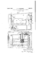
- Fig. 1 is a side elevation of an engine on a motor vehicle, equipped with the invention.
- Fig. 2 is a section on line 22 of Fig. 1.
- the invention is illustrated as applied to 0 a motor vehicle equipped with a water-jacketed internal combustion engine A, a radiator 1930. Serial No. 452,250.
- an engine-driven pump C receiving water through a pipe connection 0 from the lower portion of the radiator and adapted to circulate through the water jacket of the engine and through a return pipe 0 to the top of the radiator, all of which may be of usual construction, as well understood in the art.
- the radiator is provided with a cap 6 for the opening through which the radiator may be filled with water, and this cap is adapted to seal the opening to retain pressure in the radiator.
- An overflow pipe 10 extends from the inside of the top of the radiator downwardly, and is connected by a pipe-section 10 to a tank 11.
- Thepipe section 10 is connected'by a coupling 10 to the lower end of pipe 10 and by a union coupling 16 to a nipple 17 in the bottom of said tank.
- This exemplifies an overflow connection from the radiator by which all theoverflow will be conducted to, and retained by, the tank 11 in lieu of dis charging it from the system.
- Tank 11 is secured by brackets 12 to the front of the dash 13 under the engine hood 15, and is mounted at an elevation below the inlet or top of the overflow pipe 10, so that water entering the overflow pipe will flow by gravity into the tank 11. Normally, the tank 11 is open to atmosphere to permit the overflow water from the radiator to pass freely into it.
- the overflow tank When the water has become heated to a predetermined temperature, for example 170 Fahn, and has expanded, the excess caused by this expansion will passthrough the overflow 10 into, and be retained in, the tank 11.
- a predetermined degree for example 170 it is advantageousto close the overflow tank and keep the water under a light pressure, say two or three pounds, to raise its boiling point, so the water will not bubble and will be forced into intimate contact with the walls of the cooling jacket to cool more determined temperature, say 170, the tank and system will be closed to cause the water to be kept under the desired limited pressure.
- a cylindrical casing 20 is secured in and de pends from top 11 of tank 11.
- An annularly corrugated metallic bellows 21 has its lower end secured to a stem 22 which is secured by a nut 23 to a cross-wall at the lower end of casing 20 and an upwardly projecting stem 24 is secured'to the free upper end of the bellows.
- a valve 25 on stem 24 is adapted to engage a seat 26 formed on a sleeve 27 which is secured in a head 28 which is secured with the casing 20 by screws 29 to the top wall 11 of the tank 11.
- Sleeve 27 is provided with outlet-ports 30 through which air can pass to and from the tank 11 when the valve 27 is lowered or open. Openings 31 are formed in the casing 20 so that the water in the tank can circulate around the bellows. The latter are sealed so that when the temperature of the surrounding water rises, the bellows will expand to lift stem 24 and close valve 25, so as to prevent the escape of air from the tank to build up a pressure in the tank and entire cooling system.
- a flanged head 33 is fixed in the top 11 of a tank 11 and is provided with a seat 34 for a valve 35 which is normally held closed by a spring 36 and is adapted to be'opened by the pressure in tank 11 when it is suflicient to overcomethe force of the spring.
- the lower end of the stem 37 of valve 35 is guided in the head 33 and its upper end in a head 38 which is threaded to a cylindrical casing 39 which has its lower end secured to head 37.
- An elbow 40 connects an outlet port 41 in casing 39 to a downwardly extending pipe 42 through which air will be discharged when the valve 35 is opened by the pressure of fluid in the tank 11.
- a drain plug 44 is screwthreaded into a nipple45 welded to the bottom of the tank 11 to permit the water to be drained from the tank when desired.
- the operation of the improved cooling system will be as follows:
- the radiator is filled with Water, usually of normal temperature. WVhen the engine is operated, the temperature of the water will be raised which will cause the water to expand and the excess will pass through pipes 10, 10 into the overflow tank 11.
- the valve 25 for controlling the pressure in the overflow tank will be open to permit'the overflow water to flow by gravity from the radiator into tank 11.
- the radiation and cooling occur in the normal way,but the overflow caused by the expansion of the water will be collected in the tank 11 in lieu of being discharged from the cooling system-
- the heat in the water in the tank 11 will cause the bellows 21 to expand and to close the valve 25.
- the tank 11 will then be closed or sealed, so that a pressure 'will be created in the tank and in the entire cooling system as the temperature of the water is raised.
- This pressure of approximately two or three pounds, raises the boiling point of the Water, so that it will not bubble. Any bubbling of the water causes it to free itself from the cylinder walls, and by keeping the water under pressure, bubbling is prevented.
- this pressure will render the cooling more eflicient.
- the lower density of the air is counteracted by the pressure maintained in the cooling system.
- the motor is prevented from getting exceptionally hot, and'the Waste of water, which causes the vol ume of water in the system to be lessened, is prevented, and the engine will be operated under all conditions Without water-loss.
- the pressure in the system should become excessive, the pressure in the tank 11 will open the blow-off valve 35 and permit the escape of sufiicient air to reduce it to the maximum desired for eflicient cooling.
- the engine is stopped and Water in the cooling system has cooled oif, the water in the overflow tank will be drawn back to the radiator by the vacuum caused by the cooling and contraction of the water in the jacket with the result that the system will have a full charge of water, without loss through discharge.
- the cooling system will have a full charge of water.
- it has been found that in some instances, one eighth of the water is lost if the motor becomes excessively hot, and, as a result, the cooling system will be deficient when the motor is again started, unless the radiator is again filled.
- the invention exemplifies an improved cooling system in which the expansion of the water, resulting from the operation of the engine, will not cause any water-loss; in 1 which the cooling water is circulated under pressure when its temperature is beyond a predetermined point to increase its cooling efliciency; and in which provision is made to automatically prevent an excess pressure in the radiator and other parts of the cooling system.
- a radiator for receiving water from the jacket for the engine
- a tank connected to receive overflow from the radiator
- a valve controlled by the temperature of the overflow-water in the tank for closing said tank in order to permit pressure to be built up in the cooling system.
- a radiator for receiving water from the jacket for the engine
- a tank connected to receive overflow from the radiator
- a Valve in the tank controlled by the temperature of the overflow-water for closing the tank in order to permit pressure to be built up in the cooling system.
- a radiator for receiving water from the jacket of the engine, means connected to receive overflow from the radiator, a valve for closing said means to permit pressure to be built up in the cooling system, and a thermostat for controlling the operation of the valve.
- a radiator for receiving water from the jacket for the engine
- a tank connected to receive overflow from the radiator
- a valve for closing the tank to permit pressure to be built up in the cooling system
- a thermostat in the tank for operating the valve
- a radiator for receiving water from the jacket for the engine
- a tank connected to receive overflow from the radiator
- thermostatic means for closing the valve to permit pressure to be built up in the cooling system.
- a radiator for receiving water from the jacket for the engine, means connected to receive overflow from the radiator, means controlled by the temperature of the overflow-water for closing the overflow receiving means, and a blow-ofi valve connected to the overflow receiving means to permit the pressure to escape when it exceeds a predetermined point.
- a radiator for receiving water from the jacket for the engine
- a tank connected to receive overflow from the radiator
- means controlled by the temperature of the overflow-water for closing the tank means controlled by the temperature of the overflow-water for closing the tank
- a blow-oif valve connected to the tank to permit the pressure to escape when it exceeds a predetermined point.
- a radiator for receiving water from the jacket for the engine
- a tank connected to receive overflow from the radiator
- means controlled by the temperature of the overflow-water for closing the tank means controlled by the temperature of the overflow-water for closing the tank, and a blow-ofl valve to permit pressure in the system to escape when it exceeds a predetermined point.
- a radiator for receiving water from the jacket for the engine
- a tank connected to receive overflow from the radiator
- a normally open valve connected to the tank
- means controlled by the temperature of the overflow-water for closing the valve and means connected to the tank to permit pressure to escape when it exceeds a predetermined point.
Description
F. S. DUESENBERG COOLING SYSTEM FOR INTERNAL COMBUSTION ENGINES Aprii 5, 1932.
Filed May 14, 1950 jwenwr f MzK Patented Apr. 5, 1932 UNITED STATES PATENT OFFICE FREDERICK S. DUESENIBERG, OF INDIANAPOLIS, INDIANA, ASSIGNOR TO INDIANAPOLIS CORPORATION, OF INDIANAPOLIS, INDIANA, A CORPORATION OF DELAWARE COOLING SYSTEM FOR INTERNAL COMBUSTION ENGINES Application filed May 14,
The invention relates to cooling systems for internalcombustion engines.
In cooling systems for engines used onmotor-vehicles, it is now common I practice to discharge the excess water from the radiator. When the radiator is full of water and the engine is operated, the water becomes heated and expands, and, as a result, the excess is discharged from the system through the usual overflow pipe. This results in a water-loss which reduces the volume of water remaining in, and the cooling efliciencyof, the system.
One object of the invention is to provide an improved cooling system in which provision is made for retaining the full volume of water in the system after the water becomes heated and expands from the operation of the engine, so that the full supply of water will always be retained in the system.
In practice it has been found that when the engine is operating under a heavy load, as in hill climbing, or other conditions which cause abnormal temperature of the water, more efficient cooling is effected if the water is kept under suflicient pressure to raise itsboiling point.
Another object of the invention is to provide a cooling system which is extremely efficient in operation in that it embodies means for retaining the water under a light pressure when it becomes heated to an unusual degree from the operation of the engine.
A further object of the invention is to pro- Vide a system of the character last referred to which embodies a supply device that operates to prevent the building up of excessive pressure in the system.
Other objects ofthe invention will be apparent from a consideration of the following. The invention consists in the several novel features hereinafter set forth and more particularly defined by claims at the conclusion hereof. a
In thedrawings: Fig. 1 is a side elevation of an engine on a motor vehicle, equipped with the invention. Fig. 2 is a section on line 22 of Fig. 1.
The invention is illustrated as applied to 0 a motor vehicle equipped with a water-jacketed internal combustion engine A, a radiator 1930. Serial No. 452,250.
B, an engine-driven pump C receiving water through a pipe connection 0 from the lower portion of the radiator and adapted to circulate through the water jacket of the engine and through a return pipe 0 to the top of the radiator, all of which may be of usual construction, as well understood in the art. The radiator is provided with a cap 6 for the opening through which the radiator may be filled with water, and this cap is adapted to seal the opening to retain pressure in the radiator.
An overflow pipe 10 extends from the inside of the top of the radiator downwardly, and is connected by a pipe-section 10 to a tank 11. Thepipe section 10 is connected'by a coupling 10 to the lower end of pipe 10 and by a union coupling 16 to a nipple 17 in the bottom of said tank. This exemplifies an overflow connection from the radiator by which all theoverflow will be conducted to, and retained by, the tank 11 in lieu of dis charging it from the system. Tank 11 is secured by brackets 12 to the front of the dash 13 under the engine hood 15, and is mounted at an elevation below the inlet or top of the overflow pipe 10, so that water entering the overflow pipe will flow by gravity into the tank 11. Normally, the tank 11 is open to atmosphere to permit the overflow water from the radiator to pass freely into it.
When the water has become heated to a predetermined temperature, for example 170 Fahn, and has expanded, the excess caused by this expansion will passthrough the overflow 10 into, and be retained in, the tank 11. When, from the operation of the engine the temperature of the water rises above a predetermined degree, for example 170 it is advantageousto close the overflow tank and keep the water under a light pressure, say two or three pounds, to raise its boiling point, so the water will not bubble and will be forced into intimate contact with the walls of the cooling jacket to cool more determined temperature, say 170, the tank and system will be closed to cause the water to be kept under the desired limited pressure. A cylindrical casing 20 is secured in and de pends from top 11 of tank 11. An annularly corrugated metallic bellows 21 has its lower end secured to a stem 22 which is secured by a nut 23 to a cross-wall at the lower end of casing 20 and an upwardly projecting stem 24 is secured'to the free upper end of the bellows. A valve 25 on stem 24 is adapted to engage a seat 26 formed on a sleeve 27 which is secured in a head 28 which is secured with the casing 20 by screws 29 to the top wall 11 of the tank 11. Sleeve 27 is provided with outlet-ports 30 through which air can pass to and from the tank 11 when the valve 27 is lowered or open. Openings 31 are formed in the casing 20 so that the water in the tank can circulate around the bellows. The latter are sealed so that when the temperature of the surrounding water rises, the bellows will expand to lift stem 24 and close valve 25, so as to prevent the escape of air from the tank to build up a pressure in the tank and entire cooling system.
A flanged head 33 is fixed in the top 11 of a tank 11 and is provided with a seat 34 for a valve 35 which is normally held closed by a spring 36 and is adapted to be'opened by the pressure in tank 11 when it is suflicient to overcomethe force of the spring. The lower end of the stem 37 of valve 35 is guided in the head 33 and its upper end in a head 38 which is threaded to a cylindrical casing 39 which has its lower end secured to head 37. An elbow 40 connects an outlet port 41 in casing 39 to a downwardly extending pipe 42 through which air will be discharged when the valve 35 is opened by the pressure of fluid in the tank 11. A drain plug 44 is screwthreaded into a nipple45 welded to the bottom of the tank 11 to permit the water to be drained from the tank when desired.
The operation of the improved cooling system will be as follows: The radiator is filled with Water, usually of normal temperature. WVhen the engine is operated, the temperature of the water will be raised which will cause the water to expand and the excess will pass through pipes 10, 10 into the overflow tank 11. Normally, the valve 25 for controlling the pressure in the overflow tank will be open to permit'the overflow water to flow by gravity from the radiator into tank 11. The radiation and cooling occur in the normal way,but the overflow caused by the expansion of the water will be collected in the tank 11 in lieu of being discharged from the cooling system- When the temperature of the water is raised beyond the predetermined 7 point, the heat in the water in the tank 11 will cause the bellows 21 to expand and to close the valve 25. The tank 11 will then be closed or sealed, so that a pressure 'will be created in the tank and in the entire cooling system as the temperature of the water is raised. This pressure of approximately two or three pounds, raises the boiling point of the Water, so that it will not bubble. Any bubbling of the water causes it to free itself from the cylinder walls, and by keeping the water under pressure, bubbling is prevented. Thus, when the cooling water reaches the higher temperature, as when operating under a heavy load, or for any other cause, this pressure will render the cooling more eflicient. In operating the engine at high altitudes, the lower density of the air is counteracted by the pressure maintained in the cooling system. As a result, the motor is prevented from getting exceptionally hot, and'the Waste of water, which causes the vol ume of water in the system to be lessened, is prevented, and the engine will be operated under all conditions Without water-loss. If the pressure in the system should become excessive, the pressure in the tank 11 will open the blow-off valve 35 and permit the escape of sufiicient air to reduce it to the maximum desired for eflicient cooling. When the engine is stopped and Water in the cooling system has cooled oif, the water in the overflow tank will be drawn back to the radiator by the vacuum caused by the cooling and contraction of the water in the jacket with the result that the system will have a full charge of water, without loss through discharge. When the engine is again started, the cooling system will have a full charge of water. In practice, it has been found that in some instances, one eighth of the water is lost if the motor becomes excessively hot, and, as a result, the cooling system will be deficient when the motor is again started, unless the radiator is again filled.
The invention exemplifies an improved cooling system in which the expansion of the water, resulting from the operation of the engine, will not cause any water-loss; in 1 which the cooling water is circulated under pressure when its temperature is beyond a predetermined point to increase its cooling efliciency; and in which provision is made to automatically prevent an excess pressure in the radiator and other parts of the cooling system.
The invention is not to be understood as restricted to the details set forth, since these may be modified within the scopeof the aplily-i pended claims, without departing from the spirit and scope of the invention.
Having thus described the invention, what I claim as new and desire to secure by Letters Patent, is:
' 1. In a water cooling system for a water jacketed engine, the combination of a radiator for receiving water from the jacket for the engine, a tank connected to receive overflow from the radiator, and a valve controlled by the temperature of the overflow-water in the tank for closing said tank in order to permit pressure to be built up in the cooling system.
2. In a water cooling system for a water jacketed engine, the combination of a radiator for receiving water from the jacket for the engine, a tank connected to receive overflow from the radiator, and a Valve in the tank controlled by the temperature of the overflow-water for closing the tank in order to permit pressure to be built up in the cooling system.
8. In a water cooling system for a water jacketed engine, the combination of a radiator for receiving water from the jacket of the engine, means connected to receive overflow from the radiator, a valve for closing said means to permit pressure to be built up in the cooling system, and a thermostat for controlling the operation of the valve.
4. In a water cooling system for a water jacketed engine, the combination of a radiator for receiving water from the jacket for the engine, a tank connected to receive overflow from the radiator, a valve for closing the tank to permit pressure to be built up in the cooling system, and a thermostat in the tank for operating the valve.
5. In a water cooling system for a water jacketed engine, the combination of a radiator for receiving water from the jacket for the engine, a tank connected to receive overflow from the radiator, a normally open valve in the top of the tank, and thermostatic means for closing the valve to permit pressure to be built up in the cooling system.
6. In a cooling system for a water jacketed engine, the combination of a radiator for receiving water from the jacket for the engine, means connected to receive overflow from the radiator, means controlled by the temperature of the overflow-water for closing the overflow receiving means, and a blow-ofi valve connected to the overflow receiving means to permit the pressure to escape when it exceeds a predetermined point.
7. In a cooling system for a water jacketed engine, the combination of a radiator for receiving water from the jacket for the engine, a tank connected to receive overflow from the radiator, means controlled by the temperature of the overflow-water for closing the tank, and a blow-oif valve connected to the tank to permit the pressure to escape when it exceeds a predetermined point.
8. In a cooling system for a water jacketed engine, the combination of a radiator for receiving water from the jacket for the engine, a tank connected to receive overflow from the radiator, means controlled by the temperature of the overflow-water for closing the tank, and a blow-ofl valve to permit pressure in the system to escape when it exceeds a predetermined point.
9. In a cooling system for a water acketed engine, the combination of a radiator for receiving water from the jacket for the engine, a tank connected to receive overflow from the radiator, a normally open valve connected to the tank, means controlled by the temperature of the overflow-water for closing the valve, and means connected to the tank to permit pressure to escape when it exceeds a predetermined point.
Signed at Indianapolis, Indiana, this 28th day of April, 1930.
FREDERICK S. DUESENBERG.
Priority Applications (1)
| Application Number | Priority Date | Filing Date | Title |
|---|---|---|---|
| US452250A US1852770A (en) | 1930-05-14 | 1930-05-14 | Cooling system for internal combustion engines |
Applications Claiming Priority (1)
| Application Number | Priority Date | Filing Date | Title |
|---|---|---|---|
| US452250A US1852770A (en) | 1930-05-14 | 1930-05-14 | Cooling system for internal combustion engines |
Publications (1)
| Publication Number | Publication Date |
|---|---|
| US1852770A true US1852770A (en) | 1932-04-05 |
Family
ID=23795720
Family Applications (1)
| Application Number | Title | Priority Date | Filing Date |
|---|---|---|---|
| US452250A Expired - Lifetime US1852770A (en) | 1930-05-14 | 1930-05-14 | Cooling system for internal combustion engines |
Country Status (1)
| Country | Link |
|---|---|
| US (1) | US1852770A (en) |
Cited By (5)
| Publication number | Priority date | Publication date | Assignee | Title |
|---|---|---|---|---|
| US4167159A (en) * | 1977-04-29 | 1979-09-11 | Deere & Company | Pressurized liquid cooling system for an internal combustion engine |
| FR2554505A1 (en) * | 1983-11-03 | 1985-05-10 | Maschf Augsburg Nuernberg Ag | EVAPORATION COOLING SYSTEM FOR INTERNAL COMBUSTION ENGINES |
| US4574747A (en) * | 1983-12-02 | 1986-03-11 | Nissan Motor Co., Ltd. | Cooling system for automotive engine |
| US4677943A (en) * | 1986-03-03 | 1987-07-07 | Skinner Alan A | Automotive non-pressure cooling system |
| US20060112910A1 (en) * | 2004-11-26 | 2006-06-01 | Gen Ohzono | Vehicle |
-
1930
- 1930-05-14 US US452250A patent/US1852770A/en not_active Expired - Lifetime
Cited By (8)
| Publication number | Priority date | Publication date | Assignee | Title |
|---|---|---|---|---|
| US4167159A (en) * | 1977-04-29 | 1979-09-11 | Deere & Company | Pressurized liquid cooling system for an internal combustion engine |
| FR2554505A1 (en) * | 1983-11-03 | 1985-05-10 | Maschf Augsburg Nuernberg Ag | EVAPORATION COOLING SYSTEM FOR INTERNAL COMBUSTION ENGINES |
| US4584971A (en) * | 1983-11-03 | 1986-04-29 | Maschinenfabrik Augsburg-Nurnberg | Evaporative cooling system for internal combustion engines |
| US4574747A (en) * | 1983-12-02 | 1986-03-11 | Nissan Motor Co., Ltd. | Cooling system for automotive engine |
| US4677943A (en) * | 1986-03-03 | 1987-07-07 | Skinner Alan A | Automotive non-pressure cooling system |
| US20060112910A1 (en) * | 2004-11-26 | 2006-06-01 | Gen Ohzono | Vehicle |
| US7398746B2 (en) * | 2004-11-26 | 2008-07-15 | Yamaha Hatsudoki Kabushiki Kaisha | Vehicle |
| CN100445158C (en) * | 2004-11-26 | 2008-12-24 | 雅马哈发动机株式会社 | Vehicle |
Similar Documents
| Publication | Publication Date | Title |
|---|---|---|
| US2086441A (en) | Cooling system for internal combustion engines | |
| US3729020A (en) | Pressure relief and drain valve | |
| US1852770A (en) | Cooling system for internal combustion engines | |
| US4677943A (en) | Automotive non-pressure cooling system | |
| CN108730496A (en) | Cooling system for speed changing box and its cooling means and automobile | |
| US4787445A (en) | Hermetically sealed, relatively low pressure cooling system for internal combustion engines and method therefor | |
| US2528791A (en) | Pressure control apparatus for engine cooling systems | |
| RU2109148C1 (en) | Combination system of automatic control and regulation of internal combustion engine thermal conditions | |
| US4739824A (en) | Hermetically sealed, relatively low pressure cooling system for internal combustion engines and method therefor | |
| US1378070A (en) | Water-cooling system for internal-combustion motors | |
| US1258068A (en) | Power plant. | |
| US2176331A (en) | Circulatory cooling system for internal combustion engines | |
| US2332680A (en) | Cooling system for liquid jacketed engines | |
| US2327342A (en) | Cooling system | |
| US1376086A (en) | Automatic cooling system | |
| US1651156A (en) | Temperature control for internal-combustion engines | |
| US1306000A (en) | Cooling system | |
| US1772341A (en) | Automobile heating system | |
| US1521475A (en) | Circulating system | |
| US2899026A (en) | Cooling system for fluid operated brake | |
| US2011876A (en) | Engine cooling system | |
| US1643511A (en) | Cooling system for internal-combustion engines and method of operating the same | |
| US1181144A (en) | Cooling system. | |
| US1369639A (en) | Internal-combustion engine | |
| US2447592A (en) | Internal-combustion engine cooling system |