US1852746A - Telephone system - Google Patents
Telephone system Download PDFInfo
- Publication number
- US1852746A US1852746A US476549A US47654930A US1852746A US 1852746 A US1852746 A US 1852746A US 476549 A US476549 A US 476549A US 47654930 A US47654930 A US 47654930A US 1852746 A US1852746 A US 1852746A
- Authority
- US
- United States
- Prior art keywords
- relay
- line
- circuit
- spring
- current
- Prior art date
- Legal status (The legal status is an assumption and is not a legal conclusion. Google has not performed a legal analysis and makes no representation as to the accuracy of the status listed.)
- Expired - Lifetime
Links
Images
Classifications
-
- H—ELECTRICITY
- H04—ELECTRIC COMMUNICATION TECHNIQUE
- H04Q—SELECTING
- H04Q3/00—Selecting arrangements
Definitions
- FIG. 1 J. w. GOOD I ERHAM TELEPHONE SYSTEM Filed Aug. 20, 1950 3 Sheeis-Sheet l FIG. 1
- This invention relates to telephone systems and particularly to party-line systems in which service assessments are made by means of substation registers.
- the objects of the invention are to enable full selective signaling of subscribers of a party line employing substation registers, to safeguard the subscribers against false operation of the registers, and otherwise to im 0 prove systems of this type.
- this objection is overcome by providing means in the selector switch preceding the final selector for automatically reversing the talking battery connections when a call is extended to one of the parties on a party line whose terminals are reversed in the final selector multiple.
- the current flowing over the line as a called line will leave the subscribers register in such a position that, when he again initiates a call as a calling Serial No. 476,549.
- Figs. 1 and 2 disclose a portion of an automatic telephone system embodying the invention.
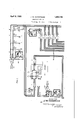
- Fig. 1 illustrates a four-party line appearing both in a line finder switch and in final selector switches. This figure also illustrates two single-party lines together with a line finder and a first selector switch and a group of final selector switches representedschematically.
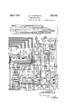
- Fig. 2 discloses a group selector switch in detail.
- Fig. 3 is an enlarged view of the circuit controlling commutator of the switch shown in Fig. 2.
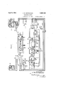
- Fig. 4 illustrates the invention when applied to a manual telephone system, the figure disclosing a party line appearing in an A operators position and also in a switching operators position.
- the party line 100 is provided with four substations M, J, R and TV, each equipped with an individual substation register such as the register 101. These registers respond to repeated reversals of current in the line during conversation to charge the calling subscriber.
- the substations M, J, R and W are also equipped with the respective ringers 103, 10 1-, 105 and 106, two of the ringers being connected to the tip conductor 107 and the other two to the ring conductor 108.
- the 'subscribers line 100 appears at the central ofiice in the contact bank of the line finder F, which serves to extend the line when a call is originated thereon.
- the line 100 also appears at the central office in the contact banks of four separate final selector switches S-3, S4, S-5 and S6.
- the line finder F extends calling lines to a selector switch S and also to a register sender 115.
- the calling subscriber by means of his impulse dial transmits impulses to cause the setting of the sender 115 in accordance with the wanted designation.
- the sender 115 controls the selector switch S to seize an idle trunk 116 leading to the group selector switch S1.
- the sender 115 controls the setting of the group selector S-1 to seize an idle trunk leading to the proper one of the final selector witches S2 to S6 inclusive.
- the final selector switch is controlled by the sender 115 to complete the extension of the connection to the called subscribers line, which may be either a single-party line 117 or a multi-party line 100.
- the line finder F and selector switches S, S1, S2, S3, S-4, S-5 and 55-6 may be of the panel power-drive type such as illustrated and described in the patent to Mc- Quarrie No. 1,177,044, granted March 28, 1916, and in the patent to Craft and Reynolds No. 1,123,696, granted January 5, 1915.
- the manner in which these switches are operated and controlled is disclosed in the patent to Kopp No. 1,589,402, granted June 22, 1926, and in the patent to Mills No. 1,504,261, granted August 12, 1924.
- the substation registers 101 may in general be the same as those disclosed in the patent to Beattie No. 912,268, granted February 9, 1909, and in the patent to Babcock No. 1,747,210 granted February 18, 1930. These registers are operated by reversals of current effected at the central office as disclosed and described in applicants Patent No. 1,814,248, issued July 14, 1931.
- the subscriber of line 110 wishes to converse with the subscriber at substation M on the party line 100.
- the initiation of the call on line 110 causes the operation of the line finder F to seize the line and extend it to the sender 115 and to the group selector S.
- the calling subscriber manipulates his dial 118 to record the wanted designation in the register sender 115.
- the sender proceeds to control the se lector switch S in accordance with the recorded designation to extend the calling line over an idle trunk 116 to the group selector switch S1.
- Relay 223 operates in this circuit and closes the following circuit for driving sequence switch 230 out of position 1 and into position 2: ground through the inner armature and front contact of relay 223, lower left contact of sequence switch spring 231, thence through the winding of the sequence switch magnet 230 to battery. lVith the sequence switch in position 2, the updrive power magnet 227 is energized causing the selector to move upward for brush selection.
- the circuit for magnet 227 may be traced from battery through the winding of said magnet, lower right and upper left contacts of sequence switch spring 240, inner front contact of relay 223 to ground.
- the commutator brush 243 encounters the metallic segments of commutator strip 247, and ground is intermittently connected to the tip side of the fundamental circuit, alternately closing and opening a short circuit around the stepping relay of the sender, causing this relay to release and reoperate.
- the shunt circuit may be traced from ground to the lower left and upper right contacts of spring 219, conductor 249, brush 243, commutator 247, conductor 250, upper right contact of spring 217, thence over conductor 238 to the tip side of the trunk 116.
- a parallel circuit is also traceable from the upper right and lower right contacts of spring 217, outer left front contact of relay 223, lower right and upper left contacts of spring 251, through the right winding of'relay 223 to battery.
- This latter circuit maintains relay 223 operated while the stepping relay in the sender is being shunted. ll hen the sender has been satisfied, the fundamental circuit is opened by the sender, and relay 223 is permitted to release, in turn opening the circuit of the .updrive magnet 227.
- the magnet 227 de energizes and permits the brushes to stop in a position to cause the subsequent trip ping of the selected set.
- Relay 223 on releasingv completes a circuit from ground through its inner back contact, upper right contact of sequence switch spring 231 and the winding of magnet 230, thus advancing the sequence switch out of position '2 and into position 3.
- relay 223 reoperates and closes a circuit over spring 231 for driving the sequence switch 230 out of position 3 and into position 4.
- the relay 223 In position 4 the relay 223 remains operated in a circuit from battery through its right winding, upper left and lower right contacts of spring 251, outer front contact of relay 223 through the lower contact of spring 217 and thence over the fundamental circuit as above traced.
- the updrive magnet 227 is again operated to cause the upward movement of the brush shaft to first trip the selected set of brushes and then to perform a group selecting operation.
- Thecircuit for the magnet 227 is traceable over the contacts of spring 240 and the inner front contact of relay 223.
- the brush shaft resumes its upward movement, the selected set of brushes is tripped due to the energized condition of the trip magnet 226 and are trailed over the contacts of the bank with which they cooperate.
- the fundamental circuit is intermittently shunted by means of a path traceable from the grounded conductor 249, brush 244, commutator 248, conductor 252, lower contacts of spring 201 to the tip side of the trunk 116.
- Relay 223 remains operated during the shunting of the stepping relay in the sender. When the sender has been satisfied, the fundamental circuit is opened and relay 223 releases to open the circuit of the magnet 227, causing the brushes to stop in operative relation to the selected group of trunks.
- Relay 223 at its back contact closes an obvious circuit for driving the sequence switch 230 out of position 4 and into position 5. As the sequence switch leaves position 4, the trip magnet 226 is deenergized.
- relay 223 In position 5 of the sequence switch, relay 223 reoperates in a circuit from battery through its left winding, lower contacts of spring 218 to ground. Relay 223 at its inner front contact closes a circuit for advancing the sequence switch out of position 5 and into position 6. If the first trunk in the selected group is busy, a ground condition exists on the test terminal thereof and the relay 223 is held in the following circuit: battery through the right winding of said relay, upper left and lower right contacts of spring 251, outer front contact of relay 223, left contacts of spring 220 to the grounded test terminal of the busy trunk. Relay 223 being operated in position 6 of the sequence switch, a circuit is again closed as above traced for the updrive magnet 227 and the selected brush set is driven upward over the group.
- relay 223 As soon as an idle trunk is encountered, the holding circuit of relay 223 is opened, but this relay does not immediately release, due to a second holding circuit which may be traced from battery through the left winding of said relay, left contacts of spring 218, centering commutator 246 and brush 242 to the grounded conductor 249.
- the brush 242 engages an insulating portion of the commutator, and relay 223 releases.
- Relay 223 opens the circuit of the magnet 227 and also closes an obvious circuit for driving the sequence switch out of position 6 and into position 7. After the sequence switch passes position 6% the selected trunk is maintained in a busycondition by means of a circuit from ground through the upper contacts of spring 220 to the test brush of the selector.
- relay 223 In position 7, relay 223 is operated in a circuit from battery through its right winding, the lower contacts of spring 217 to ground through the lower left and upper right contacts of spring 220. Relay 223 closes an 013- vious circuit for driving the sequence switch out of position 7 and into position 8. In position 8, relay 223 is held over a circuit traceable from battery through its right winding, upper left and lower right contacts of spring 251, outer front contact of relay 223, righthand contacts of spring 208, thence over the ring side of the selected trunk (such as the trunk 253) to ground at the final selector switch S-3.
- the tip side of the fundamen tal circuit is extended through the resistance 203 and the upper left and lower right con tacts of spring 207 through to battery in the final selector switch 8-3, and the ring side of the fundamental circuit is extended through the lower left and upper right contacts of spring 202, conductor 254, left-hand contacts of spring 240 through the inner front contact of relay 223 to ground.
- the final selector switch S3 is now oper ated under control of the sender 115 to select and seize the called subscribers line 100.
- ground potential is removed from the ring conductor and the relay 223 releases to close an obvious circuit for advancing the sequence switch 230 out of position 8 and into position 9.
- Relay 223 is operated in position 9 of the sequence switch over a circuit from battery through the right winding of said relay, upper contacts of spring-251, conductor 254, thence over the ring side of the fundamental circuit and re turning over the tip side through the resistance 203, lower right contact of spring 201, conductor 238, upper left contact of spring 217 to ground.
- Relay 223 at its inner front contact closes a circuit for driving the sequence switch out of position 9.
- the sequence switch moves through postion 10, and on leaving this position opens the circuit of re lay 225 which releases, causing the sequence switch to come to rest in position 11.
- the relay 222 operates in a circuit traceable from battery through the right winding of said relay, inner left contact of rela i 216, upper left winding of repeating 0011 200, uppermost contacts of spring 201, thence over the tip conductor through a loop closed at the switch S and returned over the ring conductor through the lowermost contacts of spring 202, lower left winding of coil 200, outer left contact of relay 216, left winding of relay 222 to ground.
- Relay 222 operates the relay 223 in a circuit from battery through the right winding of the latter relay, contact of relay 222, contact of relay 225, lower left contact of spring 233, upper right Contact of spring 2&0, upper right and lower left contacts of spring 219 to ground.
- Relay 223 closes an obvious circuit for driving the sequence switch out of position 11 and into position 12. As soon as the sequence switch reaches position 11 a holding circuit is established for relay 223 traceable from battery through the right winding of said relay, contacts of relays 222 and 225, spring 233, thence through the upper left contact of spring 2 10 to ground at the inner contact of relay 228.
- the connection is routed over theselector switch 3-3; when station J is called, the connection is routed over selector switch S- l; when station It is called, over selector S-5; and when station V is called, over the selector S6.
- selector switch Sl ringing current is always applied to the ring conductor of the connection and therefore always appears at the final selectors on the ring brush.
- the connections to switches S-5 and S6 are such that current flowing over the ring brush of these switches similarly flows over the ring conductor 108 of the line 100.
- the tip and ring conductors are reversed in the multiple, whereby ringing current flowing over the ring brush of the selector flows to the tip conductor 107 of the subscribers line.
- the talking current source at the right windings of repeating coil 200 is connected through to the subscribers line. If the line has been called over one of the final switches in whose multiple the called line is not reversed, the direction of current from the talking source is such that the negative pole of the battery is applied to the ring conductor of the line and the positive pole to the tip conductor of the line. This is the normal manner of connecting the talking source to a subscribers line and is the same as exists when current is applied to the line as a calling line through the windings of the line relay 109.
- the talking source of current in the selector S1 would be connected in such a manner that the positive pole of battery is connected to the ring conductor and the negative pole to the tip conductor.
- the subscribers register 1.01 would be left in a position such that when the subscriber subsequently initiated a call current through the line relay 109 would flow in the opposite direction, causing the register 101 to take a false operation.
- the selector switch S-l is equipped with a reversing relay 206 which is operated whenever a party line is seized as a called line over one of the final selector switches in whose multiples the tip and ring conductors are reversed.
- the means by which the relay 206 is selectively operated will now be described.
- the sequence switch 230 is in position 4 and subsequently moves into position 5. Since there are four groups of trunks in the switch S1, each group extending to a dilfercnt group of final selectors, the commutator brush 245 will, at the end of group selection, stand in either one of four quarters of the commutator 255. Referring to Fig. 3, it will be noted that commutator 255 is so fashioned as to provide insulating segments in the first and third quarters and conducting segments in the second and fourth quarters. As the switch S1 moves upward in its group selecting motion, the commutator brush 2 15 enters the first quarter where it encounters the insulating segment; therefore, no circuit is closed at this time.
- relay 206 When the brush 245 enters the third quarter of the commutator 255, it again engages an insulating segment, and, the shunt being removed, relay 206 operates in series with relay 224.
- the relay 206 remains unoperated whenever a selection is made in either of the two first groups, whereas this relay operates whenever a selection is made in the last two groups.
- the relay 206 when operated reverses the direction of current flow over the tip and ring conductors of the circuit extending to the final selector switches and thus insures that the flow of current in the called line is always in the same direction regardless of which party is being called.
- the selection of the proper source of ringing current for signaling the called subscriber is controlled by the commutator 255 in a manner similar to that involved in the selective operation of the reversing relay 206.
- the selection of ringing current takes place at a later time in the sequence of'operations, namely, when the sequence switch 230 reaches positions 11 and 12. With the sequence switch in position 11, a circuit is completed from battery through the winding of relay 224, lower contacts of spring 215, thence over the conductor 256 to the commutator 255.
- the commutator 255 will be grounded as above explained if the switchihas made a selection in either the second or fourth groups and will not be grounded if a selection has been made in the first or third groups.
- lay216 operates and locks in a circuit from battery to its right winding and contact, left contacts of spring 219to ground.
- Relay 216 completes a circuit from ground through its outer right contact and the upper left contact of spring 231 for driving the sequence switch out of position 12.
- the sequence switch on leaving position 12 opens the locking circuit of relay 216, and this relay releases, thereby permitting the sequence switch to stop in po- In position 14, the relay 216 is released and the ringing source 234 is disconnected at the lower left contact of spring 229.
- Interrupted ringing of the called subs-cribers bell is now effected by means of a circuit from the source 234 through the interrupter 236, upper con tacts of spring 229, and thence as above traced over the subscribers line to ground through the ringer 103.
- the ringing relay 225 When the called subscriber answers, the ringing relay 225 operates in the well-known manner and opens the circuit of relay 223, permitting this latter relay to release.
- the relay 223 disconnects the ringing source from the subscribers line and closes an obvious circuit for driving the sequence switch 230 out of position 14 and into position 15, causing the release of relay 224. 'VVhen the sequence switch reaches position 14%, relay 223 reoperates in a circuit from battery through its left winding, lower contacts of spring 218 to ground. Relay 223 closes an obvious circuit for driving a sequence switch out of position 15 and into the talking position 16.
- the circuit for supplying talking current to the called line may now be traced from the free pole of battery through the lower right winding of repeating coil 200, supervisory relay 205, upper front contact of relay 206, lower contacts of spring 207, thence over the tip side of the trunk 253 through the selector S-3 to the ring conductor of the line 100 through the loop at the substation and returning over the tip conductor of line 100, thence over the ring side of the trunk 253, upper contacts of spring 208, inner lower front contact of relay 206, through the upper right winding of coil 200 to the grounded pole of battery.
- Relay 205 operates in this circuit and closes a circuit from ground through its contact, upper contacts of spring 210, left winding of relay 216 to battery.
- the relay 216 operates and reverses the direction of current flow through the windings of relay 222 and the left windings of coil 200 to the trunk 116. This reversal of current may be utilized in the selector S to initiate the operation of the reversing mechanism for operating the substation register 120 at the calling subscribers station. The apparatus is now in condition for conversation.
- the subscribers replace their receivers on the switchhooks.
- the replacement of the called subscribers receiver opens the circuit of relay 205 which releases and causes the release of relay 216.
- the apparatus has now been restored to normal, and the called subscribers line 100 released.
- the message register 101 at the substation A is left in such a position, due to the direction of current flow from the selector switch S1, that when this party again initiates a call his register will not be falsely operated by current flowing through the windings of the line relay 109.
- a selector switch S1 is operated to choose a trunk 260 extending to the final selector switch S2. This trunk will be selected in a group at the switch S-l so located that the relay 206 does not operate to reverse the direction of current.
- the two-party line 400 appears in the jack 403 at an A operators position and also appears in the jacks 405 and 406 at a B operators position.
- the line 400 is provided with two substations M-1 and J-l, each of which is equipped with a substation register 424 similar to those hereinbefore mentioned.
- the terminals of the parties M1 and J1 are reversed in their respective jacks 405 and 406 to permit full selective ringing of the apparatus.
- the subscriber of line 401 desires to hold conversation with the subscriber at substation M1.
- the A operator responds to the initiation of the call by inserting the plug 425 of her cord circuit A into jack 402 of the calling line.
- the connection is extended in any well-known manner to the operators cord circuit B at the completing position.
- the extension of the connection to the cord circuit B results in the closure of a circuit from battery at the A position over one side of the trunk 427, through the lower left winding of repeating coil 422, windings of relay 423, upper left winding of coil 422 over the other side of the trunk to ground.
- Relay 423 operates in this circuit.
- the B operator in response to the instruction from the A operator inserts the plug 412 of her cord circuit in the jack 405 of the called station M1. This results in the closure of a circuit from battery to the marginal relay 415, relay 414, through the sleeve of the plug and jack, over conductor 426, through the winding of cut-off relay 410 to ground. Helay 410 operates and disconnects the line relay 409. Relay 414 operates, and, since no added resistance is included in the sleeve circuit, the marginal relay 415 also operates. Relay 414 closes a circuit from battery through the lamp 413, winding of relay 416 to ground at the contact of relay 414.
- Relay 416 operates, and in so doing closes a circuit from battery through the winding of relay 418, back contact of relay 417, contact of relay 430, inner lower contact of relay 416, contact of relay 423, winding of relay 416 to ground at the contact of relay 414.
- Relay 418 operates in this circuit, relay 416 remains operated, and the lamp 413 is shunted and remains extinguished.
- a parallel path also extends through the winding of relay 417, but this relay being shunted at the contaets of relay 430 remains deenergized.
- Relay 418 closes the ringing circuit from the source 419, interrupter 431, relay 430, lower front contact of relay 418, ring conductor of the trunk B and thence to the tip conductor 432, through the ringing relay 434 at the substation M1, thence over the ring conductor 433 through the jack 405 to the tip side of the cord B, upper contacts of relays 416 and 418 to ground.
- lVhen relay 434 operates, the ringing current is applied to the substation bell, and the called party is signaled.
- the direct bridge across the line causes the operation of the tripping relay 430, which removes the shunt and permits relay 417 to operate in series with relay 418.
- Relay 417 closes a circuit from battery through its front contact and winding and thence as above traced to ground at the contact of relay 414. This circuit shunts the relay 418 which releases and. disconnects ringing current from the called line.
- relay 415 As soon as relay 415 is operated, a circuit is completed from ground to the contact of said relay, winding of reversing relay 420 to battery.
- the circuit for supplying talking current to the called line may be traced from the free pole of battery, lower right winding of coil 422, winding of supervisory relay 421, upper :front contact of relay 420, upper back con tact of relay 418, upper contact of relay 416, thence through the plug and jack and over the ring conductor of the subscribers line to the substation loop and returning over the tip conductor, thence to the ring conductor of the cord B, lower back contact of relay 418, lower front contact of relay 420, upper right winding of coil 422 to ground.
- Relay 420 reverses the direction of current flow over the tip and ring conductors of the cord circuit B, in order to compensate for the reversal of the tip and ring conductors of the line 400 at the jack 405. This insures that current flowing over the called line will leave the register 424 in such a position that when the party M-l subsequently initiates a call the regi ter will not be falsely operated by current flowing through the winding of the line relay 409.
- Supervisory relay 421 operates and shunts the upper high resistance winding oi"- the relay 423. This causes the actuation of a supervisory signal at the A operators position to advise her that the called subscriber has answered.
- the calling subscriber may be charged for the service by means of a substation register located at his substation (not shown in the drawings).
- the substation register at the calling substation is operated by means of a reversing mechanism illustrated in the cord circuit A. F or a more complete disclosure of the manner in which these registers are operated, reterence is made to the patent to J. W. Gooderham 1,7 38,294, granted December 3, 1929.
- Vhat is claimed is:
- a subscribers line having a plurality of stations thereon, switching means for extending a connection to said line, means for si naling a desired station, a source of supplying talking current to said line, reversing means for changing the direction of current flow in said line, and means effective according to the station called for operating said reversing means.
- a subscribers line having a plurality of stations thereon, switching means for extending connections to said line, said line having a separate branch for each of said stations, means for selectively signaling said stations, a battery associated with said switching means for supplying talking current to said line, means for reversing the connections of said battery to change the direction of current flow in said line, and means eflective according to the branch over which the connection is extended to said line for operating said reversing means.
- a subscribers line having a plurality of stations thereon, an
- automatic switch means for operating said switch to selectivelyextend a connection to said line, means associated with said line for selectively signaling the subscribers thereon, a battery associated with said switch for applying talking current to said line, and means dependent upon the party called for reversing the flow of current over said line.
- a subscribers line having two stations thereon, automatic switches, the talking conductors of said line having two appearances in the terminals of said switches, the appearance of saidconductors in one set of ter inals being reversed with respect to the appearance in the other set of terminals, means for calling one of said parties by extending a connection to the line through one of said sets of terminals, a battery for supplying the line with talking current in a given direction over the extended connection, means for calling the other party by extending a connection to the line through the other set of terminals, and means efiective when the second party is called for reversing the direction of current flow from said battery to the line.
- a subscribers line having a plurality of stations thereon, means responsive to the initiation of a call by one of said stations for causing talking current to flow in a given direction in said line, automatic switches for extending a connection to said line as a called line, the conductors of said line appearing in a plurality of sets of terminals in said switches, said conductors being reversed at some of said terminals with respect to others, a source for supplying talking current to said line when called, and means depending upon the set of terminals over which a connection is extended to said line for changing the connections of said source to insure the flow of current in said line in the same direction when called as when callin 8.
- a subscribers line having a plurality of stations thereon, a message register at each of said stations responsive to the flow of current in said line, switching means for extending a connection to the line, means for signaling a desired station, a source for supplying current to said line, and means for reversing the flow of current from said source according to which of said stations is being called.
- a subscribers line having a plurality of stations thereon, message registers, one for each of said stations and responsive to reversals of current in the line, means efliective when one of said stations initiates a call for causing the flow of current in the line in a given direction, means for extending a connection to said line as a called line, a source for supplying current to said line when called, and means depending upon the party called for so controlling the flow of current in said line that the direction is the same as when the line is calling.
- a subscribers line having two stations thereon, registers, one at each of said stations responsive to reversals of current in the line, means eiiective when either of said stations initiates a call for causing the flow of current over the line in a given direction, means for periodically reversing the flow of current in the line during conversation to cause the repeated actuation of the calling subscribers register, automatic.
- switches said line appearing in two sets of terminals in said switches, the conductors of said line being reversed at one set of terminals with respect to the other, means for operating said switches to extend a connection over either of said sets of terminals to said line as a called line, means for supplying talking current to said line as a called line, and means efi'ective according to the set of terminals over which the connection is extended to the line for controlling the flow of current over said line such that the direction I is the same as when the line is calling.
Description
April'5, 1932.
J. w. GOOD I ERHAM TELEPHONE SYSTEM Filed Aug. 20, 1950 3 Sheeis-Sheet l FIG. 1
III
v un g 7 PP;
v E r: 7
I i 8 5 C) IN VE N TOE J W GOODERHAM April 5, 1932. J. w. GOODERHAM I TELEPHONE SYSTEM Filed Aug. 20, 1930 3 Sheets-Sheet IIIIIIIIHHI lNVENTOR J, W GOaDERHAM OWN April 1932- J. w. GOODERHAM 1,852,746
TELEPHONE SYSTEM Filed Aug. 20, 1930 3 Sheets-Sheet 3 a n N 4 Q i I I-H I 8 HI L S v H \l 1H w //VVEN7'0/? BY J. WGOODERHAM Patented Apr. 5, 1932 UNITED STATES PATENT OFFICE JOHN W: GOODERHAM, OF LARCI-IMONT, NEW YORK, ASSIGNOR TO BELL TELEPHONE LABORATORIES, INCORPORATED, OF YORK NEW YORK, N. Y., A CORPORATION OF NEW TELEPHONE SYSTEM Application filed August 20, 1930.
This invention relates to telephone systems and particularly to party-line systems in which service assessments are made by means of substation registers.
The objects of the invention are to enable full selective signaling of subscribers of a party line employing substation registers, to safeguard the subscribers against false operation of the registers, and otherwise to im 0 prove systems of this type.
It has been proposed heretofore to charge the subscriber for his telephone service by means of a register located at the substation and operated periodically during the conver- 5 sation by reversals of current in the subscribers line. It has also been proposed to selectively signal the subscribers on a fourparty line by giving the line an appearance in four separate final selector switches, one for each party. The connection is extended through the proper one of the final selectors over a preceding selector switch. Ringing current for signaling the subscribers of the party line is applied from the preceding switch and consists of both positive and negative polarities. By applying either of these polarities to a given side of the line at the preceding switch and by reversing the multiple connections of two of the parties in the terminal bank of the final switches, it is possible to obtain a full selective signaling system. When one of the parties whose terminals are reversed is called, the talking current flowing over his line leaves the register in a certain position. When thereafter the same subscriber initiates a call, current from the central oifice battery will flow over his line in the opposite direction, causing a false operation of his substation register.
According to the present invention, this objection is overcome by providing means in the selector switch preceding the final selector for automatically reversing the talking battery connections when a call is extended to one of the parties on a party line whose terminals are reversed in the final selector multiple. By so doing, the current flowing over the line as a called line will leave the subscribers register in such a position that, when he again initiates a call as a calling Serial No. 476,549.
party, current flowing over his line from the central oifice battery will not cause the false operation of his register.
By a modification of the invention, the same result is accomplished in a manual system by providing a distinctive condition in the sleeve circuit for those subscribers whose connections are reversed in the calling multiple. This distinctive condition serves to op erate a relay in the operators cord circuit which reverses the connections of the battery that furnishes the talking current.
In the drawings, Figs. 1 and 2 disclose a portion of an automatic telephone system embodying the invention. Fig. 1 illustrates a four-party line appearing both in a line finder switch and in final selector switches. This figure also illustrates two single-party lines together with a line finder and a first selector switch and a group of final selector switches representedschematically. Fig. 2 discloses a group selector switch in detail. Fig. 3 is an enlarged view of the circuit controlling commutator of the switch shown in Fig. 2. Fig. 4 illustrates the invention when applied to a manual telephone system, the figure disclosing a party line appearing in an A operators position and also in a switching operators position.
The party line 100 is provided with four substations M, J, R and TV, each equipped with an individual substation register such as the register 101. These registers respond to repeated reversals of current in the line during conversation to charge the calling subscriber. The substations M, J, R and W are also equipped with the respective ringers 103, 10 1-, 105 and 106, two of the ringers being connected to the tip conductor 107 and the other two to the ring conductor 108. The 'subscribers line 100 appears at the central ofiice in the contact bank of the line finder F, which serves to extend the line when a call is originated thereon. The line 100 also appears at the central office in the contact banks of four separate final selector switches S-3, S4, S-5 and S6. The appearance of the tin and ring conductors of line 100 in the banks of switches S3 and S& is reversed with respect to the appearance of these conductors in the banks of switches S5 and S6. The purpose of this is to enable fullselective ringing of the substations as will be explained more fully hereinafter.
The line finder F extends calling lines to a selector switch S and also to a register sender 115. The calling subscriber by means of his impulse dial transmits impulses to cause the setting of the sender 115 in accordance with the wanted designation. Thereupon, the sender 115 controls the selector switch S to seize an idle trunk 116 leading to the group selector switch S1. Following this, the sender 115 controls the setting of the group selector S-1 to seize an idle trunk leading to the proper one of the final selector witches S2 to S6 inclusive. Qhereupon the final selector switch is controlled by the sender 115 to complete the extension of the connection to the called subscribers line, which may be either a single-party line 117 or a multi-party line 100.
The line finder F and selector switches S, S1, S2, S3, S-4, S-5 and 55-6 may be of the panel power-drive type such as illustrated and described in the patent to Mc- Quarrie No. 1,177,044, granted March 28, 1916, and in the patent to Craft and Reynolds No. 1,123,696, granted January 5, 1915. The manner in which these switches are operated and controlled is disclosed in the patent to Kopp No. 1,589,402, granted June 22, 1926, and in the patent to Mills No. 1,504,261, granted August 12, 1924.
The manner in which full selective ringing of the called substations is secured in a system of this kind is disclosed in the patent to Reeves No. 1,218,804, granted March 13, 1917.
The substation registers 101 may in general be the same as those disclosed in the patent to Beattie No. 912,268, granted February 9, 1909, and in the patent to Babcock No. 1,747,210 granted February 18, 1930. These registers are operated by reversals of current effected at the central office as disclosed and described in applicants Patent No. 1,814,248, issued July 14, 1931.
A detailed description will now be given, and it will be assumed for this purpose that the subscriber of line 110 wishes to converse with the subscriber at substation M on the party line 100. The initiation of the call on line 110 causes the operation of the line finder F to seize the line and extend it to the sender 115 and to the group selector S. The calling subscriber manipulates his dial 118 to record the wanted designation in the register sender 115. The sender proceeds to control the se lector switch S in accordance with the recorded designation to extend the calling line over an idle trunk 116 to the group selector switch S1.
Upon the seizure of the switch S1, a circuit is completed from battery through the right winding of relay 223, lower left contact of sequence switch spring 217, conductor 238, lower right contact of sequence switch spring 201, resistance 203, thence over the tip conductor of trunk 116 through the tip brush of selector S and thence through a relay in the sender 115 (not shown) and returning over the ring brush of selector S and the ring conductor of trunk 116, resistance 204, upper right and upper left contacts of sequence switch spring 202 to ground. This circuit constitutes the wellknown fundamental circuit of the panel system and is more fully described in the reference patents above cited. Relay 223 operates in this circuit and closes the following circuit for driving sequence switch 230 out of position 1 and into position 2: ground through the inner armature and front contact of relay 223, lower left contact of sequence switch spring 231, thence through the winding of the sequence switch magnet 230 to battery. lVith the sequence switch in position 2, the updrive power magnet 227 is energized causing the selector to move upward for brush selection. The circuit for magnet 227 may be traced from battery through the winding of said magnet, lower right and upper left contacts of sequence switch spring 240, inner front contact of relay 223 to ground. As the brushes 241 of the selector S-1 move upward, the commutator brush 243 encounters the metallic segments of commutator strip 247, and ground is intermittently connected to the tip side of the fundamental circuit, alternately closing and opening a short circuit around the stepping relay of the sender, causing this relay to release and reoperate. The shunt circuit may be traced from ground to the lower left and upper right contacts of spring 219, conductor 249, brush 243, commutator 247, conductor 250, upper right contact of spring 217, thence over conductor 238 to the tip side of the trunk 116. A parallel circuit is also traceable from the upper right and lower right contacts of spring 217, outer left front contact of relay 223, lower right and upper left contacts of spring 251, through the right winding of'relay 223 to battery. This latter circuit maintains relay 223 operated while the stepping relay in the sender is being shunted. ll hen the sender has been satisfied, the fundamental circuit is opened by the sender, and relay 223 is permitted to release, in turn opening the circuit of the .updrive magnet 227. The magnet 227 de energizes and permits the brushes to stop in a position to cause the subsequent trip ping of the selected set. Relay 223 on releasingv completes a circuit from ground through its inner back contact, upper right contact of sequence switch spring 231 and the winding of magnet 230, thus advancing the sequence switch out of position '2 and into position 3. In position 3 of the sequence switch, a circuitis closed for the trip magnet 226 traceable from battery through the winding of said magnet, lower contacts of spring 219 to ground.
WVhen the fundamental circuit is again closed at the sender, relay 223 reoperates and closes a circuit over spring 231 for driving the sequence switch 230 out of position 3 and into position 4. In position 4 the relay 223 remains operated in a circuit from battery through its right winding, upper left and lower right contacts of spring 251, outer front contact of relay 223 through the lower contact of spring 217 and thence over the fundamental circuit as above traced. The updrive magnet 227 is again operated to cause the upward movement of the brush shaft to first trip the selected set of brushes and then to perform a group selecting operation. Thecircuit for the magnet 227 is traceable over the contacts of spring 240 and the inner front contact of relay 223. hen the brush shaft resumes its upward movement, the selected set of brushes is tripped due to the energized condition of the trip magnet 226 and are trailed over the contacts of the bank with which they cooperate. During the group selecting movement of the switch, the fundamental circuit is intermittently shunted by means of a path traceable from the grounded conductor 249, brush 244, commutator 248, conductor 252, lower contacts of spring 201 to the tip side of the trunk 116. Relay 223 remains operated during the shunting of the stepping relay in the sender. When the sender has been satisfied, the fundamental circuit is opened and relay 223 releases to open the circuit of the magnet 227, causing the brushes to stop in operative relation to the selected group of trunks. Relay 223 at its back contact closes an obvious circuit for driving the sequence switch 230 out of position 4 and into position 5. As the sequence switch leaves position 4, the trip magnet 226 is deenergized.
In position 5 of the sequence switch, relay 223 reoperates in a circuit from battery through its left winding, lower contacts of spring 218 to ground. Relay 223 at its inner front contact closes a circuit for advancing the sequence switch out of position 5 and into position 6. If the first trunk in the selected group is busy, a ground condition exists on the test terminal thereof and the relay 223 is held in the following circuit: battery through the right winding of said relay, upper left and lower right contacts of spring 251, outer front contact of relay 223, left contacts of spring 220 to the grounded test terminal of the busy trunk. Relay 223 being operated in position 6 of the sequence switch, a circuit is again closed as above traced for the updrive magnet 227 and the selected brush set is driven upward over the group.
As soon as an idle trunk is encountered, the holding circuit of relay 223 is opened, but this relay does not immediately release, due to a second holding circuit which may be traced from battery through the left winding of said relay, left contacts of spring 218, centering commutator 246 and brush 242 to the grounded conductor 249. When the brushes are accurately centered on the terminals, the brush 242 engages an insulating portion of the commutator, and relay 223 releases. Relay 223 opens the circuit of the magnet 227 and also closes an obvious circuit for driving the sequence switch out of position 6 and into position 7. After the sequence switch passes position 6% the selected trunk is maintained in a busycondition by means of a circuit from ground through the upper contacts of spring 220 to the test brush of the selector.
In position 7, relay 223 is operated in a circuit from battery through its right winding, the lower contacts of spring 217 to ground through the lower left and upper right contacts of spring 220. Relay 223 closes an 013- vious circuit for driving the sequence switch out of position 7 and into position 8. In position 8, relay 223 is held over a circuit traceable from battery through its right winding, upper left and lower right contacts of spring 251, outer front contact of relay 223, righthand contacts of spring 208, thence over the ring side of the selected trunk (such as the trunk 253) to ground at the final selector switch S-3. The tip side of the fundamen tal circuit is extended through the resistance 203 and the upper left and lower right con tacts of spring 207 through to battery in the final selector switch 8-3, and the ring side of the fundamental circuit is extended through the lower left and upper right contacts of spring 202, conductor 254, left-hand contacts of spring 240 through the inner front contact of relay 223 to ground.
The final selector switch S3 is now oper ated under control of the sender 115 to select and seize the called subscribers line 100. After selection has been completed by the final switch, ground potential is removed from the ring conductor and the relay 223 releases to close an obvious circuit for advancing the sequence switch 230 out of position 8 and into position 9. Relay 223 is operated in position 9 of the sequence switch over a circuit from battery through the right winding of said relay, upper contacts of spring-251, conductor 254, thence over the ring side of the fundamental circuit and re turning over the tip side through the resistance 203, lower right contact of spring 201, conductor 238, upper left contact of spring 217 to ground. Relay 223 at its inner front contact closes a circuit for driving the sequence switch out of position 9. The sequence switch moves through postion 10, and on leaving this position opens the circuit of re lay 225 which releases, causing the sequence switch to come to rest in position 11.
As soon as trunk closure takes place in the selector Switch S, the relay 222 operates in a circuit traceable from battery through the right winding of said relay, inner left contact of rela i 216, upper left winding of repeating 0011 200, uppermost contacts of spring 201, thence over the tip conductor through a loop closed at the switch S and returned over the ring conductor through the lowermost contacts of spring 202, lower left winding of coil 200, outer left contact of relay 216, left winding of relay 222 to ground. Relay 222 operates the relay 223 in a circuit from battery through the right winding of the latter relay, contact of relay 222, contact of relay 225, lower left contact of spring 233, upper right Contact of spring 2&0, upper right and lower left contacts of spring 219 to ground. Relay 223 closes an obvious circuit for driving the sequence switch out of position 11 and into position 12. As soon as the sequence switch reaches position 11 a holding circuit is established for relay 223 traceable from battery through the right winding of said relay, contacts of relays 222 and 225, spring 233, thence through the upper left contact of spring 2 10 to ground at the inner contact of relay 228.
he switch is now in condition to apply ringing current to the called subscribers line. Before proceeding with the detailed description of the application of ringing current, a general explanation will be given of the method by which full selective ringing is attained without endange ing the false operation of a subscribers substation register. To secure full selective signaling of the parties, the lines, such as line 100, are segregated to appear in four different groups of final selector switches, one appearance for each substation on the line. T he line 100, for example, appears in the final selectors S-B, S4i, S5 and S6. When the substation M is called, the connection is routed over theselector switch 3-3; when station J is called, the connection is routed over selector switch S- l; when station It is called, over selector S-5; and when station V is called, over the selector S6. At the selector switch Sl, ringing current is always applied to the ring conductor of the connection and therefore always appears at the final selectors on the ring brush. In the multiple of the final selectors, the connections to switches S-5 and S6 are such that current flowing over the ring brush of these switches similarly flows over the ring conductor 108 of the line 100. In the switches S3 and S-, however, the tip and ring conductors are reversed in the multiple, whereby ringing current flowing over the ring brush of the selector flows to the tip conductor 107 of the subscribers line.
By applying either positive or negative ring-' ing current at the switch Sl, four signal ing conditions are possible, namely, positive or negative ringing current on the tip conductor of the line or positive or negative ringing current on the ring conductor of the line.
After the called subscriber has been signaled and has answered the call, the talking current source at the right windings of repeating coil 200 is connected through to the subscribers line. If the line has been called over one of the final switches in whose multiple the called line is not reversed, the direction of current from the talking source is such that the negative pole of the battery is applied to the ring conductor of the line and the positive pole to the tip conductor of the line. This is the normal manner of connecting the talking source to a subscribers line and is the same as exists when current is applied to the line as a calling line through the windings of the line relay 109. On the other hand, if the called line is seized over one of the final selectors S3 or S4 in whose multiples the tip and ring conductors are reversed and if no provision were made otherwise, the talking source of current in the selector S1 would be connected in such a manner that the positive pole of battery is connected to the ring conductor and the negative pole to the tip conductor. With current flowing in this direction, the subscribers register 1.01 would be left in a position such that when the subscriber subsequently initiated a call current through the line relay 109 would flow in the opposite direction, causing the register 101 to take a false operation. To avoid this, the selector switch S-l is equipped with a reversing relay 206 which is operated whenever a party line is seized as a called line over one of the final selector switches in whose multiples the tip and ring conductors are reversed. The means by which the relay 206 is selectively operated will now be described.
At the time group selection is made in the selector switch -1, the sequence switch 230 is in position 4 and subsequently moves into position 5. Since there are four groups of trunks in the switch S1, each group extending to a dilfercnt group of final selectors, the commutator brush 245 will, at the end of group selection, stand in either one of four quarters of the commutator 255. Referring to Fig. 3, it will be noted that commutator 255 is so fashioned as to provide insulating segments in the first and third quarters and conducting segments in the second and fourth quarters. As the switch S1 moves upward in its group selecting motion, the commutator brush 2 15 enters the first quarter where it encounters the insulating segment; therefore, no circuit is closed at this time. When the brush 245 enters the second quarter it engages a metallic segment of the commutator 255, and a circuit is completed from ground through brush 245, commutator 255, conductor 256, upper contacts of spring 221, winding of relay 224 to battery. Relay 224 operates and closes a circuit from battery through its winding, thence through the upper right and lower left contacts of spring 221, contact of relay 224, conductor 257, lower normal contact of relay 206, winding of said relay to ground. The relay 224 remains energized, but relay 206, being shuntedby ground potential on conductor 256, does not attract its armatures. When the brush 245 enters the third quarter of the commutator 255, it again engages an insulating segment, and, the shunt being removed, relay 206 operates in series with relay 224. Relay 206 at its lower make: before-break contact completes a locking circuit for itself traceable from ground through its winding and contact, contact of spring 211 to battery. Relay 206 looks and opens the circuit of relay 224, permitting the latter relay to release. When the commutator brush 245 enters'the fourth quarter of the commutator 255, it again encounters a metallic segment, and relay 224 reoperates in the circuit already traced. Thus, it will be seen that the relay 206 remains unoperated whenever a selection is made in either of the two first groups, whereas this relay operates whenever a selection is made in the last two groups. The relay 206 when operated reverses the direction of current flow over the tip and ring conductors of the circuit extending to the final selector switches and thus insures that the flow of current in the called line is always in the same direction regardless of which party is being called.
The selection of the proper source of ringing current for signaling the called subscriber is controlled by the commutator 255 in a manner similar to that involved in the selective operation of the reversing relay 206. The selection of ringing current takes place at a later time in the sequence of'operations, namely, when the sequence switch 230 reaches positions 11 and 12. With the sequence switch in position 11, a circuit is completed from battery through the winding of relay 224, lower contacts of spring 215, thence over the conductor 256 to the commutator 255. The commutator 255 will be grounded as above explained if the switchihas made a selection in either the second or fourth groups and will not be grounded if a selection has been made in the first or third groups. Since it has been assumed that the called line 100 was selected over the trunk 253 and final selector S3 occurring in the fourth group, the commutator 255 is grounded, and relay 224 operates. As soon as the sequence switch reaches position 12 as above explained, a circuit for applying ringing current is completed from the positive source 234, left contacts of spring 229, middle front contact of relay 224, winding of the ringing relay 225, outer right front contact of relay 224, conductor 258, lower contacts of spring 251, outer front contact of relay 223, right contacts of spring 208, thence over the ring brush 241 and the ring conductor of trunk 253 through the ring brush of the selector S3, thence over the tip conductor 107 of the line 100 to the ringer 103 at the substation A to ground. As
soon after the sequence switch reaches position 12 as the interrupter 213 closes its left contact, a circuit is completed from ground through said contact, left contacts of spring 210, left winding of relay 216 to battery. Re-
lay216 operates and locks in a circuit from battery to its right winding and contact, left contacts of spring 219to ground. Relay 216 completes a circuit from ground through its outer right contact and the upper left contact of spring 231 for driving the sequence switch out of position 12. The sequence switch on leaving position 12 opens the locking circuit of relay 216, and this relay releases, thereby permitting the sequence switch to stop in po- In position 14, the relay 216 is released and the ringing source 234 is disconnected at the lower left contact of spring 229. Interrupted ringing of the called subs-cribers bell is now effected by means of a circuit from the source 234 through the interrupter 236, upper con tacts of spring 229, and thence as above traced over the subscribers line to ground through the ringer 103.
Had the selection been made in one of the groups involving an ungrounded segment of the commutator 255, relay 224, would not be operated, and ringing current would now be applied in a similar manner from the negative source 235 over the interrupter 237 and the sequence switch spring 232.
When the called subscriber answers, the ringing relay 225 operates in the well-known manner and opens the circuit of relay 223, permitting this latter relay to release. The relay 223 disconnects the ringing source from the subscribers line and closes an obvious circuit for driving the sequence switch 230 out of position 14 and into position 15, causing the release of relay 224. 'VVhen the sequence switch reaches position 14%, relay 223 reoperates in a circuit from battery through its left winding, lower contacts of spring 218 to ground. Relay 223 closes an obvious circuit for driving a sequence switch out of position 15 and into the talking position 16.
The circuit for supplying talking current to the called line may now be traced from the free pole of battery through the lower right winding of repeating coil 200, supervisory relay 205, upper front contact of relay 206, lower contacts of spring 207, thence over the tip side of the trunk 253 through the selector S-3 to the ring conductor of the line 100 through the loop at the substation and returning over the tip conductor of line 100, thence over the ring side of the trunk 253, upper contacts of spring 208, inner lower front contact of relay 206, through the upper right winding of coil 200 to the grounded pole of battery. Relay 205 operates in this circuit and closes a circuit from ground through its contact, upper contacts of spring 210, left winding of relay 216 to battery. The relay 216 operates and reverses the direction of current flow through the windings of relay 222 and the left windings of coil 200 to the trunk 116. This reversal of current may be utilized in the selector S to initiate the operation of the reversing mechanism for operating the substation register 120 at the calling subscribers station. The apparatus is now in condition for conversation.
At the end of conversation, the subscribers replace their receivers on the switchhooks. The replacement of the called subscribers receiver opens the circuit of relay 205 which releases and causes the release of relay 216. Vhen the calling subscriber replaces his receiver, release takes place at the selector switch S, and the circuit of relay 222 is opened permitting this relay to release. Re-
' lay 222 opens the circuit of relay 223 which releases and closes an obvious circuit for driving the sequence switch out of position 16 and into position 18. In position 18 a circuit is closed from battery, through the downdrive power magnet 228, lower right contact of spring 233, upper right contact of spring 240, upper right and lower left contacts of spring 219 to ground. The magnet 228 causes the restoration of the brush shaft to its normal position. Vith the brush shaft in its normal position, a circuit is closed from the grounded conductor 249, brush 242, segment 259, upper left contact of spring 231, thence through the winding of sequence switch magnet 230, advancing the sequence switch from position 18 to position 1 and also causing the deenergization of the magnet 228.
The apparatus has now been restored to normal, and the called subscribers line 100 released. The message register 101 at the substation A is left in such a position, due to the direction of current flow from the selector switch S1, that when this party again initiates a call his register will not be falsely operated by current flowing through the windings of the line relay 109.
Should the subscriber of line 110 desire to make a call to a single-party line, such as the subscribers line 117, a selector switch S1 is operated to choose a trunk 260 extending to the final selector switch S2. This trunk will be selected in a group at the switch S-l so located that the relay 206 does not operate to reverse the direction of current.
Referring now to Fig. 4, a brief description will be given of the application of the invention to a manual telephone system. In this figure the two-party line 400 appears in the jack 403 at an A operators position and also appears in the jacks 405 and 406 at a B operators position. The line 400 is provided with two substations M-1 and J-l, each of which is equipped with a substation register 424 similar to those hereinbefore mentioned. The terminals of the parties M1 and J1 are reversed in their respective jacks 405 and 406 to permit full selective ringing of the apparatus.
It will be assumed first that the subscriber of line 401. desires to hold conversation with the subscriber at substation M1. The A operator responds to the initiation of the call by inserting the plug 425 of her cord circuit A into jack 402 of the calling line. After obtaining the desired information, the connection is extended in any well-known manner to the operators cord circuit B at the completing position. The extension of the connection to the cord circuit B results in the closure of a circuit from battery at the A position over one side of the trunk 427, through the lower left winding of repeating coil 422, windings of relay 423, upper left winding of coil 422 over the other side of the trunk to ground. Relay 423 operates in this circuit. The B operator in response to the instruction from the A operator inserts the plug 412 of her cord circuit in the jack 405 of the called station M1. This results in the closure of a circuit from battery to the marginal relay 415, relay 414, through the sleeve of the plug and jack, over conductor 426, through the winding of cut-off relay 410 to ground. Helay 410 operates and disconnects the line relay 409. Relay 414 operates, and, since no added resistance is included in the sleeve circuit, the marginal relay 415 also operates. Relay 414 closes a circuit from battery through the lamp 413, winding of relay 416 to ground at the contact of relay 414. Relay 416 operates, and in so doing closes a circuit from battery through the winding of relay 418, back contact of relay 417, contact of relay 430, inner lower contact of relay 416, contact of relay 423, winding of relay 416 to ground at the contact of relay 414. Relay 418 operates in this circuit, relay 416 remains operated, and the lamp 413 is shunted and remains extinguished. A parallel path also extends through the winding of relay 417, but this relay being shunted at the contaets of relay 430 remains deenergized.
When the called party answers, the direct bridge across the line causes the operation of the tripping relay 430, which removes the shunt and permits relay 417 to operate in series with relay 418. Relay 417 closes a circuit from battery through its front contact and winding and thence as above traced to ground at the contact of relay 414. This circuit shunts the relay 418 which releases and. disconnects ringing current from the called line.
As soon as relay 415 is operated, a circuit is completed from ground to the contact of said relay, winding of reversing relay 420 to battery. With relay 420 operated, the circuit for supplying talking current to the called line may be traced from the free pole of battery, lower right winding of coil 422, winding of supervisory relay 421, upper :front contact of relay 420, upper back con tact of relay 418, upper contact of relay 416, thence through the plug and jack and over the ring conductor of the subscribers line to the substation loop and returning over the tip conductor, thence to the ring conductor of the cord B, lower back contact of relay 418, lower front contact of relay 420, upper right winding of coil 422 to ground. Relay 420 reverses the direction of current flow over the tip and ring conductors of the cord circuit B, in order to compensate for the reversal of the tip and ring conductors of the line 400 at the jack 405. This insures that current flowing over the called line will leave the register 424 in such a position that when the party M-l subsequently initiates a call the regi ter will not be falsely operated by current flowing through the winding of the line relay 409. Supervisory relay 421 operates and shunts the upper high resistance winding oi"- the relay 423. This causes the actuation of a supervisory signal at the A operators position to advise her that the called subscriber has answered.
During the conversation, the calling subscriber may be charged for the service by means of a substation register located at his substation (not shown in the drawings). The substation register at the calling substation is operated by means of a reversing mechanism illustrated in the cord circuit A. F or a more complete disclosure of the manner in which these registers are operated, reterence is made to the patent to J. W. Gooderham 1,7 38,294, granted December 3, 1929.
When conversation is completed, the subscribers replace their receivers on the switchhooks. The replacement of the called subscribers receiver opens the circuit of the supervisory relay 421, resulting in the actuation of the supervisory signal at the A operators position. The A operator takes down the connection, and, in so doing, opens the circuit of relay 423 at the B position. Relay 423 opens the locking circuit of relays 417 and 416. Relay 417 releases, but relay 416 is now held in the circuit previously traced from battery through the lamp 413, winding of relay 416 to ground at the contact of relay 414. The lamp 413 now illuminates as a disconnect signal tor the B operator. WVhen the B operator removes the plug from the jack, relays 414, 415, 416 and 420 release and the lamp 413 extinguishes.
Should a call be made to the substation J1 on the line 400, it is necessary to prevent the operation of relay 420 for the reason that the tip and ring conductors of the line 400 are not reversed in the jack 460 individual to said substation. This is accomplished by means of a resistance 428 included in the sleeve circuit. The resistance 428 is sufficient to prevent the marginal relay 415 from operating; accordingly, relay 420 does not operate and the direction of current over the line 400 is not reversed.
When a party on the line 100, such as the party at station M, initiates a call for which a charge is to be made, his substation register is operated periodically during conversation by the central oifice reversing mechanism, the same as described for the calling line 110. The same is also true of line 400.
Vhat is claimed is:
1. In a telephone system, a subscribers line having a plurality of stations thereon, switching means for extending a connection to said line, means for si naling a desired station, a source of supplying talking current to said line, reversing means for changing the direction of current flow in said line, and means effective according to the station called for operating said reversing means.
2. In a telephone system, a subscribers line having a plurality of stations thereon, switching means for extending connections to said line, said line having a separate branch for each of said stations, means for selectively signaling said stations, a battery associated with said switching means for supplying talking current to said line, means for reversing the connections of said battery to change the direction of current flow in said line, and means eflective according to the branch over which the connection is extended to said line for operating said reversing means.
3. In a telephone system, a subscribers line having a plurality of stations thereon, an
automatic switch, means for operating said switch to selectivelyextend a connection to said line, means associated with said line for selectively signaling the subscribers thereon, a battery associated with said switch for applying talking current to said line, and means dependent upon the party called for reversing the flow of current over said line.
4. The combination in a telephone system of a subscribers line having a plurality of stations thereon, said line having a plurality of branches, one for each of said stations, automatic switches in which said branches appear, means for extending a connection over any one of said branches to the subscribers line, a battery for supplying talking current to said line, and means dependent upon the branch to which the connection is extended for reversing the flow of current in the line.
5. The combination in a telephone system of a subscribers line having two stations thereon, two selector switches, said line having two branches, one for each of said stations appearing respectively in said selector switches, means dependent upon which station is being called for extending a connection over one or the other of said selector switches to the subscribers line, a source for supplyin g current to said line, and means dependent upon the selector switch used in extending the connection for reversing the direction of current flow in said line.
6. In a telephone system, a subscribers line having two stations thereon, automatic switches, the talking conductors of said line having two appearances in the terminals of said switches, the appearance of saidconductors in one set of ter inals being reversed with respect to the appearance in the other set of terminals, means for calling one of said parties by extending a connection to the line through one of said sets of terminals, a battery for supplying the line with talking current in a given direction over the extended connection, means for calling the other party by extending a connection to the line through the other set of terminals, and means efiective when the second party is called for reversing the direction of current flow from said battery to the line.
7. In a telephone system, a subscribers line having a plurality of stations thereon, means responsive to the initiation of a call by one of said stations for causing talking current to flow in a given direction in said line, automatic switches for extending a connection to said line as a called line, the conductors of said line appearing in a plurality of sets of terminals in said switches, said conductors being reversed at some of said terminals with respect to others, a source for supplying talking current to said line when called, and means depending upon the set of terminals over which a connection is extended to said line for changing the connections of said source to insure the flow of current in said line in the same direction when called as when callin 8. In a telephone system, a subscribers line having a plurality of stations thereon, a message register at each of said stations responsive to the flow of current in said line, switching means for extending a connection to the line, means for signaling a desired station, a source for supplying current to said line, and means for reversing the flow of current from said source according to which of said stations is being called.
9. In a telephone system, a subscribers line having a plurality of stations thereon, message registers, one for each of said stations and responsive to reversals of current in the line, means efliective when one of said stations initiates a call for causing the flow of current in the line in a given direction, means for extending a connection to said line as a called line, a source for supplying current to said line when called, and means depending upon the party called for so controlling the flow of current in said line that the direction is the same as when the line is calling.
10. In a telephone system, a subscribers line having two stations thereon, registers, one at each of said stations responsive to reversals of current in the line, means eiiective when either of said stations initiates a call for causing the flow of current over the line in a given direction, means for periodically reversing the flow of current in the line during conversation to cause the repeated actuation of the calling subscribers register, automatic. switches, said line appearing in two sets of terminals in said switches, the conductors of said line being reversed at one set of terminals with respect to the other, means for operating said switches to extend a connection over either of said sets of terminals to said line as a called line, means for supplying talking current to said line as a called line, and means efi'ective according to the set of terminals over which the connection is extended to the line for controlling the flow of current over said line such that the direction I is the same as when the line is calling.
In witness whereof, I hereunto subscribe my name.
JOHN W. GOODERHAM.
Priority Applications (1)
| Application Number | Priority Date | Filing Date | Title |
|---|---|---|---|
| US476549A US1852746A (en) | 1930-08-20 | 1930-08-20 | Telephone system |
Applications Claiming Priority (1)
| Application Number | Priority Date | Filing Date | Title |
|---|---|---|---|
| US476549A US1852746A (en) | 1930-08-20 | 1930-08-20 | Telephone system |
Publications (1)
| Publication Number | Publication Date |
|---|---|
| US1852746A true US1852746A (en) | 1932-04-05 |
Family
ID=23892317
Family Applications (1)
| Application Number | Title | Priority Date | Filing Date |
|---|---|---|---|
| US476549A Expired - Lifetime US1852746A (en) | 1930-08-20 | 1930-08-20 | Telephone system |
Country Status (1)
| Country | Link |
|---|---|
| US (1) | US1852746A (en) |
Cited By (1)
| Publication number | Priority date | Publication date | Assignee | Title |
|---|---|---|---|---|
| US2532926A (en) * | 1947-02-14 | 1950-12-05 | Automatic Elect Lab | Party line metering, including selection of the meter prior to signaling the operator |
-
1930
- 1930-08-20 US US476549A patent/US1852746A/en not_active Expired - Lifetime
Cited By (1)
| Publication number | Priority date | Publication date | Assignee | Title |
|---|---|---|---|---|
| US2532926A (en) * | 1947-02-14 | 1950-12-05 | Automatic Elect Lab | Party line metering, including selection of the meter prior to signaling the operator |
Similar Documents
| Publication | Publication Date | Title |
|---|---|---|
| US1482618A (en) | Telephone-exchange system | |
| US1852746A (en) | Telephone system | |
| US2262595A (en) | Telephone system | |
| US1167646A (en) | Machine telephone switching system. | |
| US1221166A (en) | Telephone-exchange system. | |
| US1930921A (en) | Telephone system | |
| US1592646A (en) | Automatic telephone system | |
| US1567040A (en) | Telephone-exchange system | |
| US1504258A (en) | Telephone-exchange system | |
| US1546113A (en) | Telephone system | |
| US1280256A (en) | Ring-back arrangement for telephone party-lines. | |
| US1658829A (en) | Telephone system | |
| US1284730A (en) | Party-line ringing system. | |
| US1696267A (en) | Telephone system | |
| US1312702A (en) | martin | |
| US1722351A (en) | Telephone system | |
| US1667385A (en) | Automatic telephone system | |
| US1799654A (en) | Telephone-exchange system | |
| US1492868A (en) | Telephone system | |
| US1491323A (en) | Telephone-exchange system | |
| US2381769A (en) | Telephone system | |
| US1504268A (en) | Machine-switching telephone-exchange system | |
| US1852747A (en) | Trunk circuit for telephone exchange systems | |
| US1356164A (en) | Telephone-exchange system | |
| US1823679A (en) | Call charging telephone exchange system |