US1852712A - Mixing machine - Google Patents
Mixing machine Download PDFInfo
- Publication number
- US1852712A US1852712A US498856A US49885630A US1852712A US 1852712 A US1852712 A US 1852712A US 498856 A US498856 A US 498856A US 49885630 A US49885630 A US 49885630A US 1852712 A US1852712 A US 1852712A
- Authority
- US
- United States
- Prior art keywords
- chamber
- machine
- lever
- dry
- gate
- Prior art date
- Legal status (The legal status is an assumption and is not a legal conclusion. Google has not performed a legal analysis and makes no representation as to the accuracy of the status listed.)
- Expired - Lifetime
Links
- 239000007788 liquid Substances 0.000 description 22
- 239000000463 material Substances 0.000 description 21
- 230000000979 retarding effect Effects 0.000 description 10
- 239000011344 liquid material Substances 0.000 description 9
- 238000007599 discharging Methods 0.000 description 4
- 238000010276 construction Methods 0.000 description 1
- 230000008878 coupling Effects 0.000 description 1
- 238000010168 coupling process Methods 0.000 description 1
- 238000005859 coupling reaction Methods 0.000 description 1
- 230000003467 diminishing effect Effects 0.000 description 1
- OYFJQPXVCSSHAI-QFPUQLAESA-N enalapril maleate Chemical compound OC(=O)\C=C/C(O)=O.C([C@@H](C(=O)OCC)N[C@@H](C)C(=O)N1[C@@H](CCC1)C(O)=O)CC1=CC=CC=C1 OYFJQPXVCSSHAI-QFPUQLAESA-N 0.000 description 1
- 230000005484 gravity Effects 0.000 description 1
- 239000004615 ingredient Substances 0.000 description 1
- 238000007689 inspection Methods 0.000 description 1
- 239000000203 mixture Substances 0.000 description 1
- 239000002245 particle Substances 0.000 description 1
- 230000001105 regulatory effect Effects 0.000 description 1
Images


Classifications
-
- B—PERFORMING OPERATIONS; TRANSPORTING
- B01—PHYSICAL OR CHEMICAL PROCESSES OR APPARATUS IN GENERAL
- B01F—MIXING, e.g. DISSOLVING, EMULSIFYING OR DISPERSING
- B01F23/00—Mixing according to the phases to be mixed, e.g. dispersing or emulsifying
- B01F23/50—Mixing liquids with solids
- B01F23/53—Mixing liquids with solids using driven stirrers
-
- B—PERFORMING OPERATIONS; TRANSPORTING
- B01—PHYSICAL OR CHEMICAL PROCESSES OR APPARATUS IN GENERAL
- B01F—MIXING, e.g. DISSOLVING, EMULSIFYING OR DISPERSING
- B01F35/00—Accessories for mixers; Auxiliary operations or auxiliary devices; Parts or details of general application
- B01F35/71—Feed mechanisms
- B01F35/711—Feed mechanisms for feeding a mixture of components, i.e. solids in liquid, solids in a gas stream
-
- B—PERFORMING OPERATIONS; TRANSPORTING
- B01—PHYSICAL OR CHEMICAL PROCESSES OR APPARATUS IN GENERAL
- B01F—MIXING, e.g. DISSOLVING, EMULSIFYING OR DISPERSING
- B01F35/00—Accessories for mixers; Auxiliary operations or auxiliary devices; Parts or details of general application
- B01F35/71—Feed mechanisms
- B01F35/717—Feed mechanisms characterised by the means for feeding the components to the mixer
- B01F35/7175—Feed mechanisms characterised by the means for feeding the components to the mixer using propellers
-
- B—PERFORMING OPERATIONS; TRANSPORTING
- B01—PHYSICAL OR CHEMICAL PROCESSES OR APPARATUS IN GENERAL
- B01F—MIXING, e.g. DISSOLVING, EMULSIFYING OR DISPERSING
- B01F35/00—Accessories for mixers; Auxiliary operations or auxiliary devices; Parts or details of general application
- B01F35/71—Feed mechanisms
- B01F35/717—Feed mechanisms characterised by the means for feeding the components to the mixer
- B01F35/71805—Feed mechanisms characterised by the means for feeding the components to the mixer using valves, gates, orifices or openings
-
- B—PERFORMING OPERATIONS; TRANSPORTING
- B01—PHYSICAL OR CHEMICAL PROCESSES OR APPARATUS IN GENERAL
- B01F—MIXING, e.g. DISSOLVING, EMULSIFYING OR DISPERSING
- B01F35/00—Accessories for mixers; Auxiliary operations or auxiliary devices; Parts or details of general application
- B01F35/75—Discharge mechanisms
- B01F35/754—Discharge mechanisms characterised by the means for discharging the components from the mixer
- B01F35/7547—Discharge mechanisms characterised by the means for discharging the components from the mixer using valves, gates, orifices or openings
-
- B—PERFORMING OPERATIONS; TRANSPORTING
- B01—PHYSICAL OR CHEMICAL PROCESSES OR APPARATUS IN GENERAL
- B01F—MIXING, e.g. DISSOLVING, EMULSIFYING OR DISPERSING
- B01F35/00—Accessories for mixers; Auxiliary operations or auxiliary devices; Parts or details of general application
- B01F35/80—Forming a predetermined ratio of the substances to be mixed
Definitions
- This invention is a novel improvement in dry and. liquid feed mixing machines and the principal object of the invention is to provide a novel and efficient machine for mixing any liquid ingredient with dry or semi-dried feeds or any kind. for any purpose and in any determined proportions.
- Another object of the invention is to provide a machine of the above type having novel means for propelling the mixed feed through the incorporating chamber consisting of a shaft having propeller blades with means for readily varying the pitch of the propeller blades with relation to the shaft to vary the feed.
- Another object of the invention is to pro vide a machine of the above type having a novel retarding valve for varying the propulsion of dry and liquid feed from the incorporating chamber into the mixing chamber.
- Another object is to provide a novel mixing chamber for thoroughly mixing the dry and liquid feeds.
- Another object of the invention is to provide a machine of the above type with novel control means whereby the flow of liquid into the machine will be automatically checked any time that the flow of dry feed ceases, and whereby the liquid feed will again proceed to flow as soon as the flow of dry feed commences.
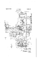
- Fig. l is a side elevation, partly in section, showing the complete machine.
- Fig. 2 is a horizontal section on the line 2-2, Fig. 1. i
- Fig. 3 is a vertical s ectionon the line 33, Fig. 1.
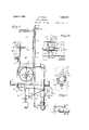
- Fig. 4 is an enlarged section on the line ea, Fig. 1.
- Figs. 5, 6 and 7 are enlarged end, side, and plaon views respectively of the propeller blade
- Fig. 8 is an enlarged detail section showing the assembly of the propeller hub.
- Fig. 9 is an enlarged section on the line 99, Fig. 1.
- Fig. 10 is an enlarged section showing the retarding valve in open position.
- Fig. 11 is an end elevation showing themlxing chamber and parts.
- my novel mixing machine preferably consists of a percentage control chamber A into which the dry feed enters, a safety control chamber B receiving the discharge from the chamber A, said chamber B discharging into a propulsionchamber C which discharges into an incorporating chamber D, the latter'discharging into a mixing chamber E in which the dry and liquid feeds are thoroughly mixed, the liquid feed having entered the machine at a point between the safety control chamber B and propulsion chamber G by means of the pipe line 1 which extends across the lower end of the chamber B and is provided with a series of holes 2 (Figs. 2 and 3) through which the liquid feed flows so as to come in contact with the dry feed as it descends into the propulsion chamber C.
- the assembled machine is carried in a suitable frame 3, the separate parts being mounted on the cross plates 4.
- the percentage control chamber A is preferably'of rectangular cross-section, open at the top, and is provided with a gate 5 pivoted horizontally on a shaft 6 disposed within and adjacent the upper end of chamber A, said gate 5 being adapted tobe adjusted (ashereinafter described) to regulate the amount of dry feed passing down through chamber A into chamber B, disposed directly below same.
- a similar gate 7 hereinafter referred to
- the dry feed drops from the percentage control chamber A, by gravity past the gates 5 and 7 into the safety chamber B, past the perforated liquid feed pipe 1, and into propulsion chamber C disposed below the safety control chamber.
- the propulsion chamber C incorporating chamber D, and mixing chamber E are preferably disposed in horizontal alignment and a shaft 8 extends axially through the chambers C, D and E, the same being journaled in suitable bearings 9 and driven by an electric motor or other prime mover through flexible coupling 11, or by any other suitable means.
- a chain sprocket 12 may be mounted on the shaft of motor 10 for the purpose of driving directly a circulating pump (not shown) by which the liquid feed is pumped through pipe 1 into the machine.
- a propeller unit consisting of a split hub 18 clamped to shaft 8 so as to rotate with shaft 8, said hub being provided with studs 14 and slots 15 (see Figs. 4, 5, 6 and 7).
- the propeller blades 16 Upon the studs 14 are rotatably mounted the propeller blades 16 by means of the nuts 1'? in such a manner that the blades are free to rotate around the studs 14 at anv desired angle.
- the rotation of the blades 16 is effected by pins 18 secured to the sides of the blades 16 which pins pass through the slots 15 in the hubs 18 and enter an annular recess 19 in a telescoping shifter sleeve 20 which is mounted axially of shaft 8 and is carried in the hearing 21 in the rear end of propulsion chamber 0.
- Bearing 21 is provided at the outer end with two angular slots 22 in which pins 28, secured on the sleeve 20 operate so that when the sleeve 20 is rotated by shifting the lever 24 (see Fig.
- the sleeve 20 will move lengthwise in bearing 21 and by so doing will move the pins 18 of the blades 16 causing the latter to turn on the studs 14 thereby changing the angularity of the blades to any desired degree.
- the movement of lever 24 is controlled by the clamp screw 25 which clamps it to the quadrant 26 in any desired position by means of the strap 27 which is a part of the lever.
- agitators 80 On the shaft 8 within the incorporating chamber D are secured a plurality of spaced agitators 80 each consisting of a hub having suitable arms adapted to agitate the feed material and incorporate the dry particles with the liquids and assist in passing the feed along to and through the retarding valve 81 into the mixing chamber E.
- This retarding valve 81' consists of a circular plate split radially to the center, said plate being secured on the side diametrically opposite the split to the chamber wall by pivot screw 82, (see Fig. 9).
- pivot screw 82 At each side of the split in this valve are secured bolts 88 and 84 respectively which pass out of the side of chamber D through suitable slots 8586, and connect with the vertical link 87 which rotates on the pivot 88 secured to the outside of the chamber wall.
- the vertical link 87 is connected at the upper end, by the horizontal link 89, to the lever 40 which is pivoted at its lower end 40a to the main frame of the machine.
- the position of lever 40 is regulated by the screw 42, clamping the quadrant 48 through the strap 44 which is part of the lever 40, (see Fig. 9).
- the above arrangement permits the portions of the plate adjacent the split being spread apart to form a spiral opening, as shown in Fig. 10, through which the feed passes from the incorporating chamber D into the mixing chamber E, the quantity depending on the degree
- the mixing chamber E In the mixing chamber E is a vertically disposed disk 45 secured to shaft 8 so as to rotate therewith.
- This disk carries the pins 46 which project horizontally into the cham ber as shown in Figs. 1, 2 and 11, their position in the disk 45 being shown in end elevation, Fig. 11.
- a row of stationary pins 4'? is placed in the wall of mixing chamber E opposite to the disk 45, which pins 47 project into the chamber, these being for the purpose of breaking up the feed as it is whirled around in the chamber by the rotating pins 46.
- the feed passes out of the chamber through the lower opening 48 into a suitable bag or receptacle R which may be attached thereto, and may be bagged or disposed of as desired.
- the chamber is also provided with an upper opening 49 which is closed by a cover plate 50 which is removable for the purpose of inspection.
- the feed control mechanism for the dry and liquid feeds is shown in Figs. 1 and 8 and consists of the gate 5 in the percentage control chamber A pivoted on the shaft 6, to the outer end of which shaft is secured the lever 58, said gate 5 being for the purpose of enlarging or diminishing the area of the opening through the percentage control chamber A. through which the dry feed material must pass.
- the lever 58 may be set at any desired angle on the quadrant 54 by the clamp screw 55.
- the quadrant 54 is provided with graduations 57 so that the gate may be set as desired to allow only the proper amount of dry food to pass down into and through the safety control chamber B and into the propulsion chamber C.
- lever 58 The inner end of lever 58 is provided with a slot 58 and graduations 59, and at this point is secured the upper end of a vertical rod 60 the upper end of which can be placed at any position in the slot 58 thereby obtaining a longer or shorter movementof the rod when lever 58 is adjusted to different points on the quadrant 54.
- the rod 60 is made in two parts and is provided with a turnbuckle 61 so that its length may be adjusted as desired.
- the lower end of rod is connected to the lever 62 on the control valve 63 in pipe 1 whereby the valve 63 will be opened or closed in proportion as lever 53 is raised or lowered, and as control gate 5 is opened or closed.
- the gate 7 carried on the shaft 65, to the outer end of which is secured the lever 66 on which is placed the slidable weight 67 so as to properly balance the gate 7 and allow same to swing freely at all times.
- an'electric contact point 68 which, as lever 66 rises or lowers in operating the gate, contacts with the adjustable contactbar 69 which has an electric terminal 70 at the upper end, contacts 68 and 70 being connected by wires 7172 to the solenoids 7874.
- a short section of adjustable contact bar 75 is so placed in relation to the bar 69 as to leave a gap between them, this bar has an electric terminal 76 at the lower end and is connected to the solenoids by the wire 77, the wires 717277 passing down through the conduit 78 secured to the bottom of the contact box 79 which is fastened to the percentage control chamber A and provided with a cover 80.
- Wires 8182 connect the control panel .83 (Fig. 3) and carry the electric current to the terminals 707 6. From control panel 83 the wires 8485 are carried to the solenoids 7 3-7 4 completing the electric circuit.
- the liquid pipe line 1 is provided with a meter 86 by which the liquid is accurately measured as it passes from the pump not shown) to the machine. Placed at the proper point in the line is the control valve 63 and in the vertical section of the line is located the electrically controlled valve 87 which is operated by the solenoids 7 74-. these being connected to the valve lever 88 by the links 89-90.
- the percentage control gate 5 is opened the desired amount, safety control gate 7 is closed the lever 66 being at its lower position in which electric contact point 68 is below and off the Contact bar 75, and the safety control valve 87 being closed so that no liquid can enter the machine although valve 63 is opened in pr0portion to the position of lever 53.
- safety control gate 7 When the dry feed material enters the percentage control chamber A it continues downwardly striking safety control gate 7 which is thus swung downwardly over against the wall of chamber B causing lever 66 to rise, the contact point 68 passing over the lower contact bar 7 5 jumps the gap and contacts with the upper contact bar 69 thereby operating the proper solenoid-and opening the safety control valve 87 so that the liquid can flow through pipe 1 into the machine, the quantity being controlled by the valve63.
- the safety control gate 7 When, the safety control gate 7 is in a vertical position the lever 66 is at its highest point of travel and as the contact point 68 has passed off the upper contact bar 69 noelectric current is consumed while the machine is in operation. When the flow of dry feed material is stopped for any reason the safety control gate 7 swings upwardly to closed position by means of the, weight 67, lever 66 swinging downwardly and contact point 68 passing overupper contact bar 69 jumps the gap, contacts the lower contact bar 75 closing the electric circuit and operating the proper solenoid to close the safety control valve 87 thereby making it impossible for any liquid to enter the machine.
- the feed material drops into the propulsion chamber 3 where it is moved forward by the propeller blades 16 continuing through the incorporating chamber D, where it is acted upon by the agitators 30 and further mixed with the liquid.
- the mixture then passes through the retarding valve 31 into the mixing chamber E where it is thoroughly mixed with the liquid and passes out through the lower opening 48 to be disposed of as desired.
- the rate of propulsion through chambers C, D, and E is governed by the setting of lever 24 which regulates the pitch of the propeller blades 16; also by the setting of lever 40 which controls the opening through the retarding valve 31.
- a machine for mixing dry and liquid materials comprising a horizontally disposed incorporating casing having an inlet chamber for the dry material; an inlet pipe in the chamber for the liquid material; a mixing chamber receiving the contents of the casing and having an outlet; a driven shaft extending through the casing and mixing chamber; means on the shaft for propelling the materials through the casing towards the mixing chamber; means for varying the rate of propulsion of said materials; means for retarding the passage of the materials into the mixing chamber; and means in the mixing chamber for intimately mixing the materials.
- said propellingmeans comprising a propeller mounted on said shaft; and said propulsion varying means comprising a hub on said shaft carrying the blades, said blades being rotatably mounted on said hub; an axially movable sleeve on said shaft adjacent said hub, said sleeve having an annular groove; pins on the propeller blades engaging the groove; and means for shifting the sleeve whereby the pitch of the propeller blades will be varied.
- said retarding means comprising a transverselydisposed plate adjacent the mixing chamber having a split in one side extending to the center; and means for forcing the portions of the plate at opposite sides of the split in opposite directions whereby a substantially spiral opening through the plate will be formed.
- said retarding means comprising a transversely disposed plate in the casing having a split in one side extending to the center of the plate; means at the side opposite the split for securing the plate to the casing; bolts secured to the plate at opposite sides of the split; an arm pivoted to the casing opposite the split and having offset bores receiving the ends of the bolts; and means for swinging the arm whereby the portions of the plate adjacent the split will be forced in opposite directions to form a substantially spiral opening through the plate.
- a horizontally disposed chamber adapted to receive material to be treated; a shaft extending axially through the chamber; means for rotating the shaft; a propeller on the shaft for propelling the material through the cas ing; and means for varying the rate of propulsion of the material irrespective of the rate of rotation of the shaft, comprising a hub on said shaft carrying the propeller blades, said blades being rotatably mounted on said hub; an axially movable sleeve on said shaft adjacent said hub, said sleeve having an annular groove; pins on the lower ends of the blades engaging the groove; and a lever for shifting the sleeve whereby the pitch of the propeller blades will be varied.
- a horizontally disposed chamber adapted to receive material to be treated; means for propelling the material through the chamber; a retarding plate in the end of the chamber having a split in one side extending to its approximate center; and means for forcing the portions of the plate at opposite sides of the split in opposite directions, whereby a substantially spiral opening will be formed through the plate.
- said means comprising bolts secured to the plate at opposite sides of the split; an arm pivoted to the casing opposite the split and having offset holes receiving the ends of the bolts; and a lever for swinging the arm whereby the portions of the plate adjacent the split will be forced apart.
- a casing having a vertically disposed inlet chamber for introducing the dry material; an inlet pipe for the liquid material discharging into the inlet chamber; a valve in said pipe; a gate in the chamber adapted to control the inlet opening; a lever for adjusting the gate; a link connecting the lever and valve; and means for varying the connection of the link with respect to the lever.
- said varying means comprising an axial slot in the lever; and graduations adjacent the slot; the end of the link being adjustable in the slot.
- a second gate in the inlet chamber with which the dry material contacts; a second valve in the liquid pipe; and connections between the second gate and second valve for automatically closing the valve when the contact ceases, and automatically opening the valve when the contact is resumed.
- a casing having a vertically disposed inlet chamber for introducing the dry material; an inlet pipe for the liquid material discharging into the inlet chamber; a valve in said pipe; a horizontally pivoted gate in the inlet chamber upon which the dry material falls; a counterbalancing arm for said gate normally maintaining the gate in raised position across the inlet chamber; a pair of oppositely acting solenoids for opening and closing the said valve; and electrical connections operated by the arm for exciting the respective solenoids whereby the valve will be automatically closed when the gate is in raised position and whereby the valve will be automatically opened when the gate is swung downwardly by the flow of material.
- said electrical connections comprising normally open electrical circuits including a contact carried by the arm, and contact bars disposed in the path of swing of said arm, and including the opposed solenoids; the circuits being closed while the contact engages the contact bars, and the contact being disengaged from the bars when the arm is in uppermost or lowermost positions.
Description
pril 5, 1932.
J. F. FIELD MIXING MACHINE Filed Nox}. 2
, 1950 4 Shets-Sheet k m/ I'IIIIIIIIIIIIIIIIIIIIII n/unnn I April 5, 1932.
J. F. FIELD MIXING MACHINE Filed Nov. 28, 1930 4 Sheets-Sheet 2 Y. O f. n e D n 3 April 5, 1932. F D 1,852,712
MIXING MACHINE Filed Nov. 28, 1930 4 Sheets-Sheet 3 Inwcntor i W Gt orncg:
April 5, 1932. J. F. FIELD MIXING MACHINE 4 Sheets-Sheet 4 Filed Nov. 28, 1930 Patented Apr. 5, 1932 nmrso STATES JOHN F. FIELD, OF OWOSSO, MICHIGAN MIXING MACHINE Application filed November 28, 1930. Serial No. 498,856.
This invention is a novel improvement in dry and. liquid feed mixing machines and the principal object of the invention is to provide a novel and efficient machine for mixing any liquid ingredient with dry or semi-dried feeds or any kind. for any purpose and in any determined proportions.
Another object of the invention is to provide a machine of the above type having novel means for propelling the mixed feed through the incorporating chamber consisting of a shaft having propeller blades with means for readily varying the pitch of the propeller blades with relation to the shaft to vary the feed.
Another object of the invention is to pro vide a machine of the above type having a novel retarding valve for varying the propulsion of dry and liquid feed from the incorporating chamber into the mixing chamber. 1
Another object is to provide a novel mixing chamber for thoroughly mixing the dry and liquid feeds.
Another object of the invention is to provide a machine of the above type with novel control means whereby the flow of liquid into the machine will be automatically checked any time that the flow of dry feed ceases, and whereby the liquid feed will again proceed to flow as soon as the flow of dry feed commences.
Other minor objects of the invention will be hereinafter set forth.
I will explain the invention with reference to the accompanying drawings which illustrate one practical embodiment thereof to enable others familiar with the art to adopt and use the same; and will summarize in the claims the novel features of construction, and novel combinations of parts, for which protection is desired.
In said drawings;
Fig. l is a side elevation, partly in section, showing the complete machine.
Fig. 2 is a horizontal section on the line 2-2, Fig. 1. i
Fig. 3 is a vertical s ectionon the line 33, Fig. 1.
Fig. 4 is an enlarged section on the line ea, Fig. 1.
Figs. 5, 6 and 7 are enlarged end, side, and plaon views respectively of the propeller blade Fig. 8 is an enlarged detail section showing the assembly of the propeller hub.
Fig. 9 is an enlarged section on the line 99, Fig. 1.
Fig. 10 is an enlarged section showing the retarding valve in open position.
Fig. 11 is an end elevation showing themlxing chamber and parts.
As shown in the drawings, my novel mixing machine preferably consists of a percentage control chamber A into which the dry feed enters, a safety control chamber B receiving the discharge from the chamber A, said chamber B discharging into a propulsionchamber C which discharges into an incorporating chamber D, the latter'discharging into a mixing chamber E in which the dry and liquid feeds are thoroughly mixed, the liquid feed having entered the machine at a point between the safety control chamber B and propulsion chamber G by means of the pipe line 1 which extends across the lower end of the chamber B and is provided with a series of holes 2 (Figs. 2 and 3) through which the liquid feed flows so as to come in contact with the dry feed as it descends into the propulsion chamber C. The assembled machine is carried in a suitable frame 3, the separate parts being mounted on the cross plates 4.
The percentage control chamber A is preferably'of rectangular cross-section, open at the top, and is provided with a gate 5 pivoted horizontally on a shaft 6 disposed within and adjacent the upper end of chamber A, said gate 5 being adapted tobe adjusted (ashereinafter described) to regulate the amount of dry feed passing down through chamber A into chamber B, disposed directly below same. In chamber B is a similar gate 7 (hereinafter referred to) and the dry feed drops from the percentage control chamber A, by gravity past the gates 5 and 7 into the safety chamber B, past the perforated liquid feed pipe 1, and into propulsion chamber C disposed below the safety control chamber.
The propulsion chamber C incorporating chamber D, and mixing chamber E are preferably disposed in horizontal alignment and a shaft 8 extends axially through the chambers C, D and E, the same being journaled in suitable bearings 9 and driven by an electric motor or other prime mover through flexible coupling 11, or by any other suitable means. A chain sprocket 12 may be mounted on the shaft of motor 10 for the purpose of driving directly a circulating pump (not shown) by which the liquid feed is pumped through pipe 1 into the machine.
On shaft 8 within the propulsion chamber C is a propeller unit consisting of a split hub 18 clamped to shaft 8 so as to rotate with shaft 8, said hub being provided with studs 14 and slots 15 (see Figs. 4, 5, 6 and 7). Upon the studs 14 are rotatably mounted the propeller blades 16 by means of the nuts 1'? in such a manner that the blades are free to rotate around the studs 14 at anv desired angle. The rotation of the blades 16 is effected by pins 18 secured to the sides of the blades 16 which pins pass through the slots 15 in the hubs 18 and enter an annular recess 19 in a telescoping shifter sleeve 20 which is mounted axially of shaft 8 and is carried in the hearing 21 in the rear end of propulsion chamber 0. Bearing 21 is provided at the outer end with two angular slots 22 in which pins 28, secured on the sleeve 20 operate so that when the sleeve 20 is rotated by shifting the lever 24 (see Fig. 8) the sleeve 20 will move lengthwise in bearing 21 and by so doing will move the pins 18 of the blades 16 causing the latter to turn on the studs 14 thereby changing the angularity of the blades to any desired degree. The movement of lever 24 is controlled by the clamp screw 25 which clamps it to the quadrant 26 in any desired position by means of the strap 27 which is a part of the lever.
On the shaft 8 within the incorporating chamber D are secured a plurality of spaced agitators 80 each consisting of a hub having suitable arms adapted to agitate the feed material and incorporate the dry particles with the liquids and assist in passing the feed along to and through the retarding valve 81 into the mixing chamber E.
This retarding valve 81'consists of a circular plate split radially to the center, said plate being secured on the side diametrically opposite the split to the chamber wall by pivot screw 82, (see Fig. 9). At each side of the split in this valve are secured bolts 88 and 84 respectively which pass out of the side of chamber D through suitable slots 8586, and connect with the vertical link 87 which rotates on the pivot 88 secured to the outside of the chamber wall. The vertical link 87 is connected at the upper end, by the horizontal link 89, to the lever 40 which is pivoted at its lower end 40a to the main frame of the machine. The position of lever 40 is regulated by the screw 42, clamping the quadrant 48 through the strap 44 which is part of the lever 40, (see Fig. 9). The above arrangement permits the portions of the plate adjacent the split being spread apart to form a spiral opening, as shown in Fig. 10, through which the feed passes from the incorporating chamber D into the mixing chamber E, the quantity depending on the degree of opening of the valve 81.
In the mixing chamber E is a vertically disposed disk 45 secured to shaft 8 so as to rotate therewith. This disk carries the pins 46 which project horizontally into the cham ber as shown in Figs. 1, 2 and 11, their position in the disk 45 being shown in end elevation, Fig. 11. A row of stationary pins 4'? is placed in the wall of mixing chamber E opposite to the disk 45, which pins 47 project into the chamber, these being for the purpose of breaking up the feed as it is whirled around in the chamber by the rotating pins 46. The feed passes out of the chamber through the lower opening 48 into a suitable bag or receptacle R which may be attached thereto, and may be bagged or disposed of as desired. The chamber is also provided with an upper opening 49 which is closed by a cover plate 50 which is removable for the purpose of inspection.
The feed control mechanism for the dry and liquid feeds is shown in Figs. 1 and 8 and consists of the gate 5 in the percentage control chamber A pivoted on the shaft 6, to the outer end of which shaft is secured the lever 58, said gate 5 being for the purpose of enlarging or diminishing the area of the opening through the percentage control chamber A. through which the dry feed material must pass. The lever 58 may be set at any desired angle on the quadrant 54 by the clamp screw 55. The quadrant 54 is provided with graduations 57 so that the gate may be set as desired to allow only the proper amount of dry food to pass down into and through the safety control chamber B and into the propulsion chamber C. The inner end of lever 58 is provided with a slot 58 and graduations 59, and at this point is secured the upper end of a vertical rod 60 the upper end of which can be placed at any position in the slot 58 thereby obtaining a longer or shorter movementof the rod when lever 58 is adjusted to different points on the quadrant 54. The rod 60 is made in two parts and is provided with a turnbuckle 61 so that its length may be adjusted as desired. The lower end of rod is connected to the lever 62 on the control valve 63 in pipe 1 whereby the valve 63 will be opened or closed in proportion as lever 53 is raised or lowered, and as control gate 5 is opened or closed.
Directly below the gate 5 in percentage chamber A, within the safety control chamber B is the gate 7 carried on the shaft 65, to the outer end of which is secured the lever 66 on which is placed the slidable weight 67 so as to properly balance the gate 7 and allow same to swing freely at all times. In the outer end of lever 66 is located an'electric contact point 68 which, as lever 66 rises or lowers in operating the gate, contacts with the adjustable contactbar 69 which has an electric terminal 70 at the upper end, contacts 68 and 70 being connected by wires 7172 to the solenoids 7874. A short section of adjustable contact bar 75 is so placed in relation to the bar 69 as to leave a gap between them, this bar has an electric terminal 76 at the lower end and is connected to the solenoids by the wire 77, the wires 717277 passing down through the conduit 78 secured to the bottom of the contact box 79 which is fastened to the percentage control chamber A and provided with a cover 80. Wires 8182 connect the control panel .83 (Fig. 3) and carry the electric current to the terminals 707 6. From control panel 83 the wires 8485 are carried to the solenoids 7 3-7 4 completing the electric circuit.
The liquid pipe line 1 is provided with a meter 86 by which the liquid is accurately measured as it passes from the pump not shown) to the machine. Placed at the proper point in the line is the control valve 63 and in the vertical section of the line is located the electrically controlled valve 87 which is operated by the solenoids 7 74-. these being connected to the valve lever 88 by the links 89-90.
In operation of the machine, the percentage control gate 5 is opened the desired amount, safety control gate 7 is closed the lever 66 being at its lower position in which electric contact point 68 is below and off the Contact bar 75, and the safety control valve 87 being closed so that no liquid can enter the machine although valve 63 is opened in pr0portion to the position of lever 53. When the dry feed material enters the percentage control chamber A it continues downwardly striking safety control gate 7 which is thus swung downwardly over against the wall of chamber B causing lever 66 to rise, the contact point 68 passing over the lower contact bar 7 5 jumps the gap and contacts with the upper contact bar 69 thereby operating the proper solenoid-and opening the safety control valve 87 so that the liquid can flow through pipe 1 into the machine, the quantity being controlled by the valve63. When, the safety control gate 7 is in a vertical position the lever 66 is at its highest point of travel and as the contact point 68 has passed off the upper contact bar 69 noelectric current is consumed while the machine is in operation. When the flow of dry feed material is stopped for any reason the safety control gate 7 swings upwardly to closed position by means of the, weight 67, lever 66 swinging downwardly and contact point 68 passing overupper contact bar 69 jumps the gap, contacts the lower contact bar 75 closing the electric circuit and operating the proper solenoid to close the safety control valve 87 thereby making it impossible for any liquid to enter the machine.
After passing through the percentage chamber A and the safety control chamber B and being impregnated with the liquid flowing in through the pipe line 1, the feed material drops into the propulsion chamber 3 where it is moved forward by the propeller blades 16 continuing through the incorporating chamber D, where it is acted upon by the agitators 30 and further mixed with the liquid. The mixture then passes through the retarding valve 31 into the mixing chamber E where it is thoroughly mixed with the liquid and passes out through the lower opening 48 to be disposed of as desired. The rate of propulsion through chambers C, D, and E is governed by the setting of lever 24 which regulates the pitch of the propeller blades 16; also by the setting of lever 40 which controls the opening through the retarding valve 31.
I do not limit my invention to the exact formshown in the drawings for obviously changes may be made therein within the scope of the claims.
I claim 1. A machine for mixing dry and liquid materials, comprising a horizontally disposed incorporating casing having an inlet chamber for the dry material; an inlet pipe in the chamber for the liquid material; a mixing chamber receiving the contents of the casing and having an outlet; a driven shaft extending through the casing and mixing chamber; means on the shaft for propelling the materials through the casing towards the mixing chamber; means for varying the rate of propulsion of said materials; means for retarding the passage of the materials into the mixing chamber; and means in the mixing chamber for intimately mixing the materials.
2. In combination with a machine as set forth in the claim 1, means for automatically proportioning the amounts of dry and liquid materials entering the machine.
3. In combination with a machine as set forth in claim 1, means for automatically proportioning the amounts of dry and liquid materials entering the machine; and means for automatically checking the flow of liquid material into the machine by and with the flow of dry material,
4. In. a machine as set forth in claim 1, said propellingmeans comprising a propeller mounted on said shaft; and said propulsion varying means comprising a hub on said shaft carrying the blades, said blades being rotatably mounted on said hub; an axially movable sleeve on said shaft adjacent said hub, said sleeve having an annular groove; pins on the propeller blades engaging the groove; and means for shifting the sleeve whereby the pitch of the propeller blades will be varied.
5. In a machine as set forth in claim 1, said retarding means comprising a transverselydisposed plate adjacent the mixing chamber having a split in one side extending to the center; and means for forcing the portions of the plate at opposite sides of the split in opposite directions whereby a substantially spiral opening through the plate will be formed.
6. In a machine as set forth in claim 1, said retarding means comprising a transversely disposed plate in the casing having a split in one side extending to the center of the plate; means at the side opposite the split for securing the plate to the casing; bolts secured to the plate at opposite sides of the split; an arm pivoted to the casing opposite the split and having offset bores receiving the ends of the bolts; and means for swinging the arm whereby the portions of the plate adjacent the split will be forced in opposite directions to form a substantially spiral opening through the plate.
7 In a machine of the character specified, a horizontally disposed chamber adapted to receive material to be treated; a shaft extending axially through the chamber; means for rotating the shaft; a propeller on the shaft for propelling the material through the cas ing; and means for varying the rate of propulsion of the material irrespective of the rate of rotation of the shaft, comprising a hub on said shaft carrying the propeller blades, said blades being rotatably mounted on said hub; an axially movable sleeve on said shaft adjacent said hub, said sleeve having an annular groove; pins on the lower ends of the blades engaging the groove; and a lever for shifting the sleeve whereby the pitch of the propeller blades will be varied.
8. In a machine of the character specified, a horizontally disposed chamber adapted to receive material to be treated; means for propelling the material through the chamber; a retarding plate in the end of the chamber having a split in one side extending to its approximate center; and means for forcing the portions of the plate at opposite sides of the split in opposite directions, whereby a substantially spiral opening will be formed through the plate.
9. In a machine as set forth in claim 8, said means comprising bolts secured to the plate at opposite sides of the split; an arm pivoted to the casing opposite the split and having offset holes receiving the ends of the bolts; and a lever for swinging the arm whereby the portions of the plate adjacent the split will be forced apart.
10. In a machine for mixing dry and liquid materials; a casing having a vertically disposed inlet chamber for introducing the dry material; an inlet pipe for the liquid material discharging into the inlet chamber; a valve in said pipe; a gate in the chamber adapted to control the inlet opening; a lever for adjusting the gate; a link connecting the lever and valve; and means for varying the connection of the link with respect to the lever.
11. In a machine as set forth in claim 10, said varying means comprising an axial slot in the lever; and graduations adjacent the slot; the end of the link being adjustable in the slot.
12. In combination with a machine as set forth in claim 10; a second gate in the inlet chamber with which the dry material contacts; a second valve in the liquid pipe; and connections between the second gate and second valve for automatically closing the valve when the contact ceases, and automatically opening the valve when the contact is resumed.
13. In a machine for mixing dry and liquid materials, a casing having a vertically disposed inlet chamber for introducing the dry material; an inlet pipe for the liquid material discharging into the inlet chamber; a valve in said pipe; a horizontally pivoted gate in the inlet chamber upon which the dry material falls; a counterbalancing arm for said gate normally maintaining the gate in raised position across the inlet chamber; a pair of oppositely acting solenoids for opening and closing the said valve; and electrical connections operated by the arm for exciting the respective solenoids whereby the valve will be automatically closed when the gate is in raised position and whereby the valve will be automatically opened when the gate is swung downwardly by the flow of material.
14. In a machine as set forth in claim 13, said electrical connections comprising normally open electrical circuits including a contact carried by the arm, and contact bars disposed in the path of swing of said arm, and including the opposed solenoids; the circuits being closed while the contact engages the contact bars, and the contact being disengaged from the bars when the arm is in uppermost or lowermost positions.
15. In combination with a machine as set forth in claim 13, a second gate in the inlet
Priority Applications (1)
| Application Number | Priority Date | Filing Date | Title |
|---|---|---|---|
| US498856A US1852712A (en) | 1930-11-28 | 1930-11-28 | Mixing machine |
Applications Claiming Priority (1)
| Application Number | Priority Date | Filing Date | Title |
|---|---|---|---|
| US498856A US1852712A (en) | 1930-11-28 | 1930-11-28 | Mixing machine |
Publications (1)
| Publication Number | Publication Date |
|---|---|
| US1852712A true US1852712A (en) | 1932-04-05 |
Family
ID=23982787
Family Applications (1)
| Application Number | Title | Priority Date | Filing Date |
|---|---|---|---|
| US498856A Expired - Lifetime US1852712A (en) | 1930-11-28 | 1930-11-28 | Mixing machine |
Country Status (1)
| Country | Link |
|---|---|
| US (1) | US1852712A (en) |
Cited By (3)
| Publication number | Priority date | Publication date | Assignee | Title |
|---|---|---|---|---|
| US2487533A (en) * | 1946-02-25 | 1949-11-08 | Roland Turck | Mixer for dry and wet ingredients |
| US2522936A (en) * | 1948-05-17 | 1950-09-19 | James E Ferguson | Apparatus for fluffing asbestos |
| US2825511A (en) * | 1953-05-26 | 1958-03-04 | Jonas J Byberg | Feed mixer and grinder |
-
1930
- 1930-11-28 US US498856A patent/US1852712A/en not_active Expired - Lifetime
Cited By (3)
| Publication number | Priority date | Publication date | Assignee | Title |
|---|---|---|---|---|
| US2487533A (en) * | 1946-02-25 | 1949-11-08 | Roland Turck | Mixer for dry and wet ingredients |
| US2522936A (en) * | 1948-05-17 | 1950-09-19 | James E Ferguson | Apparatus for fluffing asbestos |
| US2825511A (en) * | 1953-05-26 | 1958-03-04 | Jonas J Byberg | Feed mixer and grinder |
Similar Documents
| Publication | Publication Date | Title |
|---|---|---|
| US1226108A (en) | Measuring and mixing device. | |
| US1852712A (en) | Mixing machine | |
| US2174089A (en) | Mixing apparatus | |
| US3140861A (en) | Mixing device | |
| US4576483A (en) | Apparatus for mixing and metering flowable solid materials | |
| US3362689A (en) | Immersion mixing apparatus | |
| US2164257A (en) | Sweet-feed mixer | |
| US2487533A (en) | Mixer for dry and wet ingredients | |
| US1884423A (en) | Mixer | |
| US3305222A (en) | Apparatus for preparing batches of concrete | |
| US2301461A (en) | Yeast emulsifier | |
| US2547403A (en) | Material mixing apparatus | |
| US3092882A (en) | Apparatus for measuring and controlling moisture content of materials | |
| US2324580A (en) | Liquid metering and mixing apparatus | |
| US3331357A (en) | Apparatus for the mixing and feeding of liquid food to suckling animals | |
| US1713568A (en) | Force-feed seed-treating machine | |
| US3182968A (en) | Belt type feed blender | |
| US1760906A (en) | Mixing machine for viscous and granular materials | |
| US3037671A (en) | Feed mixing device | |
| US2600333A (en) | Molasses mixer | |
| US682528A (en) | Ore-sampling machine. | |
| US1233198A (en) | Apparatus for mixing concrete. | |
| US851686A (en) | Concrete-mixer. | |
| US3414173A (en) | Materials conditioning, weigh blender system | |
| US1137294A (en) | Apparatus for mixing slurry. |