US1852674A - Stocking inspecting device - Google Patents
Stocking inspecting device Download PDFInfo
- Publication number
- US1852674A US1852674A US473432A US47343230A US1852674A US 1852674 A US1852674 A US 1852674A US 473432 A US473432 A US 473432A US 47343230 A US47343230 A US 47343230A US 1852674 A US1852674 A US 1852674A
- Authority
- US
- United States
- Prior art keywords
- stocking
- blank
- arms
- inspecting
- leg
- Prior art date
- Legal status (The legal status is an assumption and is not a legal conclusion. Google has not performed a legal analysis and makes no representation as to the accuracy of the status listed.)
- Expired - Lifetime
Links
Images

Classifications
-
- D—TEXTILES; PAPER
- D06—TREATMENT OF TEXTILES OR THE LIKE; LAUNDERING; FLEXIBLE MATERIALS NOT OTHERWISE PROVIDED FOR
- D06H—MARKING, INSPECTING, SEAMING OR SEVERING TEXTILE MATERIALS
- D06H3/00—Inspecting textile materials
- D06H3/16—Inspecting hosiery or other tubular fabric; Inspecting in combination with turning inside-out, classifying, or other handling
Definitions
- This invention relates to inspecting devices and more particularly to a device by the use of which leg blanks of full fashioned stockings may be examined in order to discover defects. 7
- one object of this invention is to provide a device by means of which not only the body portion of the leg but also the heel tabs may be held flat and thereby easily and quickly inspected.
- Another object of the invention is to so form the inspecting device that it may be set upon aleg blank and moved longitudinally along the same, thereby progressively flattening the blank for its full width and per mitting all portions of the blank to be inspected.
- Another object of the invention is to provide a device of this character which is very simple in construction and easy to operate.
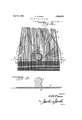
- Figure 1 is a view showing the device in use.
- Figure 2 is a view showing the inspecting device shifted to another position upon a stocking
- Figure 3 is a sectional view taken along the line 3-3 of Figure 2.
- This improved inspecting device is referred to as a device for inspecting leg blanks of full fashioned stockings but it is to be understood that it could be used for inspecting any fabric article. It will be also understood that the outline and dimensions of the device may be varied as found necessary.
- This device which is indicated in general by the numeral 1 is formed of transparent material such as glass and is in the form of a sheet having sufficient thickness to impart the necessary weight.
- This sheet is of greater width than the stocking or other article to be inspected and intermediate its width carries a handle 2 by means of which it may be easily set in place and moved along the stocking.
- the lower portion of the sheet may be side edges of arms 3 which extend longitudinally of the sheet and form the upper por tion thereof. These arms are spaced from each other transversely of the sheet and taper upwardly. It should be noted that the arms are so spaced and of such shape thatwhen he device is set in place upon a stocking as shown in full lines in Figure 1, the upper ends of the arms will be disposed midway the side edges thereof. Therefore, the device may be, 1noved along the stocking blank and the portion of the blank upon which it rests will be held flat and smooth so that the blank may be seen for its full width and defects easily detected.
- Figures 1 and 2 the device has been shown in various positions occupied during inspection of a leg blank and it will be understood that during inspection the device is set in place upon a stocking blank and slid along the stocking longitudially thereof.
- the device is shown in place near the top of the stocking leg and at one side thereof is shown a small narrowing hole 6 while at its other side is shown at 7 a defect in the welt.
- the position indicated by dotted lines in Figure 1 shows that the device has been shifted longitudinally of the stocking from the position of Figure 2 toward theposition shown in full lines in Figure 1.
- Defects in the selvage are indicated at 8 and 9 and at 10 and 11 are shown a bad selvage on the inside of one heel top 5 and hole in the outside selvage of the other heel top.
- the device consists of a thick sheet of plate glass and has tapered arms it can be set upon one end portion of a leg blank aft-er unroll ing this end of the blank and as the device is shifted along the blank, the blank will be spread by the arms and held fiat by the weight of the device.
- the arms serve to unroll and flatten the heel tops 5. Therefore,'all portions of the blank will be spread and held in a flattened condition during inspection and defects easily de- 1 tected. I have therefore provided a devlce which increases ease and speed of inspection and have further provided a device for this purpose Which is very simple in construction and easy to operate.
- An inspecting device for a leg blank of a stocking comprising. atsheet citransparent material of a greater Width at one end than .therstocking blank 'and havingits other end .-,lior1necl ;witl1 longitudinally extending: arms ,hspaced transverselyifrom each other.
- a leg blank of haostocking comprising asheet of transparent ,material of greater Width at oneend than the stocking blank and 7 having its 7 other eend .formed with longitudinally extending arms tapered; towards their free. ends.
- a ninspecting device for a leg blank of eastocking comprising a sheet of transparent Y material ofi greater Width at one endthanthe stocking blank, thesheetbeing of appreciable .less depth thanthelength of a stocking blank and havin g its other end formed Withlongitudinally extending arms spaced-transverselyrfrom each other; and tapered towardstheir free ends and having their free ends spaced rfromeach other a sufficient distance: for the .arms to :engage heel-.tops-midway the side hedges-thereof.
Description
April 5, 1932.
o. H. FONS STOCKING INSPECTING DEVICE 2 Sheets-Sheet 1 gwuentox p I 0'HP0718 Filed Aug. 6, 1930 dual/M115 STOCKING INSPEGTING DEVICE Filed Aug. 6, 1930 2 Sheets-Sheet 2 gwuewtoc QHPons v al ke mug:
Patented Apr. 5, 1932 UNITED STATES ONERIME H. POINS, F VALDESE, NORTH CAROLINA STOCKING INSPECTING DEVICE Application filed August 6, 1930. Serial No. 473,432.
This invention relates to inspecting devices and more particularly to a device by the use of which leg blanks of full fashioned stockings may be examined in order to discover defects. 7
When a leg of a full fashioned stocking is removed from the legger it usually rolls transversely from one or both sides. This makes it difficult to inspect the legs in order to discover defects and therefore, one object of this invention is to provide a device by means of which not only the body portion of the leg but also the heel tabs may be held flat and thereby easily and quickly inspected.
Another object of the invention is to so form the inspecting device that it may be set upon aleg blank and moved longitudinally along the same, thereby progressively flattening the blank for its full width and per mitting all portions of the blank to be inspected.
Another object of the invention is to provide a device of this character which is very simple in construction and easy to operate.
The invention is illustrated in the accompanying drawings wherein:
Figure 1 is a view showing the device in use.
Figure 2 is a view showing the inspecting device shifted to another position upon a stocking, and
Figure 3 is a sectional view taken along the line 3-3 of Figure 2.
This improved inspecting device is referred to as a device for inspecting leg blanks of full fashioned stockings but it is to be understood that it could be used for inspecting any fabric article. It will be also understood that the outline and dimensions of the device may be varied as found necessary.
This device which is indicated in general by the numeral 1 is formed of transparent material such as glass and is in the form of a sheet having sufficient thickness to impart the necessary weight. This sheet is of greater width than the stocking or other article to be inspected and intermediate its width carries a handle 2 by means of which it may be easily set in place and moved along the stocking. The lower portion of the sheet may be side edges of arms 3 which extend longitudinally of the sheet and form the upper por tion thereof. These arms are spaced from each other transversely of the sheet and taper upwardly. It should be noted that the arms are so spaced and of such shape thatwhen he device is set in place upon a stocking as shown in full lines in Figure 1, the upper ends of the arms will be disposed midway the side edges thereof. Therefore, the device may be, 1noved along the stocking blank and the portion of the blank upon which it rests will be held flat and smooth so that the blank may be seen for its full width and defects easily detected.
In Figures 1 and 2 the device has been shown in various positions occupied during inspection of a leg blank and it will be understood that during inspection the device is set in place upon a stocking blank and slid along the stocking longitudially thereof. In Figure 2 the device is shown in place near the top of the stocking leg and at one side thereof is shown a small narrowing hole 6 while at its other side is shown at 7 a defect in the welt. The position indicated by dotted lines in Figure 1 shows that the device has been shifted longitudinally of the stocking from the position of Figure 2 toward theposition shown in full lines in Figure 1. Defects in the selvage are indicated at 8 and 9 and at 10 and 11 are shown a bad selvage on the inside of one heel top 5 and hole in the outside selvage of the other heel top. Since the device consists of a thick sheet of plate glass and has tapered arms it can be set upon one end portion of a leg blank aft-er unroll ing this end of the blank and as the device is shifted along the blank, the blank will be spread by the arms and held fiat by the weight of the device. When the device is in the position shown in full lines in Figure 1 the arms serve to unroll and flatten the heel tops 5. Therefore,'all portions of the blank will be spread and held in a flattened condition during inspection and defects easily de- 1 tected. I have therefore provided a devlce which increases ease and speed of inspection and have further provided a device for this purpose Which is very simple in construction and easy to operate.
While I have shown the preferred embodiment of my invention, it is to be understood that various changes in the size,-shape .an'd arrangement 10f" parts may be" resorted 'to Without departing from the spirit of the invention and the scope of the appended claims.
Having described the invention What 1 claim is:
1. An inspecting device for a leg blank of a stocking comprising. atsheet citransparent material of a greater Width at one end than .therstocking blank 'and havingits other end .-,lior1necl ;witl1 longitudinally extending: arms ,hspaced transverselyifrom each other.
:2. .An inspecting device for. a leg blank of haostocking comprising asheet of transparent ,material of greater Width at oneend than the stocking blank and 7 having its 7 other eend .formed with longitudinally extending arms tapered; towards their free. ends.
v3.. A ninspecting device for a leg blank of eastocking comprising a sheet of transparent Y material ofi greater Width at one endthanthe stocking blank, thesheetbeing of appreciable .less depth thanthelength of a stocking blank and havin g its other end formed Withlongitudinally extending arms spaced-transverselyrfrom each other; and tapered towardstheir free ends and having their free ends spaced rfromeach other a sufficient distance: for the .arms to :engage heel-.tops-midway the side hedges-thereof.
.lnv testimony whereof Ivaiiix. my signature.
-ONERIME H. :PONS.
Priority Applications (1)
| Application Number | Priority Date | Filing Date | Title |
|---|---|---|---|
| US473432A US1852674A (en) | 1930-08-06 | 1930-08-06 | Stocking inspecting device |
Applications Claiming Priority (1)
| Application Number | Priority Date | Filing Date | Title |
|---|---|---|---|
| US473432A US1852674A (en) | 1930-08-06 | 1930-08-06 | Stocking inspecting device |
Publications (1)
| Publication Number | Publication Date |
|---|---|
| US1852674A true US1852674A (en) | 1932-04-05 |
Family
ID=23879497
Family Applications (1)
| Application Number | Title | Priority Date | Filing Date |
|---|---|---|---|
| US473432A Expired - Lifetime US1852674A (en) | 1930-08-06 | 1930-08-06 | Stocking inspecting device |
Country Status (1)
| Country | Link |
|---|---|
| US (1) | US1852674A (en) |
Cited By (1)
| Publication number | Priority date | Publication date | Assignee | Title |
|---|---|---|---|---|
| US5564169A (en) * | 1993-12-03 | 1996-10-15 | Milliken Research Corporation | Method and apparatus for optically simulating moire fabric |
-
1930
- 1930-08-06 US US473432A patent/US1852674A/en not_active Expired - Lifetime
Cited By (1)
| Publication number | Priority date | Publication date | Assignee | Title |
|---|---|---|---|---|
| US5564169A (en) * | 1993-12-03 | 1996-10-15 | Milliken Research Corporation | Method and apparatus for optically simulating moire fabric |
Similar Documents
| Publication | Publication Date | Title |
|---|---|---|
| US1852674A (en) | Stocking inspecting device | |
| US1748389A (en) | Mica sheet | |
| US2010172A (en) | Expansible form for inspecting hosiery | |
| USD87732S (en) | Design fob a sock | |
| AU396031A (en) | Improvements in knitted fabrics and articles andin machines forthe production thereof | |
| USD84283S (en) | Perceval s | |
| GB219263A (en) | Improvements in telescopic rods or stands for display purposes | |
| CA255480A (en) | Display device for textile goods and similar articles | |
| AT136614B (en) | Knitted or knitted goods, in particular stockings | |
| AU2086229A (en) | Improvements in seamless hosiery | |
| ES107850A1 (en) | Perfection in radio-receivers and other similar high-frequency receivers. | |
| FR703230A (en) | Improvements made to supports intended to allow ovoid-shaped bodies to be held in place, in particular for items such as egg cups or the like | |
| FR766055A (en) | Hosiery and the like | |
| GB334574A (en) | Improvements in or relating to parallel knitting-machines and to fabrics knitted thereon | |
| GB247758A (en) | Improvements in and connected with flat knitting machines | |
| ES135246A3 (en) | Improvements in the manufacturing process for stockings, socks and similar items. | |
| FR778784A (en) | Improvements in the manufacture of tube forming bags, or bags of paper or the like | |
| GB297542A (en) | Improvements in knitted fabrics and the method of making same | |
| AU2708430A (en) | Improvements in or relating to multiple ply textile fabrics | |
| AU451726A (en) | Improvements in fabrics with patterns printed thereon | |
| AU31831A (en) | Improvements in needle holding handles for repairing runs in knitted goods | |
| ES140516A3 (en) | Manufacturing process of covers or bedspreads, one piece, rugs, table runners, cushions, curtains or portiers, quilts and similar items, in any kind of measurements and drawings. | |
| AU1445333A (en) | Improvements in mechanism for use inthe shrinking and stretching of woven and like fabrics | |
| GB316591A (en) | Improvements in or relating to plated knitted fabric and to processes for making the same | |
| ES119037A1 (en) | Improvements in the manufacture of socks and stockings. |